Table of Contents
Advertisement
Congratulations on owning a Scag mower! This manual contains the
operating instructions and safety information for your Scag mower. Reading
this manual can provide you with assistance in maintenance and adjustment
procedures to keep your mower performing to maximum efficiency. The
specific models that this book covers are listed on the inside cover. Before
operating your machine, please read all the information enclosed.
© 2010
Scag Power Equipment
Division of Metalcraft of Mayville, Inc.
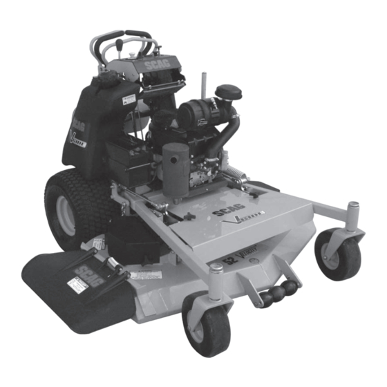
OPERATOR'S
MANUAL
V-Ride
Model:
SVR36A-20FX
SVR48V-24FX
SVR52V-26FX
Part No. 03259
Printed 1/10
Printed in USA
Advertisement
Table of Contents

Related Manuals for Scag Power Equipment V-RIDE SVR36A-20FX


Summary of Contents for Scag Power Equipment V-RIDE SVR36A-20FX
- Page 1 The specific models that this book covers are listed on the inside cover. Before operating your machine, please read all the information enclosed. © 2010 Scag Power Equipment Division of Metalcraft of Mayville, Inc. OPERATOR’S MANUAL...
- Page 2 FAILURE TO FOLLOW SAFE OPERATING PRACTICES MAY RESULT IN SERIOUS INJURY OR DEATH. • Read this manual completely as well as other manuals that came with your mower. • ALWAYS FOLLOW OSHA APPROVED OPERATION. • DO NOT operate on steep slopes. •...
-
Page 3: Table Of Contents
Table of Contents SECTION 1 - GENERAL INFORMATION 1.1 INTRODUCTION ...1 1.2 DIRECTION REFERENCE ...1 1.3 SERvICING THE ENGINE AND DRIvE TRAIN COMPONENTS ...1 1.4 SYMBOLS ...2 SECTION 2 - SAFETY INFORMATION 2.1 INTRODUCTION ...3 2.2 SIGNAL WORDS ...3 2.3 BEFORE OPERATION CONSIDERATIONS ...3 2.4 OPERATION CONSIDERATIONS ...4 2.5 MAINTENANCE CONSIDERATIONS &... - Page 4 SECTION 6 - ADJUSTMENTS 6.1 PARkING BRAkE ADJUSTMENT ...19 6.2 TRAvEL ADJUSTMENT ...19 6.3 THROTTLE CONTROL AND CHOkE ADJUSTMENTS ...21 6.4 BELT ADJUSTMENTS ...21 6.5 BELT ALIGNMENT ...21 6.6 CUTTER DECk ADJUSTMENTS ...21 6.7 ELECTRIC CLUTCH ADJUSTMENT ...26 6.8 FRONT WEIGHT ADJUSTMENT ...26 6.9 OPERATOR CUSHION ADJUSTMENT ...27 SECTION 7 - MAINTENANCE...
-
Page 5: General Information
All information is based upon product information available at the time of approval for printing. Scag Power Equipment reserves the right to make changes at any time without notice and without incurring any obligation. -
Page 6: Symbols
SYMBOLS SYMBOL DESCRIPTION Choke Parking Brake On/Start Off/Stop Falling Hazard Fast Continuously Variable - Linear Pinch Point 481039S Hour meter/Elapsed Operating Hours Crush Hazard. Thrown Object Hazard Keep Bystanders Away SYMBOL DESCRIPTION Transmission Spinning Blade 48071S Spring Tension on Idler Thrown Object Hazard Slow Cutting Element - Basic Symbol... -
Page 7: Safety Information
Section 2 INTRODUCTION Your mower is only as safe as the operator. Carelessness or operator error may result in serious bodily injury or death. Hazard control and accident prevention are dependent upon the awareness, concern, prudence, and proper training of the personnel involved in the operation, transport, maintenance and storage of the equipment. -
Page 8: Operation Considerations
If the operator(s) or mechanic(s) cannot read English or Spanish, it is the owner's responsibility to explain this material to them. DO NOT wear loose fitting clothing. Loose clothing, jewelry or long hair could get tangled in moving parts. Do not operate the machine wearing shorts; always wear adequate protective clothing including long pants. - Page 9 Section 2 WARNING DO NOT use your hand to dislodge the clogged discharge chute. Use a stick or other device to remove clogged material after the engine has stopped running and the blades have stopped turning. Be alert for holes, rocks, roots and other hidden hazards in the terrain.
-
Page 10: Maintenance Considerations & Storage
TIE DOWN POINT Figure 2-2. Rear Tie Down Points Use care when approaching blind corners, shrubs, trees, or other objects that may obscure vision. NEVER leave the machine running unattended. MAINTENANCE CONSIDERATIONS & STORAGE Never make adjustments to the machine with the engine running unless specifically instructed to do so. -
Page 11: Safety And Instructional Decals
Section 2 SAFETY AND INSTRUCTIONAL DECALS 483402 483407 483397 483406 482291 WARNING Operation of this equipment may create sparks that can start res around dry vegetation. A spark arrestor may be required. The operator should contact local re agencies for laws or regulations relating to re prevention requirements. -
Page 12: Specifications
ENGINE General Type ...Heavy Duty Industrial/Commercial Gasoline Brand ...Kawasaki Horsepower: (Scag Model SVR36A-20FX) ... 20 HP (Spec. # FX600V-AS09-R) (Scag Model SVR48V-24FX) ... 24 HP (Spec.# FX691V-AS11-R) (Scag Model SVR52V-26FX) ... 26 HP (Spec.# FX730V-AS06-R) Cylinders ... 2 with Cast-Iron Sleeves Governor ...Mechanical Type with Variable Speed Control Set At 3600 RPM (+/- 100 RPM) Idle Speed: Kawasaki ... -
Page 13: Weights And Dimensions
Section 3 True Cutting Width: 36 ...35.5" (90.2 cm) 48 ...48" (122.0 cm) 52 ...52" (132.0 cm) Cutting Height Adjustment ... Adjustment from, 1-1/2" to 4-1/2" in 1/4"increments Cutter Blades ... 0.197 in. Thick, Milled Edge, Wear Resistant Marbain™ Blade Engagement ...Electric Blade Engagement Clutch with Control Panel Switch Discharge Opening ... -
Page 14: Operating Instructions
OPERATING INSTRUCTIONS CAUTION Do not attempt to operate this mower unless you have read this manual. Learn the location and purpose of all controls and instruments before you operate this mower. CONTROLS AND INSTRUMENT IDENTIFICATION Before operating the mower, familiarize yourself with all mower and engine controls. -
Page 15: Safety Interlock System
Section 4 Left Steering Control (Figure 4-1). the mower's left wheel when traveling forward or reverse. See Section 4.5 for further details regarding the mower's travel controls. Right Steering Control (Figure 4-1). control the mower's right wheel when traveling forward or reverse. See Section 4.5 for further details regarding the mower's travel controls. -
Page 16: Ground Travel And Steering
GROUND TRAvEL AND STEERING - IMPORTANT - If you are not familiar with the operation of a machine with lever steering and/or hydrostatic transmissions, the steering and ground speed operations should be learned and practiced in an open area, away from buildings, fences, or obstructions. -
Page 17: Engaging The Deck Drive (Cutter Blades)
Section 4 PUSH FOR PULL BACK NEUTRAL FORWARD FOR REVERSE “N” FOR NEUTRAL LOCK “D” FOR DRIVE Figure 4-2. Forward / Reverse Controls WHILE TRAVELING FORWARD, PULL BACK ON LEFT STEERING CONTROL TO STEER LEFT WHILE TRAVELING FORWARD,PULL BACK ON RIGHT STEERING CONTROL TO STEER RIGHT Figure 4-3. -
Page 18: Hillside Operation
To disengage the deck drive, push the switch in to the disengage position. Always operate the engine at full throttle to properly maintain cutting speed. If the engine starts to lug down, reduce the forward speed and allow the engine to operate at maximum RPM. HILLSIDE OPERATION WARNING DO NOT operate on steep slopes. -
Page 19: Moving Mower With Engine Stopped
Section 4 4.11 MOvING MOWER WITH ENGINE STOPPED To “free-wheel” or move the mower around without the engine running, place the dump valve levers in the FREE- WHEEL position. Disengage the parking brake and move the mower by hand. The dump valve levers must be returned to the DRIVE position and torqued to 7-10 ft/lbs to drive the mower. -
Page 20: Troubleshooting Cutting Conditions
TROUBLESHOOTING CUTTING CONDITIONS CONDITION STRINGERS - OCCASIONAL Low engine RPM BLADES OF UNCUT GRASS Ground speed too fast Wet grass Dull blades, incorrect sharpening Deck plugged, grass accumulation Width of Deck Belts slipping SGB020 STREAkING - STRIPS OF Dull, worn blades UNCUT GRASS IN CUTTING PATH Incorrect blade sharpening... - Page 21 Section 5 TROUBLESHOOTING CUTTING CONDITIONS (CONT'D) CONDITION U N E v E N C U T O N F L AT GROUND - WAvY HIGH-LOW APPEARANCE, SCALLOPED CUT, OR ROUGH CONTOUR Width of Deck SGB020 UNEvEN CUT ON UNEvEN GROUND - WAvY APPEARANCE, HIGH-LOW SCALLOPED CUT, OR ROUGH CONTOUR Width of Deck...
- Page 22 TROUBLESHOOTING CUTTING CONDITIONS (CONT'D) CONDITION SCALPING - BLADES HITTING DIRT OR CUTTING vERY CLOSE TO THE GROUND Width of Deck SGB022 STEP CUT - RIDGE IN CENTER OF CUTTING PATH Width of Deck SGB024 SLOPE CUT - SLOPING RIDGES ACROSS WIDTH OF CUTTING PATH Width of Deck SGB025...
-
Page 23: Adjustments
Section 6 PARkING BRAkE ADJUSTMENT WARNING DO NOT operate the mower if the parking brake is not operable. Possible severe injury could result. The parking brake linkage should be adjusted whenever the parking brake lever is placed in the “ENGAGE” position and the parking brake will allow the mower to move. - Page 24 NEUTRAL ADJUSTMENT -NOTE- Neutral has been set by your Scag dealer at the time of set up and normally does not need to be adjusted. If, however, you find that the neutral has come out of adjustment, follow the procedure below.
-
Page 25: Throttle Control And Choke Adjustments
Section 6 -NOTE- Before proceeding with this adjustment, be sure that the caster wheels turn freely and that the tire pressure in the drive wheels is correct. If the tire pressure is not correct, the machine will pull to the side with the lower pressure. - Page 26 CUTTER DECk LEvEL The cutter deck should be level from side-to-side for proper cutting performance. To check for level, be sure that the mower is on a flat, level surface, the tires are properly inflated and the cutter deck is set at the most common cutting height that you will use.
- Page 27 Section 6 CUTTER DECK ADJUSTMENT BOLT CUTTER DECK ADJUSTMENT Figure 6-5. Cutter Deck Pitch Adjustment CUTTER DECk HEIGHT The cutter deck height adjustment is made to ensure that the cutter deck is cutting at the height indicated on the cutting height index gauge. To check for proper deck height, be sure that the mower is on a flat, level surface, shut off the engine and remove the igition key.
- Page 28 Rotate the cutter blade on the right side of the cutter deck. Position the cutter blade so it is facing "front to back" on the machine. Check the measurement from the floor to the cutter blade tip at the front and rear of the right side blade. If the measurement is not at 3", an adjustment must be made using the cutter deck adjustment lever.
- Page 29 Section 6 Mounting Slot Selected Slot “A” Height (inches) Slot “B” Height (inches) Custom-Cut Baffle Adjustment Mounting Hardware Location Hole 1 Hole 2 3-3/4” 4-1/4” Hole 2 3-1/2” Figure 6-7. Custom-Cut Baffle Adjustment Hole 3 Hole 4 4-3/4” 5-1/4” Hole 3 Hole 4 4”...
-
Page 30: Electric Clutch Adjustment
ELECTRIC CLUTCH ADJUSTMENT The electric clutch serves two functions in the operation of the mower. In addition to starting and stopping the power flow to the cutter blades, the clutch also acts as a brake to assist in stopping blade rotation when the PTO is switched off or the operator presence circuit is interrupted. -
Page 31: Operator Cushion Adjustment
Section 6 Additional weight can be added to the front of the machine if needed. See Figure 6-11. Remove the front belt from the machine. Remove the mounting hardware securing the wieght(s) to the front of the machine. Add the desired weight to the machine and secure using the recommended hardware. - Page 32 OPERATOR CUSHION - LOW ADJUSTMENTS OPERATOR CUSHION - HIGH ADJUSTMENTS Figure 6-12. Operator Cushion Adjustment THREE MOUNTING BRACKET LOCATIONS THREE OPERATOR CUSHION LOCATIONS THREE OPERATOR CUSHION LOCATIONS ONE MOUNTING BRACKET LOCATION Section 6...
-
Page 33: Maintenance
Section 7 MAINTENANCE CHART - RECOMMENDED SERvICE INTERvALS HOURS BREAk-IN 100 200 500 (FIRST 10) * Perform these maintenance procedures more frequently under extreme dusty or dirty conditions MAINTENANCE PROCEDURE Check all hardware for tightness Check hydraulic oil level Check belts for proper alignment Check hydraulic hoses for leaks Check engine oil level *Clean mower... -
Page 34: Lubrication
MAINTENANCE CHART - RECOMMENDED SERvICE INTERvALS (CONT'D) HOURS BREAk-IN (FIRST 10) LUBRICATION GREASE FITTING LUBRICATION CHART LOCATION 1 - Caster Wheel Pivot 2 - Caster Wheel Bearings 3 - Brake Actuator Lever 4 - Cutter Deck Spindles 5 - Cutter Deck Pusharms 6 - Cutter Deck Bellcranks PROCEDURE Check hardware for tightness... - Page 35 Section 7 GREASE FITTING LUBRICATION Lubricant Interval Lithium MP White Grease 2125 (40 Hours/Weekly) Chassis Grease (100 Hours/Bi-weekly) Chassis Grease (200 Hours/Monthly) Figure 7-1. Lubrication Fitting Points...
-
Page 36: Checking Hydraulic Oil Level
HYDRAULIC SYSTEM A. CHECkING HYDRAULIC OIL LEvEL The hydraulic oil level should be checked after the first 8 hours of operation. Thereafter, check the oil after every 200 hours of machine operation or monthly, whichever occurs first. - IMPORTANT - If the oil level is consistently low, check for leaks and correct immediately. -
Page 37: Engine Oil
Section 7 DRAIN PLUG Figure 7-3. Hydraulic Oil Filter C. CHANGING HYDRAULIC OIL FILTER ELEMENT The hydraulic oil filter should be changed after every 500 hours of operation or annually, whichever occurs first. Remove the oil filter element. See Figure 7-3. Properly discard the oil filter element. -
Page 38: Engine Fuel System
ENGINE FUEL SYSTEM DANGER To avoid injury from burns, allow the mower to cool before removing the fuel tank cap and refueling. A. FILLING THE FUEL TANk Fill the fuel tank at the beginning of each operating day to within one (1) inch below the bottom of the filler neck. Do not overfill. -
Page 39: Battery - Electric Start Models
Section 7 - NOTE - In extremely dusty conditions it may be necessary to check the element once or twice daily to prevent engine damage. Snap open the two clips securing the air cleaner cover to the air cleaner box. Remove the air cleaner cover, clean the duck bill vent of any dust or debris and set the cover aside. -
Page 40: Cutter Blades
Charging rates between 3 and 50 amperes are satisfactory if excessive gassing or spewing of electrolyte does not occur or the battery does not feel excessively hot (over 125°F). If spewing or gassing occurs or the temperature exceeds 125°F, the charging rate must be reduced or temporarily stopped to permit cooling. -
Page 41: Tires
Section 7 Raise the mower deck to the highest position. Place the lanyard pin in the highest cutting height position to prevent the cutter deck from falling. Secure the cutter blades to prevent them from rotating, (use the optional Blade Buddy tool, P/N 9212, to assist in securing the cutter blades), remove the nut from the blade attaching bolt. -
Page 42: Illustrated Parts List
ILLUSTRATED PARTS LIST SCAG APPROvED ATTACHMENTS AND ACCESSORIES. Attachments and accessories manufactured by companies other than Scag Power Equipment are not approved for use on this machine. Scag approved attachments and accessories: • Mulch Plate (p/n 9258, 9286, 9287) •... -
Page 43: Notes
Section 8 NOTES... -
Page 44: 36A Cutter Deck
36A CUTTER DECk Section 8... - Page 45 Section 8 Ref. Part No. Description 462236 Cutter Deck w/Decals 04020-09 Nut, 5/8-11 UNC 04001-172 Bolt, Hex Head 1/4-20 x 1" 48926 Tapered Hub, 1.125" Bore 04063-08 Key, 1/4 x 1/4 x 2" 483284 Pulley, 5.73 OD Tapered Bore 04021-09 Nut, Elastic Stop 3/8-16 04043-04 Flatwasher, 3/8-.391 x .938 x .105...
-
Page 46: 48V & 52V Cutter Decks
48v & 52v CUTTER DECkS Section 8... - Page 47 Section 8 Ref. Part No. Description 462237 Cutter Deck w/Decals (48V) 462238 Cutter Deck w/Decals (52V) 04020-09 Nut, 5/8-11 UNC 04001-172 Bolt, Hex Head 1/4-20 x 1" 48926 Tapered Hub 04063-08 Key, 1/4 x 1/4 x 1" 483282 Pulley, 5.13 OD (48V) 483284 Pulley, 5.73 OD (52V) 483966...
-
Page 48: Cutter Deck Controls
CUTTER DECk CONTROLS 5 11 Section 8 33 34... - Page 49 Section 8 Ref. Part No. Description 481625-01 Knob w/Stud 491536 Belt Cover w/Decals (36A) 491537 Belt Cover w/Decals (48V & 52V) 452063 Arm Weldment, RH 04021-07 Nut, Elastic Stop 1/2-13 43806 Spacer 04001-52 Bolt, Hex Head 1/2-13 x 2-1/2" 04001-74 Bolt, Hex Head 1/2-13 x 3"...
-
Page 50: Sheet Metal Components
SHEET METAL COMPONENTS Section 8... - Page 51 Section 8 Ref. Part No. Description 462240 Instrument Panel w/Decal 04001-06 Bolt, Hex Head 1/4-20 x .63 481625-01 Knob w/Stud 491536 Belt Cover w/Decals - 36A 491537 Belt Cover w/Decals - 48V & 52V 425229 Bracket, Oil Cooler - 48V & 52V Only 04019-02 Nut, Serrated Flange 1/4-20 42392...
-
Page 52: Steering Controls And Fuel Components
STEERING CONTROLS AND FUEL COMPONENTS TO FUEL FILTER Section 8... - Page 53 Section 8 STEERING CONTROLS AND FUEL COMPONENTS Ref. Part No. Description 483617 Fuel Hose 1/4" ID (Order by Inch) 48059-01 Clamp, Fuel Hose 1/4" ID 462177 Fuel Tank Assy. (Incl. #4, 5, 6, 7) 483896 Valve, Fuel Shut Off 482571 Bushing, .56 Viton 483897 Fuel Gauge Assembly...
-
Page 54: Hydraulics And Engine Components
HYDRAULICS AND ENGINE COMPONENTS Section 8... - Page 55 Section 8 HYDRAULICS AND ENGINE COMPONENTS Ref. Part No. Description 484101 Engine, 20hp Kawasaki FX 484102 Engine, 24hp Kawasaki FX 483968 Engine, 26hp Kawasaki FX 482708 Cooler, Transmission (48 & 52 Only) 48136-13 Clamp, .69 Max Dia. 48136-05 Clamp, .87 Max Dia. 48811 Hose, 3/8 Pushlock (order by inch) 482839...
-
Page 56: Electrical System
Section 8 ELECTRICAL SYSTEM... - Page 57 Section 8 Ref. Part No. Description 462240 Instrument Panel w/Decal 483957 Switch, PTO - 10 Amp 48798 Key Switch 48017-03 Lockwasher, 5/8" Internal Tooth 48017-04 Nut, 5/8-32 Special 462069 Key Chain w/ Keys 483609 Key w/Shroud 483976 Choke Control, SVR 483975 Throttle Control, SVR 04003-43...
-
Page 58: Hydraulic Pump Assembly
HYDRAULIC PUMP ASSEMBLY PORT "A" SIDE PORT "B" SIDE Section 8... -
Page 59: Hydraulic Pump Assembly
Section 8 Ref. Part No. Description HG 70516 Housing Kit HG 70573 End Cap Kit HG 50641 Straight Headless Pin HG 50969 Hex Flange Bolt, M8-1.25 x 60mm HG 51232 Housing O-Ring HG 2513027 Charge Pump Kit HG 50273 Gerotor Assembly HG 9004101-1340 O-Ring HG 50095... -
Page 60: Replacement Decals And Information Plates
REPLACEMENT DECALS AND INFORMATION PLATES Hea vy- Duty Comm e rcial MANUFACTURED UNDER ONE OR MORE OF THE FOLLOWING PATENTS: 4,487,006 4,885,903 4,991,382 4,998,948 5,133,176 5,826,416 6,192,666 6,766,633 7,065,946 Section 8 481971 4,920,733 4,967,543 5,042,239 5,117,617 5,832,708 5,865,018 6,892,519 6,996,962 PATENTS PENDING... - Page 61 Section 8 REPLACEMENT DECALS AND INFORMATION PLATES Ref. Part No. Description 483402 Decal, Warning - Belt Cover 483405 Decal, Warning 483961 Decal, Belt Cover 483059 Decal, 36A 483199 Decal, 48V 483200 Decal, 52V 483407 Decal, Spinning Blades 48404 Decal, Metalcraft - Made in USA 483977 Decal, Height-of-Cut 483406...
-
Page 62: Svr Electrical Schematic
SVR ELECTRICAL SCHEMATIC YEL W/RED STRIPE HOURMETER BLACK NEUTRAL INTERLOCK WHITE GREEN GREEN 20 AMP FUSE YELLOW YELLOW 20 AMP FUSE RED W/WHITE STRIPE WHITE BRAKE INTERLOCK SWITCH GROUND SWITCH YEL W/RED STRIPE WHITE SWITCH GREEN BLUE BLACK GREEN GREEN BLACK W/RED STRIPE WHITE YELLOW... -
Page 63: Limited Warranty - Commercial Equipment
Cutter decks are warranted against cracking for a period of three (3) years. (parts and labor 1st and 2nd year; parts only 3rd year.) The repair or replacement of the cutter deck will be at the option of Scag Power Equipment. We reserve the right to request compo- nents for evaluation.