Table of Contents

Related Manuals for Extreme Networks Altitude 4600 Series


Summary of Contents for Extreme Networks Altitude 4600 Series
- Page 1 Altitude™ 4600 Series Access Point Installation Guide Extreme Networks, Inc. 3585 Monroe Street Santa Clara, California 95051 (888) 257-3000 (408) 579-2800 http://www.extremenetworks.com Published: May 2011 Part Number: 100369-00 Rev 03...
- Page 2 Manager, UniStack, the Extreme Networks logo, the Alpine logo, the BlackDiamond logo, the Extreme Turbodrive logo, the Summit logos, and the Powered by ExtremeXOS logo are trademarks or registered trademarks of Extreme Networks, Inc. or its subsidiaries in the United States and/or other countries.
-
Page 3: Table Of Contents
Table of Contents Chapter 1: Introduction..................... 7 Document Conventions ..................7 Warnings......................8 Site Preparation....................8 Package Contents ....................9 External Antenna Models - Package Contents (AP4620-US, AP4621-US, AP4620-ROW and AP4621-ROW)....................9 Integrated Antenna Models - Package Contents (AP4610-US, AP4611-US, AP4610-ROW and AP4611-ROW).................... - Page 4 Radio Characteristics ..................25 Chapter 4: Basic 4600 Series Configuration ............27 Establishing Basic AP Connectivity ..............27 Access Point Controller Adoption ..............27 Chapter 5: Regulatory Compliance ................29 Radio Modules..................30 Wireless Device Country Approvals..............30 Country Selection - Note for AP & Wireless Switch ......... 31 Frequency of Operation - FCC and IC ............
- Page 5 Korea Warning Statement for Class B ITE............38 Other Countries ....................38 Australia ....................38 Brazil......................38 Chile......................39 Mexico ....................... 39 Taiwan ....................... 39 Korea......................41 Chapter 6: Waste Electrical and Electronic Equipment (WEEE) ......... 43 Chapter 7: Customer Support .................. 45 Registration......................
- Page 6 Altitude 4600 Series Access Point Installation Guide...
-
Page 7: Chapter 1: Introduction
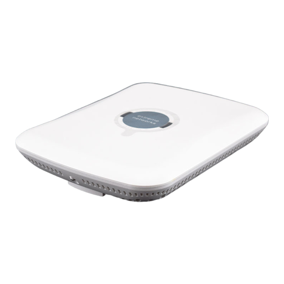
Introduction An Altitude™ 4600 Series Access Point links wireless 802.11a/b/g/n devices to the controller, enabling growth of your wireless network with a cost-effective alternative to standard access points. The Altitude 4600 Series Access Point provides two placement options: wall and ceiling. Wall mount slots fit onto two screws provided. Arrows on the case guide placement of the screws. -
Page 8: Warnings
Introduction Warnings Read all installation instructions and site survey reports, and verify correct ● equipment installation before connecting the Altitude 4600 Access Point to its power source. Remove jewelry and watches before installing this equipment. ● Verify that the unit is grounded before connecting it to the power source. ●... -
Page 9: Package Contents
Package Contents An Altitude 4600 Series Access Point comes in eight hardware configurations, four integrated (internal) antenna models and four external antenna models. The contents of the package differ between the integrated antenna model and the external antenna model. Both single and dual radio models are supported. External Antenna Models - Package Contents (AP4620-US, AP4621-US, AP4620-ROW and AP4621-ROW) - Page 10 Introduction One RJ-45 connector ● LED indicators ● Safety wire tie point ● Slots for wall mounting ● Clips for mounting on a suspended ceiling T-bar ● Lock port for Kensington® style Security Lock ● An Altitude 4600 Series Access Point has one RJ-45 connector supporting an 10/100/ 1000 Ethernet port and requires 802.3af-compliant power from an external source.
-
Page 11: Chapter 2: Hardware Installation
Hardware Installation Installation Instructions An Altitude 4600 Series Access Point mounts either on a wall with wide-shoulder screws or on a suspended ceiling T-bar. This unit is not designed for mounting on a desk. To prepare for installation, perform the following steps: 1 Match the model number on the purchase order with the model numbers in the packing list and on the case of the Altitude 4600 Series Access Point. - Page 12 Hardware Installation 4 Connect a CAT-5 or better Ethernet cable to a compatible 802.3af power source and run the cable to the installation site. Ensure there is sufficient slack on the cable to perform the installation steps. NOTE When operating in a Gigabit Ethernet environment CAT-5e or CAT-6 cable is required for Gigabit operation.
-
Page 13: Precautions
Orient the access point antennas vertically for best reception. ● ® To maximize the access point’s radio coverage area, Extreme Networks recommends conducting a site survey to define and document radio interference obstacles before installing an Altitude 4600 Series Access Point. -
Page 14: Wall Mount Hardware
Hardware Installation Wall Mount Hardware The following hardware is required to complete the wall mount of an Altitude 4600 Series Access Point: Two wide-shoulder Phillips pan head self-tapping screws ● Two wall anchors ● Security cable (optional) ● NOTE In the event the original mounting screws are lost, the following screws can be used: (ANSI Standard) #6-18 X 0.875in. -
Page 15: Integrated Antenna Suspended Ceiling T-Bar Mount Instructions
1 Orient the unit on the wall by its width or length. 2 Using the arrows on one edge of the case as guides, move the edge to the midline of the mounting area and mark points on the midline for the screws. 3 At each point, drill a hole in the wall, insert an anchor, screw into the anchor the wall mounting screw and stop when there is 1mm between the screw head and the wall. -
Page 16: External Antenna Wall Mount Instructions
Hardware Installation 1 If required, install and attach a security cable to the unit’s lock port. 2 Plug the Ethernet cable into the unit and to a switch with an 802.3af-compatible power source. 3 Face the bottom of the T-bar with the back of the case. 4 Orient the case by its length and the length of the T-bar. -
Page 17: Wall Mount Hardware
Wall Mount Hardware The following hardware is required to complete the wall mount of an Altitude 4600 Series Access Point (external antenna version): Two wide-shoulder Phillips pan head self-tapping screws ● Two wall anchors ● Safety wire (recommended) and a security cable (optional) ●... -
Page 18: Wall Mount Procedure
Hardware Installation Wall Mount Procedure 1 Orient the case on the wall by its width or length. 2 Using the arrows on one edge of the case as guides, move the edge to the midline of the mounting area and mark points on the midline for the screws. 3 At each point, drill a hole in the wall, insert an anchor, screw into the anchor the wall mounting screw and stop when there is 1mm between the screw head and the wall. -
Page 19: External Antenna Suspended Ceiling Tile (Plenum) Mount Instructions
The case has a safety wire tie point for a standard safety wire. CAUTION Extreme Networks does not recommend mounting an Altitude 4600 Series Access Point directly to a suspended ceiling tile with a thickness less than 12.7mm (0.5in.) or a suspended ceiling tile with an unsupported span greater than 660mm (26in.). -
Page 20: Suspended Ceiling Mount Hardware
Hardware Installation This placement requires installation of the provided light pipe for viewing the status lights of the unit. Suspended Ceiling Mount Hardware Light pipe ● Badge for light pipe ● Safety wire (recommended) and security cable (optional) ● Light Pipe Ceiling Tile Badge Ceiling Mount Procedure... -
Page 21: Altitude 4600 Series Antenna Options
14 Snap the badge onto the light pipe from the finished side of the tile. Altitude 4600 Series Antenna Options Extreme Networks supports two antenna suites for the external antenna model. One antenna suite supporting the 2.4 GHz band and another antenna suite supporting the 5 GHz band. -
Page 22: Software Version 4.X Led States
Hardware Installation The LED behavior is determined by the version of software running on the controller which the access point is connected to. The tables below show the LED patterns for software version 4.x and software version5.x. Software Version 4.x LED States Task 5 GHz Activity LED (Amber) 2.4 GHz Activity LED (Green) -
Page 23: Chapter 3: Specifications
Specifications Electrical Characteristics Both external and internal antenna model Altitude 4600 Series Access Point have the following electrical characteristics: Operating Voltage and Current: 48V DC, 180ma - 270mA An Altitude 4600 Series Access Point can receive power in one of following ways: 1 Power over Ethernet (PoE) - If your network is already set up with a Gigabit PoE injector (802.3af compliant), attach the LAN Ethernet cable to the access point’s LAN port. -
Page 24: Integrated Antenna Model Physical Characteristics
Specifications Weight 2.5 lbs / 1.13 kg Operating Temperature 32°F to 122°F / 0°C to 50°C Storage Temperature -40°F to 158°F / -40°C to 70°C Operating Humidity 5 to 95% Relative Humidity non-condensing Storage Humidity 85% Relative Humidity non-condensing Operating Altitude (max) 8,000 ft @ 28C Storage Altitude (max) 30,000 ft @ 12C... -
Page 25: Radio Characteristics
Radio Characteristics Both the integrated and external antenna model Altitude 4600 Series Access Points have the following radio characteristics: Operating Channels All channels from 4920 MHz to 5825 MHz except channel 52 -64 Channels 1-13 (2412-2472 MHz) Channel 14 (2484 MHz) Japan only Actual operating frequencies depend on regulatory approval for the country of use. - Page 26 Specifications Altitude 4600 Series Access Point Installation Guide...
-
Page 27: Chapter 4: Basic 4600 Series Configuration
Establishing Basic AP Connectivity This section defines the steps required to establish basic AP connectivity with an ® Extreme Networks Summit WM3000 series controller. Prerequisites for connecting an Altitude 4600 Series Access Point to a controller include: Ensure your controller has an appropriate access point capacity license. - Page 28 Basic 4600 Series Configuration An Altitude 4600 Series Access Points support the following DHCP vendor options: Code Description Format WLAN controller IP Address ASCII or String DHCP option 189 can be supplied with the DHCP Offer to provide an Altitude 4600 Series Access Points with one or more WLAN controller IP addresses which the Altitude 4600 Series Access Point will attempt to connect to.
-
Page 29: Chapter 5: Regulatory Compliance
The Extreme Networks Altitude AP4600 Series Access Points are manufactured by Motorola and are exactly the same as the Motorola model AP-650 Series Access Point except for brand name and product label. See the following link for Extreme Networks Declaration of Similarity (DoS) and Declaration of Conformity (DoC): http://www.extremenetworks.com/go/rfcertification.htm. -
Page 30: Radio Modules
Any changes or modifications to Extreme Networks equipment, not expressly approved by Motorola, could void the user’s authority to operate the equipment. Extreme Networks access points must be professionally installed and configured so that the Radio Frequency Output Power will not exceed the maximum allowable limit for the country of operation. -
Page 31: Country Selection - Note For Ap & Wireless Switch
WARNING! Operation of the device without regulatory approval is illegal. Country Selection - Note for AP & Wireless Switch Select only the country in which you are using the device. Any other selection will make the operation of this device illegal. The US version of the Access Point will only have US listed in the country selection table. -
Page 32: Ghz Only
Regulatory Compliance 2.4 GHz Only The available channels for 802.11 b/g operation in the US are Channels 1 to 11. The range of channels is limited by firmware. Health and Safety Recommendations Warnings for the use of Wireless Devices Please observe all warning notices with regard to the usage of wireless devices. Potentially Hazardous Atmospheres - Fixed Installations You are reminded of the need to observe restrictions on the use of radio devices in fuel depots, chemical plants etc. -
Page 33: Other Medical Devices
International The device complies with internationally recognized standards covering human exposure to electromagnetic fields from radio devices. For information on “International” human exposure to eletromagnic fields refer to the Extreme Networks http://www.extremenetworks.com/go/rfcertification.htm Declaration of Conformity (DoC) at Altitude 4600 Series Access Point Installation Guide... -
Page 34: Remote And Standalone Antenna Configurations
Regulatory Compliance Remote and Standalone Antenna Configurations To comply with EU RF exposure requirements, antennas that are mounted externally at remote locations or operating near users at standalone desktop of similar configurations must operate with a minimum separation distance of 20 cm from all persons. US and Canada Co-located statement To comply with FCC RF exposure compliance requirement, the antennas used for this... -
Page 35: Radio Frequency Interference Requirements - Fcc
Radio Frequency Interference Requirements - Symbol Technologies Inc. Tested to Comply With FCC Standards For Home or Office Use This equipment has been tested and found to comply with the limits for a Class B digital device, pursuant to Part 15 of the FCC rules. These limits are designed to provide reasonable protection against harmful interference in a residential installation. -
Page 36: Radio Frequency Interference Requirements - Canada
Regulatory Compliance Radio Frequency Interference Requirements - Canada This Class B digital apparatus complies with Canadian ICES-003. Cet appareil numérique de la classe B est conforme à la norme NMB-003 du Canada. Radio Transmitters For RLAN Devices: The use of 5 GHz RLANs, for use in Canada, have the following restrictions: Restricted Band 5.60 –... -
Page 37: Statement Of Compliance
Statement of Compliance Extreme Networks hereby, declares that this device is in compliance with the essential requirements and other relevant provisions of Directive 1999/5/EC. A Declaration of http://www.extremenetworks.com/go/rfcertification.htm Conformity may be obtained from Turkish WEEE Statement of Compliance Japan (VCCI) - Voluntary Control Council for... -
Page 38: Korea Warning Statement For Class B Ite
Regulatory Compliance Korea Warning Statement for Class B ITE Class B (Broadcasting This device obtained EMC registration mainly Communication Device for for home use (Class B) and may be used in all Home Use) areas. Other Countries Australia Use of 5 GHz RLANs in Australia is restricted in the following band 5.50-5.65 GHz. Brazil Regulatory declarations for AP-650 - BRAZIL Note: The certification mark applied to the AP-650 is for Restrict Radiation Equipment. -
Page 39: Chile
http://www.anatel.gov.br For more information consult the website Chile Mexico Restrict Frequency Range to: 2.450 - 2.4835 GHz. Taiwan NOTICE! According to: Administrative Regulations on Low Power Radio Waves Radiated Devices Article 12 Without permission granted by the DGT, any company, enterprise, or user is not allowed to change frequency, enhance transmitting power or alter original characteristic as well as performance to an approved low power radio-frequency devices. - Page 40 Regulatory Compliance Article 14 The low power radio-frequency devices shall not influence aircraft security and interfere legal communications; if found, the user shall cease operating immediately until no interference is achieved. The said legal communications means radio communications is operated in compliance with the Telecommunications Act.
-
Page 41: Korea
Korea For a radio equipment using 2400~2483.5MHz or 5725~5825MHz, the following two expressions should be displayed: 1 “This radio equipment can be interfered during operation.” 2 “This radio equipment cannot provide a service relevant to the human life safety, as it can be crossed”... - Page 42 Regulatory Compliance Altitude 4600 Series Access Point Installation Guide...
-
Page 43: Chapter 6: Waste Electrical And Electronic Equipment (Weee)
Networks for recycling. For information on how to return product, please go to: http://www.extremenetworks.com/go/eu-weee. http://www.extremenetworks.com/go/eu-weee Dansk: Til kunder i EU: Alle produkter skal returneres til Extreme Networks til recirkulering, når de er udtjent. Læs oplysningerne om returnering af produkter på: http://www.extremenetworks.com/go/eu-weee. - Page 44 Português: Para clientes da UE: todos os produtos no fim de vida devem ser devolvidos à Extreme Networks para reciclagem. Para obter informações sobre como devolver o produto, visite: http://www.extremenetworks.com/go/eu-weee. Slovenski: Za kupce v EU: vsi izdelki se morajo po poteku življenjske dobe vrniti podjetju Extreme Networks za reciklažo.
-
Page 45: Chapter 7: Customer Support
Customer Support NOTE Services can be purchased from Extreme Networks or through one of its channel partners. If you are an end-user who has purchased service through an Extreme Networks channel partner, please contact your partner first for support. Extreme Networks Technical Assistance Centers (TAC) provide 24x7x365 worldwide coverage.