Craftsman 247.885550 Owner's Manual
5 and 8 horsepower 24" and 26" width two stage track drive snow throwers
Hide thumbs
Also See for 247.885550:
- Owner's manual (41 pages) ,
- Operator's manual (45 pages) ,
- Operator's manual (44 pages)
Table of Contents
Advertisement
Quick Links
Advertisement
Table of Contents

Related Manuals for Craftsman 247.885550


Summary of Contents for Craftsman 247.885550
- Page 1 MANUAL MODELNOS. 247.885550 247.885680 ® 5 AND 8 HORSEPOWER 24" AND 26" WIDTH TWO STAGE Caution: TRACK DRIVE ReadandFollow SNOW THROWERS AllSafety Rules andInstructions Before Operating Assembly ThisEquipment Operation CustomerResponsibilities Serviceand Adjustment RepairParts...
-
Page 2: Safety Rules
n ,,,,,,, ....' u= '=,''= i=,=1=11 =,,n=H,...... SAFETY RULES ...., ,1=_== WARNING: TO REDUCE THE POTENTIAL FOR ANY INJURY, COMPLY WITH THE FOLLOWING SAFETY INSTRUCTIONS. FAILURE TO COMPLY WITH THE INSTRUCTIONS MAY RESULT IN PERSONAL INJURY. TRAINING •... -
Page 3: Product Specifications
Sears will repair, free of charge, any defect in material and workmanship. If this Craftsman snow thrower is used for commercial or rental purposes, this warranty applies for only 30 days from the date of purchase. -
Page 4: Table Of Contents
...... i U,l,lllllil,,,i i i Ul,ii ......TABLE OF CONTENTS ,llji ....iii, Ul,,i,iiiiiiiii Hill i,u, M I"III'H '1111' STORAGE .................. 17 SAFETY RULES ................PRODUCT SPECIFICATIONS ..........3 SERVICE AND ADJUSTMENT ......... 1 7 WARRANTY ................3 TROUBLE SHOOTING ............ -
Page 5: Shift Rod
ASSEMBLY INSTRUCTiONs ........ i i,,i IIIHII IIIIIII1,111,111,11,1 111111, IMPORTANT: This unit has been shipped WITH- Tools Required for Assembly: OUT GASOLINE or OIL, After assembly, see oper- 1/2" Wrench* ation section of this manual for proper fuel and (2) 7/16" Wrenches* engine oil recommendations. -
Page 6: Chute
,=,= i= ,, =,, ,=,,H ,,, ,=,,,,,,i,, ASSEMBLY INSTRUCTBONS , i11,,,1 1111 l=,,,r 1],,_1,1 HOWTOSET-UPYOURSNOWTHROWER WARNING: MAKE CERTAIN AND MOVED AWAY FROM THE SPARK SPARK PLUG WIRE IS DISCONNECTED PLUG BEFORE ASSEMBLING SNOW THROWER. ATTACHING THE HANDLE ASSEMBLY (Hardware A) ®... -
Page 7: Chute Crank
ATTACHING THE CHUTE CRANK (Hardware C) • Insert hex bolt through the upper chute crank bracket. See figure 4. e Place the hex bolt into the hole provided in the left handle. Secure with lock washer and hex nut. Do not tighten until after attaching the other end of the chute crank. -
Page 8: Clutch Cables
..=, = IH'"H ... =H=' 'I=HH= ..ASSEMBLY iNSTRUCTIONS =i Jill ll', m'H,='=,', "H l=' I' IMPORTANT: Attach the shift rod and clutch cables as follows. THEN CHECK THE ADJUSTMENTS AS I INSTRUCTED, AND MAKE ANY FINAL. ADJUSTMENTS NECESSARY BEFORE OPERATING YOUR SNOW THROWER. -
Page 9: Final Adjustments
nnn,n ASSEMBLY iNSTRUCTIONS ATTACHING THE LEFT AND RIGHT TRACK Traction Drive Clutch and Shift Lever Adjustment CONTROLS To check the adjustment of the traction drive clutch and shift lever, tip the snow thrower forward so that it • Remove the screw from the top of the right hand rests on the auger housing°... -
Page 10: Operation 1
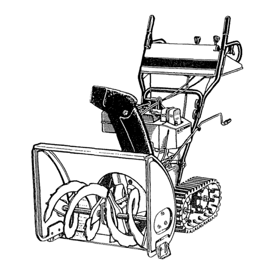
OPERATION i = i, = '='"=H",'H ' =,HI KNOW YOUR SNOW THROWER READ THIS OWNER'S MANUAL AND SAFETY RULES BEFORE OPERATING YOUR SNOW THROWER. Compare the illustrations with your snow thrower to familiarize yourself with the location of various controls and adjustments. -
Page 11: Handle
i i1,1 iiiiii1,1111r111 OPERATION iiiiiiiiiiiii1,,,111 ......i i iiiii1,11,11 i ui,ii, TRACTION DRIVE/AUGER CLUTCH LOCK (See figure The traction drive clutch is located on the right handle, Squeeze the traction drive clutch to engage the wheel drive. Release to stop This same lever also locks the auger clutch so you can turn the chute crank without interrupting the snow throwing process,. - Page 12 ,=,r=l ,,,H ...... H,,, =,,, OPERATION ..........= HiM=' " MI' BEFORE USING YOUR SNOW THROWER, AGAIN REFER TO THE "SAFETY RULES" AS SHOWN ON PAGE 2 OF THIS MANUAL ALWAYS BE CAREFUL, The operation of any snow thrower can result in foreign objects being thrown into the eyes, which can result in severe eye damage,, Always wear safety glasses or eye shields before starting power tool operation or while performing any adjustments...
-
Page 13: Fuel
OPERATION =N''HH==r',,' = = 'I=",'"="'"HH'=......... ,'=, H=,'=,Hm=I • To start a cold engine, push primer button one time_ Use a firm push. This step is not necessary e Remove fuel cap and fill fuel tank with about 3 when starting an engine which has been run for a quarts of clean, fresh, lead-free grade automotive few minutes. - Page 14 = H ,=, 'H"H,' ====='I NOTE: If the temperature is below 15°F,, additional priming may be necessary for initiaJ start only. ® Grasp starter handle and pull rope out slowly, until it pulls slightly harder° Let rope rewind slowly.. ® Pull starter handle rapidly. Keep a firm hold on the hand}e and allow it to rewind slowly.
-
Page 15: Customer Responsibilities
Check Engine Oil Change Engine Oil ..Service Air Cleaner ......, ..Spark Plug Muffler 1' CHECK GENERALRECOMMENDATIONS Shifting Mechanism WARNING: ALWAYS STOP THE ENGINE Lubricate the shifting mechanism and pivot points on AND DISCONNECT THE SPARK PLUG the shift rod with engine oil at least once a season or WIRE BEFORE PERFORMING... -
Page 16: Starting
,111,11,1,1 ii iii, CUSTOMER RESPONSiBiLiTiES iiiir,lrl ......ii i, iiiiii1,1111 iiiiiii AUGERS tighten securely_ Remove dipstick. If oit is not up to "FULL" mark on dipstick, add recommended oil, The augers are secured to the spiral shaft with two POUR SLOWLY, Wipe dipstick clean each time oil hex bolts and hex lock nuts°... -
Page 17: Storage
......... I= IH ,,,,,',,,,,,,,,,,I =......STORAGE • Drain the fuel tank_ Prepare your snow thrower for storage at the end of the season or if the unit will not be used for 30 days or ® Start the engine and let it run until the fuel lines and more carburetor are empty.. - Page 18 SERVICE & ADJUSTMENT i1,11,1 iii1,, iiiiiiii1,1111r,i ii i1,11,,,i BELT REMOVAL ANDREPLACEMENT WARNING: DISCONNECT THE SPARK I PLUG WIRE FROM THE SPARK PLUG I AND GROUND. To remove and replace either the rear or front auger Hex Bolts drive belt, proceed with the following instructions. Washers Hex Nuts •...
- Page 19 ........SERVICE & ADJUSTMENT iilii i iili iiiiii iiiiiiiiiiim, = Hum,==rHm==, iiiiii i llilill i ii illlli,ill iililllli liliill e If a replacement drive belt is needed, follow • Remove the six screws from the friction wheel previous instructions. Pull idler pulley up and lift assembly (three from each side)..
-
Page 20: Carburetor
SERV!CE & ADJUSTMENT 'UII=,I, 'n'Hn If adjustment is necessary, loosen the lock nut on the 5 H,P. ENGINE traction drive cable and thread the cable in or out as Idle Speed Adjustment. This screw is located on top necessary Tighten the lock nut to secure the cable of the carburetor and contacts the throttle To initially when correct adjustment is reached,, Reassemble the... -
Page 21: Shooting
============,== ==========1=,1== == n=,,=, TROUBLE SHOOTING GUIDE = ,== = ::::::::::::::::::::::::: ,nH,,= ,n,,l=l,H=.=r ....== Trouble Possible Cause(s) Corrective Action 1,, Fuel tank empty, or stale fuel. 1. Fill tank with clean, fresh gasoline° Engine fails to start 2, Blocked fuel line. 2. -
Page 22: Parts--Snow Thrower
SEARS CRAFTSMAN 5 AND 8 H.P. SNOW THROWERS MODEL NOS. 247.885550 247.885680 Repair Parts... - Page 23 SEARS CRAFTSMAN 5 AND 8 H.P. SNOW THROWERS MODEL NOS. 247.885550 Repair Parts 247.885680 PART PART D E'°"'P''0N DESCRIPTION 731-1317 Headlight Bezett 629-0058 Light Harnesst 731-1320 Upper Chute 684-0008 Shift Arm AsS'yr 731-1327 Handle Panel (247885550) 684-0022 Chute Crank Ass'y.
- Page 24 SEARS CRAFTSMAN 5 AND 8 H.P. SNOW THROWERS MODEL NOS. 247.885550 247.885680 Repair Parts • ®...
- Page 25 SEARS CRAFTSMAN 5 AND 8 H.P. SNOW THROWERS MODEL NOS. 247.885550 Repair Parts 247.88 e80 PART PART DESCRIPTION DESCRIPTION Hex Jam Nut 1/4-20 Thd, 712-0298 61840043 Dog Ass'y, #420 Chain--I/2 Pitch x 30 Links 713-0267 618-0044 Loll. Dog Ass'y, (Endless)
- Page 26 SEARS CRAFTSMAN 5 AND 8 H.P. SNOW THROWERS MODEL NOS. 247.885550 247,885680 Repair Parts 75 27...
- Page 27 SEARS CRAFTSMAN 5 AND 8 H.P. SNOW THROWERS MODEL NOS. 247.885550 Repair Parts 247.885680 PART PART DESCRIPTION DESCRIPTION NO,, 618-0120 710-0812 Worm Drive Ass'y. Comp¢ Hex Bolt 1/4-20 x ,75" Lg, (Gr 5) 6t8-0t21 712-0116 Hex Ins, L-Nut 3/8-24 Thd.
- Page 28 SEARS CRAFTSMAN 5 AND 8 H.P. SNOW THROWERS MODEL NOS. 247.885550 247.885680 Repair Parts...
- Page 29 SEARS CRAFTSMAN 5 AND 8 H.P, SNOW THROWERS MODEL NOS, 247.885550 Repair Parts 247.885680 PART PART DESCRIPTION DESCRIPTION 27 I 754-0431 "V"-Beltl" Engine--Tec. HSSK50-67353Nt i HSSK50-67353N ' HMSKS0-1555245 754-043O "V"-Beltl"t Engine--Tec, HMSK80-155524511 710-0627 Hex 5/16-24 x .75" Lg, !71040599 736-0242 Bell-Wash..345"...
- Page 30 SEARS CRAFTSMAN 5 AND 8 H.P. SNOW THROWERS MODEL NOS. 247.885550 247.885680 Repair Parts 4__ ! KEYi PART PART DESCRIPTION DESCRIPTION NO, i 631-0002 719_0295 Drive Wheel Ass'y. Track Housing 720-0223 631-0004 Idler Wheel Ass'y, Grip 683-0024 731-1292 Snow Track...
- Page 31 TECUMSEH 5 H.P. ENGINE MODEL NO. HSSK50-67353N Repair Parts 310_/1 307//; 305/! 93=_/ 287 390 370A 420/_...
-
Page 32: Parts
TECUMSEH 5 H.P. ENGINE MODEL NO. HSSK50-67353N Repair Parts PART CEY l DESCRIPTION QTY,, PART ITY. NOo DESCRIPTZON NO,, Ground Wire 110AI 35285 36469 Cylinder (lncL 2 & 20) 119 I 36443 Cylinder Head Gasket Dowel Pin 26727 120 i 36441 Cylinder Head (lncL 131) Oil Drain Extension... - Page 33 TECUMSEH 5 H.P. ENGINE MODEL NO. HSSK50-67353N Repair Parts PART PART DESCRIPTION QTYo DESCRIPTION QTY. 33333 Carburetor Cover Bracket 35499 "O" Ring 650735 35539 Screw, 10-24 x 3/8" Fill Tube Clip Lubrication Decal 35556 36261 Dipstick Control Decal 35282 34080 Spacer 370A Primer Decal...
- Page 34 PART DESCRIPTION QT_,, NO° Electric Starter (110 Volt) 33290D 31749 Retainer Ring 33522 Spring Retainer 33769 Anti-drift Spring Nut & Gear 33524 35911 Thrust Washer 35461 Drive End Cap Ass'y. (Incl.. 7) 35450 "O" Ring Armature 35912 35459A Housing Ass'y. 35452A Brush &...
- Page 35 TECUMSEH 8 H,P, ENGINE MODEL NO. HMSK80-155524S Repair Parts 298,_ 13 IA',,,_ 22,. "275 1_370A 200\ 370C 93 ¸...
- Page 36 TECUMSEH 8 H.P. ENGINE MODEL NO. HMSK80-155524S Repair Parts PART 3TYo DESCRIPTION PART DESCRIPTION Lock Washer 650880 35385 Cylinder (IncL 2, 20 & 72) 650881 Flywheel Nut Dowel Pin 27652 35135 Solid State Ignition 650820 Screw, 1/4_20 x 1/2" 610118 Spark Plug Cover 34171 Oil Drain Extension...
- Page 37 TECUMSEH 8 H.P. ENGINE MODEL NO. HMSK80-155524S Repair Parts PART DESCRIPTION QTYo PART DESCRIPTION QTY_ Carburetor Cover Muffler 35057A 35056 650765 Screw, 10-32 x t/2" 31588 Locking Plate 28942 792093 Screw, 10-32 x 3/8" Screw, 5/16-18 x 4-3/16" 34155 Fuel Tank Bracket 35985A Starter Cup Fuet Tank Bracket...
- Page 38 TECUMSEH 8 H.P. ENGINE MODEL NO. HMSK80-155524S Repair Parts PART DESCRIPTION QTY, 632334A Carburetor (lncL 184 of Engine Parts List) 631776A Throttle Shaft & Lever Assembly KJ°i I 631970 Throttle Return Spring 631778 Throttle Shutter 650506 Shutter Screw 632112 Choke Shaft & Lever Assembly 632174 Choke Shutter 630735...
- Page 39 TECUMSEH 8 H.P. ENGINE MODEL NO. HMSK80-155524S PART ..DESCRIPTION 33329D Electric Starter (I 10 Volt) 33842 Retainer Ring 33430 Spring Retainer 33431 Anti-drift Spring 33432 Gear 35893 Retainer & Nut (lncl.. 1) 35449 Drive End Cap Ass'y. (IncL 7) 35450 "O"...
- Page 40 ® [}ELNOS. Each snow thrower has its own model number° Each engine 247.885550 has its own model number. 247.885680 The model number for your snow thrower will be found on a label attached to the frame. model number for the engine will be found on the blower housing of the engine.