Table of Contents
Advertisement
Quick Links
Advertisement
Table of Contents

Related Manuals for Extron electronics SW AV


Summary of Contents for Extron electronics SW AV
- Page 1 SW AV Series Video and Audio Switchers 68-644-01 Rev. E 06 06...
- Page 2 Precautions Safety Instructions • English This symbol is intended to alert the user of important operating and maintenance (servicing) instructions in the literature provided with the equipment. This symbol is intended to alert the user of the presence of uninsulated dangerous voltage within the product’s enclosure that may present a risk of electric shock.
-
Page 3: Front Panel Controls
Quick Start — SW AV Series Switchers Installation Step 1 — Power down Turn off power to the input and output devices, and remove the power cords from them. Step 2 — Mounting If desired, mount the switcher in a rack or under a table. - Page 4 Quick Start — SW AV Series Switchers, cont’d Audio level indicators (Input 1 through Input 4 LEDs) each indicate a range of 6dB when lit: Input 1 LED: off = 0 db to 5dB, Input 1 LED: lit = 6dB to 11dB, Input 1 and 2 LED:lit = 12dB to 17dB, and so on.
-
Page 5: Table Of Contents
Autoswitch mode controls and indicators (video switchers) ... 3-5 Executive mode controls and indicator ... 3-6 ... 1-1 ... 1-2 ... 1-2 ... 1-2 ... 1-4 ... 1-4 ... 2-2 ... 2-2 ... 2-3 ... 3-2 SW AV Series Switchers • Table of Contents... - Page 6 ... A-5 Pre-cut cables ... A-6 Bulk cables All trademarks mentioned in this manual are the properties of their respective owners. SW AV Series Switchers • Table of Contents ... 3-6 ... 3-7 ... 3-9 single input ... 3-11 all inputs ... 3-11 ...
-
Page 7: Chapter 1 • Introduction
SW AV Series Switchers Chapter One Introduction About the Switchers Features... -
Page 8: About The Switchers
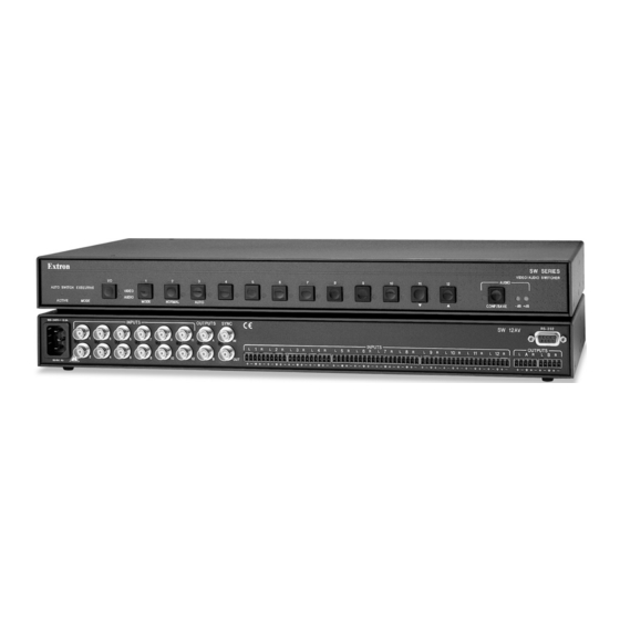
Introduction, cont’d About the Switchers The Extron SW AV series (figure 1-1) is a family of video and/or audio switchers with a wide array of input and output configurations, video formats, and audio connections. The switchers route S-video (luminance (Y) and chrominance (C)), and/or composite video, and/or unbalanced audio on RCA connectors, and/or balanced or unbalanced audio on captive screw connectors. -
Page 9: All Video Models
Bandwidth — Bandwidth is 250 MHz (-3dB). This high bandwidth allows the switchers to switch all of the quad standard video formats with no loss of signal quality. All video models Input sensing — The switcher continuously monitors all inputs to sense when the input signal is active or inactive. -
Page 10: Audio Switchers
Audio Inputs Low Audio Output Level Audio Inputs High Audio Output Level Figure 1-2 — Audio gain and attenuation SW AV Series Switcher • Introduction Consumer VCR SW SERIES VIDEO / AUDIO SWITCHER AUDIO AUTO SWITCH EXECUTIVE VIDEO AUDIO ACTIVE... -
Page 11: All Switcher Models
• Front panel controller — The SW AV series front panel controller supports touch-of-a-button input selection, audio gain and attenuation control, switch mode selection, and executive mode selection. - Page 12 Introduction, cont’d SW AV Series Switcher • Introduction...
-
Page 13: Chapter 2 • Installation
SW AV Series Switchers Chapter Two Installation Installation Overview Mounting the Switcher Cabling and Rear Panel Views... -
Page 14: Installation Overview
Secure the switcher to the rack using the supplied machine screws. Furniture mounting the switcher The SW AV switcher models can be mounted under a table or other horizontal surface with an optional Extron MBD 129 Through-Desk Mount Kit, part #70-077-02. -
Page 15: Cabling And Rear Panel Views
1U enclosures, but have more or fewer input connectors to accommodate the different configurations they provide. The two switchers shown have all of the connector types that are available in the SW AV product family covered in this manual. -
Page 16: Video Input And Output Connections (Video Models Only)
(A) models only) — Each input has a 3.5 mm, 5-pole captive screw connector for balanced or unbalanced stereo audio input. Connectors are included with each SW AV Series switcher, but you must supply the audio cable. See figure 2-4 to wire a connector for the appropriate input type and impedance level. - Page 17 • If the stripped section of wire is shorter than 0.2”, wires can be easily pulled out even if tightly fastened by the captive screws. SW AV Series Switchers • Installation Ring Sleeve (s) Ring...
-
Page 18: Remote Connection
External sync connection When the switcher switches between inputs, the resulting change in image should be glitch-free, or clean. Video models of the SW AV Series switcher can use an external signal to synchronize switching during the vertical interval. Without the external sync locking feature, switching between inputs can result in a brief rolling (sync loss) or a brief change in the picture size. -
Page 19: Power Connection
This type of video camera is capable of synchronizing with the external timing source for video editing applications. If no external sync timing source is connected to the switcher, switching occurs immediately after a front panel, RS-232, IR, or contact closure switch command. Monitor SW 12AV RCA... - Page 20 Installation, cont’d SW AV Series Switchers • Installation...
-
Page 21: Chapter 3 • Operation
SW AV Series Switchers Chapter Three Operation Front Panel Controls and Indicators Front Panel Operations Optimizing the Audio (Audio Switchers) Troubleshooting — If No Image Appears... -
Page 22: Front Panel Controls And Indicators
Operation, cont’d Front Panel Controls and Indicators The family of SW AV switchers have a wide variety of input buttons and other controls and LEDs that vary with the number of inputs and whether the switcher has video, audio, or both. Not all switchers have every control or indicator described in this chapter. - Page 23 EXECUTIVE VIDEO AUDIO ACTIVE MODE 13 15 Figure 3-3 — SW 12VA RCA front panel SW AV Series Switchers • Operation numbers); each callout is related to its SW SERIES VIDEO / AUDIO SWITCHER AUDIO CONF/SAVE SW SERIES VIDEO / AUDIO SWITCHER...
-
Page 24: Audio/Video Selection Control And Indicators (Audio Switchers)
Input 1 through 4, 6, 8, or 12 LEDs — The input LEDs identify the selected input. On models that switch both video and audio, if audio is broken away, the selected video input is indicated by a steadily lit input LED and the selected audio input is indicated by a blinking input LED. -
Page 25: Audio Controls And Indicators (Audio Switchers)
Auto(switch) button — The Auto button is used with the Mode button to select autoswitching mode. See Switch mode in this chapter. This button is a secondary function of the Input 3 button. -
Page 26: Executive Mode Controls And Indicator
An input can be selected for output using the front panel buttons. In switchers with both video and audio, the audio input can switch with the video input (audio follow) or either can be switched separately (audio breakaway). Select an input as follows: SW AV Series Switchers •... -
Page 27: Example 1: Select An Input
(Video AND audio switchers) Select to switch video, audio, or both by pressing the I/O button. Select the desired input by pressing the associated input button. Observe that the LED for the selected input lights or blinks (audio breakaway (Video AND audio switchers)). -
Page 28: Example 3: Select An Audio Input Only (Video And Audio Switcher)
Operation, cont’d Video switchers must be in normal (manual) mode. To select video only for the switch, if necessary, press and release the I/O buttons until the Video LED lights and the Audio LED is off. Press and release the input 4 button. The input 4 LED lights. The video on input 4 is now selected for output. -
Page 29: Example 4: Adjust The Audio Level
3-8, the LED readout shows a range of +6 dB to +11 dB. buttons to increase and decrease the audio LEDs flash to indicate each 1 dB level change. button, wait for the = off, = on, = blinking SW AV Series Switchers • Operation Press and hold CONF/SAVE AUDIO CONF/SAVE... - Page 30 The input LEDs stop displaying the audio level range, the +dB and -dB LEDs go off, and the selected input LED lights. 3-10 SW AV Series Switchers • Operation button repeatedly until the highest-numbered lit input button repeatedly until the highest-numbered lit input...
-
Page 31: Audio Level Reset - Single Input
To reset the audio level for an input to 0 dB, select the input: Video switchers must be in normal mode. (Video AND audio switcher) Select to switch both video and audio or audio only by pressing the I/O button. -
Page 32: Executive Mode (Front Panel Security Lockout)
Operation, cont’d Executive mode (front panel security lockout) Audio switchers have an executive mode that limits the operation of the SW AV switcher from the front panel. When the switcher is in executive mode, the I/O button (video/audio/video and audio selection), toggling between autoswitch and normal mode, and all of the front panel audio gain and attenuation functions are disabled. -
Page 33: Troubleshooting - If No Image Appears
Ensure an active input is selected on the switcher or that the switcher is in autoswitch mode. Ensure that the proper signal format is supplied. Check the cabling and make corrections as necessary. Call the Extron S Sales & Technical Support Hotline if necessary. SW AV Series Switchers • Operation 3-13... - Page 34 Operation, cont’d 3-14 SW AV Series Switchers • Operation...
-
Page 35: Chapter 4 • Remote Control
SW AV Series Switchers Chapter Four Remote Control Simple Instruction Set Control Windows-Based Program Control Contact Closure Control (SW4 and SW6 Models Only) Infrared Remote Control (SW4 and SW6 Models Only) -
Page 36: Simple Instruction Set Control
Remote Control Remote Control, cont’d The SW AV Series switchers can be remotely controlled via the switcher’s rear panel Remote (SW 4 and SW 6 models) or RS-232 (SW 8 or SW 12 models) connector (Figure 4-1). Remote control devices can be: •... -
Page 37: Switcher-Initiated Messages
The switcher-initiated messages are listed below: (C) Copyright 2002, Extron Electronics, SW AV Series, Vx.xx The switcher issues the copyright message and input selected message when it first powers on. -
Page 38: Symbol Definitions
Mute video Unmute video Read video mute SW AV Series Switchers • Remote Control 0 through the maximum number of inputs (0 = muted output) 1 through the maximum number of inputs 0 = no signal detected, 1 = signal detected... - Page 39 ZXXX •A* •F* V*004•A*004•F*1Vmt0•Amt0 nn-nnn-nn 60-484-22 1.23 SW AV Series Switchers • Remote Control Additional description Output no audio signal. Output selected audio input. Mute status = Set gain for input Set gain for input 4 to 3 dB. Set attenuation for input...
-
Page 40: Windows-Based Control Program
Push the SW AV Series Switchers • Remote Control icon in the Extron Electronics program group. button to refresh the input signal status. -
Page 41: Using The Help System
IR 102 Rx receiver box with 3' cable • External 12 VDC adapter power supply Install and operate the remote control in accordance with IR 102 User’s Guide (part #68-663-01) included with the remote. SW AV Series Switchers • Remote Control... - Page 42 Remote Control, cont’d SW AV Series Switchers • Remote Control...
-
Page 43: Appendix A • Specifications And Part Numbers
SW AV Series Switchers A ppendix A Specifications and Part Numbers Specifications Part Numbers... - Page 44 DC offset ... ±5 mV with input at 0 offset Switching type ... Vertical interval switching Sync Genlock connectors ... 2 BNC female (1 input, 1 loop-through) Standards ... NTSC 3.58, NTSC 4.43, PAL, SECAM SW AV Series Switchers • Specifications and Part Numbers...
-
Page 45: Audio Input
(100 mVrms), configurable Maximum level (Hi-Z) ... >26 dBu, balanced; >+20 dBu, unbalanced at 1% THD+N Maximum level (600 ohm) ... >21 dBm, balanced; >+15 dBm, unbalanced at 1% THD+N SW AV Series Switchers • Specifications and Part Numbers 2 dBu. -
Page 46: Sw Av Switcher Part Numbers
SW 6SV S-video switcher SW 6SVA S-video and audio switcher SW 6SVA RCA S-video and RCA audio switcher SW 6A audio switcher SW 6A RCA audio switcher SW AV Series Switchers • Specifications and Part Numbers ® ™ Part # 60-484-21... -
Page 47: Optional Accessories
MHR-2 SVM-M/20 (20 feet/6.1 meters) MHR-2 SVM-M/30 (30 feet/9.1 meters) MHR-2 SVM-M/50 (50 feet/15.2 meters) MHR-2 SVM-M/75 (75 feet/22.9 meters) MHR-2 SVM-M/100 (100 feet/30.4 meters) SW AV Series Switchers • Specifications and Part Numbers Part # 60-482-01 60-482-21 60-482-31 60-482-02... -
Page 48: Bulk Cables
BNC male RG6 crimp connectors, qty. 50 BNC bulkhead connectors, qty. 50 (for custom wall plates) Bulk cable in lengths up to 5000' is available with or without connectors. SW AV Series Switchers • Specifications and Part Numbers Part # 26-383-01 26-383-12... - Page 49 Note: This equipment has been tested and found to comply with the limits for a Class A digital device, pursuant to part 15 of the FCC Rules. These limits are designed to provide reasonable protection against harmful interference when the equipment is operated in a commercial environment.
- Page 50 Extron Electronics, USA 1230 South Lewis Street Anaheim, CA 92805 714.491.1500 www.extron.com Fax 714.491.1517 Extron Electronics, Europe Extron Electronics, Asia Beeldschermweg 6C 135 Joo Seng Road, #04-01 3821 AH Amersfoort PM Industrial Building The Netherlands Singapore 368363 +31.33.453.4040 +65.6383.4400 Fax +31.33.453.4050 Fax +65.6383.4664 ©...