
Related Manuals for PEERLESS LC SERIES


Summary of Contents for PEERLESS LC SERIES
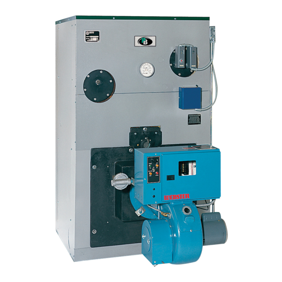
- Page 1 LC/LCE Gas/Off Boilers - Steam Installation, Operation Maintenance Manual PEERLESS ° CAST IRON BOILERS...
- Page 2 Sizes 4-24 Sections 4.75 to 32.5 Input Up to 83.7% Combustion Efficiency Forced Draft Venting • Only Requires a Three Foot Vent Above the Roof High Efficiency Power Burners • Choice ofBeckett, Carlin, Gordon-Piatt, Power Flame or Webster Integral Cast Iron Flue Collector...
- Page 3 Series LC/LCE pr=-r=-RLESS o Large Commercial Boilers • Packaged, Assembled Block or Individual Sections o Forced Draft Venting CAST IRON BOILERS Power Burners • Oil, Gas, Gas/Oil Q Steam or Hot Water Boilers Optional Tankless Coils Series LC Series LCE Net I=B=R Ratings 4 Efficiency...
- Page 4 SERIES LC SPECIFICATIONS F_[o]llll=l_ I_]]_r_l_J_.-][o_[,."]F_1Lqi] If.'1_ ][e[_ _[,,.'!1 Jacket Left of Distance Between Tappings* Floor to Jacket to Boiler C/L of C/L of Flue Model Width Flue Flue Size Length Top to Floor Number "A" "B" "E" "F" "GI" liG_l LC-04 37"...
- Page 5 SERIES LC/LCE SPECIFICATIONS STEAM PIPING Pipe the return line to a Hartford Loop, with the return nipple located from 2 to 4 inches below the normal water line. Minimum Minimum Header Model Header Model Number Riser Number Riser Size Equalizer Size Equalizer 3"...
- Page 6 SERIES LC/LCE SPECIFICATIONS Large, Integral Cast Iron Flue Collector Unique Flex-Seal Gaskets Tubular Heat Exchanger 613/4" Large Combustion Chamber Individual Draw Rods -- --_ 345,46,, Series LCE Includes HEATER HEATER LOCATION LOCATION LOCATION Cast lron Rear Cover Plate FRONT Heater No. Heater No.
- Page 7 SERIES LCE SPECIFICATIONS Rear Flue Cover Butterfly Flue Damper (Series LCE) Mounted Horizontally or Vertically Cast Iron Block Assembly-Top Flue Outlet 4_/,_ " • .* 4,_,_¢ 16'_1(_ 4" SupplyTappings <D I (_) 3" Rear ReturnTapping • I=.=._o 3" Side Returns 63"...
- Page 8 SERIES LC/LCE BOILER SPECS Water • Cast Iron Sections- Factory Boiler Approx. Tested • High Limit,Manual Reset Model Shipping • Flex-Seal Gaskets • Operating Control Number Width Length Height Wt. (Ibs.) • Combination • Wet Base Desi_.. 50 PSI W.P. LC_4 78"...
- Page 9 VENTING USING THIS MANUAL A. INSTRUCTION MANUALS ....INSTALL THE BURNER B. SPECIAL ATTENTION BOXES ... A. BURNER APPLICATION ....PREINSTALLATION B. INSTALL BURNER MOUNTING PLATE ..27 C. MOUNT THE BURNER ....A. ACCESSIBILITY CLEARANCES ..B. CLEARANCE FROM COMBUSTIBLE CONSTRUCTION .....
- Page 10 r*_l IL_['-'_I/:tII_/[e]L_I LvJ¥±_L_I r-'_ The Series LC/LCE Installation, Operation & Maintenance Manual is divided into four basic sections: I. Preinstallation (Section I) 2. Installation (Sections 2 through 8) 3. Start-Up (Section 9) 4. Maintenance (Section 10) _.'_'.,I:[_P_I! F-_III:IL_Ii[O]L_I ;{*):4:[, Indicates a condition or hazard which may cause severe personal injury, death or major property Throughout this manual you will see special attention...
- Page 11 Theequipment mustbeinstalled inaccordance withinstallation r equirements oftheauthority h aving jurisdiction or,intheabsence o fsuchrequirements, to thecurrent e dition ofthe National Fuel Gas Code, ANSI Z223.1/NFPA 54. Where required by the authority having jurisdiction, the installation must conform to American Society of Mechanical Engineers Safety Code for Controls and Safety Devices for Automatically Fired Boilers, ASME CSD-I.
- Page 12 oN [*.]-'liLVJlk_l:i'4[a):] L vJq_l Inspect the existing chimney or vent system Make sure it is in good condition• Inspect chimney liner Provide the following minimum clearances to and repair or replace if necessary• combustible construction• See Figure i. Sides: 6" The vent system and installation must be in accordance with the current edition of the American...
- Page 13 FOUNDATION LENGTH JACKET LENGTH SECTION LENGTH Steel Channels, Supplied in Baffle Carton Leg Locations Figure 4: Foundation Layout Exterior Vents: I=lli :{0] II =1 ;_ _-'1:11/ I_f{ a) Insulate sufficiently to ensure adequate draft and If the boiler room floor is not level or if additional to prevent vent damage due to condensation.
- Page 14 Table 1: Foundation Lengths :Pl gA=1 ." t I_i_[o] L'_ I:,[o1 L_ I =1 L_ i iI_ Model Foundation Length, Inches Packaged: All components should be inside crate. In some cases the burner may be shipped separately, Optional equipment, such as barometric draft LC-04 37"/_, dampers, may also be shipped separately.
- Page 15 Table 2A: Series LC Shipping List Baffle Assembly Kit Ctns. Flue C_. Jacket Cartons (TblSOpttom} Standard Sections Table 3 for Optionsl 1" Boiler Channel Carton Top'Side Contents Contents Front/Rear Panels Model Rail Plain LWCO 3" Tap. (_ Table 4 S¢¢ Below See Below _nels Hardware...
- Page 16 Table 2B: Series LCE Shipping List Standard Sections (See Table 3 for Optionsl Barge Assemb]_ Cartons Flue Ctn. Jacket Cartons Table 5 Io_ Omionsl Ctn. Top Std. Boiler Channel 1" Carton FIo_ P_rt Gas]_ets Silicone Sea_nt, ¢onlents Fmn_Rear Panels Model J Rail Flue LWCO...
- Page 17 Table Standard Optional Sections Knockdown Boilers 15 psig Steam MAWP Sections Standard wflnspectionTappings Part # Stock Code Pad # ITPStock Code Front LC-1001 86000 LC 1013 86010 Intermediate LC 1000 86004 LC-IO14 86014 LWCO Intermediate LC-IO00-1 86008 LC 1014 2 86092 LCE-1064 86110...
- Page 18 Table Burner Mounting Plates Boiler Model Model LCE-13 LCE-14 LCE-15 LCE-16 LCE-17 LCE-18 LCE-19 LCE-20 LCE-21 LCE-22 LCE-23 LCE-2 CF2300AKG 86074* CF2300AKB 86083* 86083* Beckeit CF2500 86074* 86074* Available CF35(K)ARM 86083* 86083* 86083* CF3500PJKL 86080* 86080* 80ICRD 86073 86073 Carlin 1050FFD .
- Page 19 Rear Flue Box Figure Series LC Boiler Assembly - Right Side View...
- Page 20 Rear Flue Flue € Cover ® > O" < o...
- Page 21 Remove lifting frame and hardware. 1:,.',_'_€,.][9_,'_€"1:=1,_] i:{*]llq_: Proceed to Section D: Install Coils or PLates 1. Remove crate top and sides. Remove any loose cartons. Remove burner support pedestal [,.)q 114i_[.I1,,][4 mlmlh_lk'_l i=(,,]l!_: nipple, if supplied. 2. Lift boiler off crate pallet. Move to location Place channel rails as shown in Figure 4.
- Page 22 Recess Flat'_ Machined Machined The sections are heavy and must be supported o?:eo Ji Face securely. I0. Lift up the Rear Section and move into position the steel channels on the boiler foundation. 11. Screw a 3" pipe at least 30 inches long into the lower 3"...
- Page 23 SECTIONS ARE TOP HEAVY. HANDLE WITH CARE TO AVOID TIPPING OR FALLING. Intermediate tion Level Each Section: Place the first intermediate section next to the rear section Spirit as shown. Use a spirit level to .=vel make sure the sections are plumb.
- Page 24 I "]av_..]_ ii'l_ [:7_]TI :I;1 16. To propedy assemble LC/LCE sections in the field. 17 Repeat with the remaining sections. the following steps must be followed to ensure that Save the LWCO Intermediate with two I" no damage occurs to the tie rod lugs. A 0-I00 ftdbs tappings (for level control) for use as the section torque wrench is required•...
- Page 25 l_nP_j :I=I I_[o_ SERIES SERIES Fron_ Aear Front 13 IZ H 10 9 e 5 4 3 _ _ Rear iiill Front Rear iiii Front Rear Fro_t _ I_ 13 12 _1 _0 9 n 7 6 5 _ 3 Rea_ Fron_ 16 15 _...
- Page 26 III:(_i i/.l-, :_']f!_" JR ILl'_[_ Ir'.._ UH N Il {_o]lNl_,,_ [o];| I_IIF,.._IUI:::F_ =I lii'i.];{o]_lL'l|[@/1511/II1:1.]1111 Remove the coil cover plates, gaskets and mounting 1. Install a drain valve in the Rear Section, Tapping 13 hardware, located in the Flue Box Carton• See Figure 29.
- Page 27 Table Taokless Coil Ratings Heater No. Heater No. Heater Two Heaters No. Two Heaters Two Heaters No. X-1020 X-1021 X-1022 X-1020 X-1021 X-1022 Model Location Location Location Location Location Location LC-04 LC_05R LC 05 LC-06 6.25 7.75 LC-07 1375 LC-08 9.25 14.5 I &...
- Page 28 I_I'_"]51k117=I .l.l_.]Ir:l_ ;IN r±_'.l;,,lN_"ie,]il_±_L_[olnnluu_e_v,a:l; _I'.lW'.._und=l Cleanout Cover Plate With Insulation I. Apply the Cleanout Cover Plates on the tops of the section joints as shown in Figure 15. Pre-assemble a steel fiat washer and steel nut on the carriage bolts. Place a carriage bolt into each side of the cleanout opening as shown in the figure.
- Page 29 II: _ h__'_ ir_,_ tl m etUJ ::It:f_,!-t ;l l:_ ii _ h,_ F:-II f :'_ I! ql_ : F,__/_ I :] ::h| III i'll_ i Remove the Front Cleanout Plate from Front (LCE) Remove ceramic fiber liner from jacket Section.
- Page 30 ;,]1fl::1 i_ :1:1:1_,]]1[_- Counterflow Gravity systems require the boiler steam IiI; t _1 ",I:I -'!:!1/ [*] L _ line to enter the top of the steam main. See Figure 20 for this special case. The boiler must be pressure tested as outlined in the chapter "Place the Boiler Sections"...
- Page 31 On pumped return systems, install a boiler cock after the pump to allow throttling of the pump discharge. The pressure after the boiler cock should be no more than 5 psig above the boiler operating pressure. Boiler Riser Piping Pumping the water into the boiler too fast will cause enters TOP of main collapse of the water level and level control problems.
- Page 32 I ;1I_ _ _ -i-i-i-i-i-i-i-i-i_ _ _I LCE-13 THRU LCE-24 TWO END RISERS ONE OR MORE INTERMEDIATE RISERS RETURN CONNECTIONS Figure 21: Supply and Return Piping - Pumped Return and Parallel Flow Gravity Systems...
- Page 33 l_1_llill _ I;I.]TI-_;t Steam Supply Stop Valve Pipe All Headers Minimum 24" Above Boiler Water Line Stop Valve Blowdown Valve Figure 22: Piping Multiple Boilers, Typical, Gravity Return Systems Steam Stop Supply Valve Pipe All Headers Minimum 24" Above Boiler Water Line Stop Valve _f_\_...
- Page 34 "_1 "J,| :1_:_ H _ //'l:I _:! ;| | Attach the Middle Front Panel and Lower Front Rail in the same manner. Collect all the jacket cartons: Jacket Front & Back Position the Jacket Assembly with the front panels Carton plus Jacket Side &...
- Page 35 Jacket Top Panel Jacket Top Panel Jacket Top Rear Panel Jacket Rear Panel • I Jacket Top Rear Panel Jacket Top Jacket Front Panel Side Panel Jacket Front Jacket Top Panel Side Panel Jacket Front Middle Panel Side Panel Jacket Left Support Front...
- Page 36 Refer to Chapter I, preinstallation, Section D. Chimney, or Vent for installation requirements. Refer to Chapter 9. Startina the Boiler, Section C. Run Burner Check Out for damper settings and draft requirements. Screw (7) 3/8"-16 x 21/4"studs into the holes in the I:{II:|L_I:I;t r:1:J'Jl[l'Y:_li[e]{ front section around the chamber...
- Page 37 Figure 26: Combustion Chamber Layout - See Table 13 for Dimensions Table Combustion Chamber Dimensions Chamber Burner Front Plate Extension Past Jacket (Inches) Model Length "A" Gordon- Power (Inches) Beckett Carlin Piatt Flame Webster LC-04 61/s LC-05R 23W16 LC-05 23_5Ao ll/s LC-06 LC-07...
- Page 38 [_o]_ h'_ 1 :(..in uI _LIJ =lml [ "_ 1"J_c7 Read the Burner Instruction Manual, supplied with the boiler or with the burner if purchased separately. Review applicable code requirements for burner and To Gas Supply --_ fuel piping installations. Install piping to allow removal of burner and access to combustion chamber...
- Page 39 Table 14: Capacity of Gas Supply Pipe in Cubic Feet Per Hour of Natural Gas for Pressure Drop of 0.3 inch Water Column, Pipe Length 1-1/4" 1-1/2" 2" 2-1/2" 3" 4" 6 t, (Feet) Pipe Pipe Pipe Pipe Pipe Pipe Pipe 1050 1600...
- Page 40 Ih_[..'_lf;11lll _',]r;1;;l::illk'4LVl;1IkvJ=[.. ID31 IIs_[_"]llr;!llt!I;,l:?:k."_'_lJ:|::l[I,[i]_//:(t]l_ 3. Pipe the Steam Pressure Gauge and Boiler Limit and Pipe the Pop Safety Valve on a tee mounted in the 2]/2'' tapping located on the upper ]eft side of the Operating Pressure Controls as shown in Figure 30. Rear Section.
- Page 41 Install all line voltage wiring in conduit ¢H h_l.."l Ih_1 I ! IKa,(o] _ilII; {o] INr_,_i I; i h_[_. Do not install single pole switches, including safely Wire the boiler according to the wiring diagrams controls, in a grounded line. supplied with the burner and the boiler (in the Boiler Envelope) 2.
- Page 42 11;< FRONT REAR 4" NPT Supply Tapping, Front Section Not Used On Steam, 3/4" NPT - Plug Pressure Ctrl/Gauge Assembly, 4" NPT Supply Tapping, Rear Section 3/4" NPT Tapping 3" NPT Return Tapping, Rear Section Secondary Probe LWCO Tapping, 3/4" NPT Not Used On Steam, Not Used On Steam, 1"...
- Page 43 . ]_[--_t'_] _ ['_k'i]_ - o_I_]_], _J;th'_l [:1_JIfll_[_ Option 1 (Right Hand Shown, Left Hand WouEd Be Reversed) Option 2 3/4" X 3/4" X 1/4" Reducing Tee, Malleable 3/4" x4" Nipple, Black Iron 3/4" x 5" Nipple, Black Iron 3/4" Cross, Malleable 3/4"...
- Page 44 Burner Cut-Off Level /> 1/2" Brass Union Conduit Connection 1/2" Brass Close 1/2" X 4" Brass Nipples (2 Req'd) Nipples (2 Req'd) Figure 31: Optional Model 67PE2 Float Low Water Cutoff 81/2 '' Normal Water Line Burner Cut-Off Level Feeder Closing Level (Mark on Casting) Figure 32: Optional...
- Page 45 74;,] Ii;1177f4lTffitI 4 Burner Cut-Off Level Casting) Normal Water Line LWCO Intermediate Section (First from 12" Boiler Foundation Install 1" Blowdown Valve 1" Cross I" x 3" Nipple 1" x 12" Nipple 1" Ground Joint Union I" x 4" Nipple 1"...
- Page 46 Burner Cut-Off Level is 1V2" Below Center Line on 51-2 and 51-S-2 Controls (23/4 " Below Normal Water Line) Feeder Closing Level (Mark on Castingj Normal Water Line Control Center Line LWCO Intermediate Section ( y_Bo!le[ Foundation Install 1" Blowdown Valve SUGGESTED FITTINGS...
- Page 47 3/4" Control High Temperature Tapping Hot Water Provide anti-scald devices in the system where needed. Mixed Water Tankless Failure to control water Heater temperature to showers or other usage areas Flow where a scald risk exists can result in severe personal injury, Cold Water...
- Page 48 When a barometric draft regulator is installed in the "-!1 [_:l_[li:l; I']l'J h_[4 venting system, adjust the boiler damper for 0" wc pressure reading at the damper. Adjust the draft Steam Piping regulator for -005" wc draft between the boiler a) The Boiler must have been hydrostatically tested.
- Page 49 The boiler must be cleaned to remove any 9. Open the make-up water valve to coninuously feed water to the boiler, Allow water to flow out the skim accumulation of oil, grease, sludge, etc. that may be in the system. These substances can cause foaming tapping.
- Page 50 c) Do not use ethylene glycol antifreeze in a steam boiler or system. Do not store or allow combustible or flammable d) Be certain that the boiler and system are refilled materials near the boiler. Substantial fire or explosion before returning to service. Follow the hazard could result, causing risk of personal injury, Instructions in the manual and the Lighting death or property damage.
- Page 51 Remove the Burner and Burner Mounting Plate. !::lq I e7,_11 k"m Lvj F±I I L_ / | _ L_ _:1 _ [o4 Remove any scale or soot from the combustion chamber by means of vacuum cleaning or other Inspect the boiler area to make sure the area is free available means.
- Page 52 Table Series LC/LCE Boiler Ratings -'1 _ :11_.'II I(l_J Kil =1 :(011i 1 :tl :q:_ | I_[€_ Gross l B R Burner Capacity I B R Net Ratings Combustion Efficiency Boiler I=B=R Boiler Steam Steam Water Model Output Number Sq. Ft LC-04 16.3 1708...
- Page 53 -IT[,]IIII ::1 ;] IT_'__ d T_[_._ [_ t_bSl :l_-_]J[O]_ _ -_] Flue 4" Supply Tappings 3" Side Return, when required Connection 3" Rear Return Tapping Rear Observation Port 3" Intermediate Supply Tap, when required ® Maximum PowerFlame: 36" 29 = Burner Gordon-piat_: 32"...
- Page 54 Table 17: Series LC/LCE Boiler Dimensions 1-1iI I ,,t-i ,_-TI,%wl I *|',| l ¶ ? t| -d•u , -'*"." LO]_h" Jacket Supply Piping Return , Riser Tapping Locations* Vent Location Vent Boiler End Sect. I Burner Recom. iping Tappings _ Intermediate Section Tapping Center...
- Page 55 _._. _.-© ca- r _.('3...
- Page 56 L_:I;/-_ If] i_-,_'ii-"]- Table 18A:Series LC Repair Parts Front Section See Table 3 for Stock Code Intermediate Section w/1 '_Tapping Intermediate Section Back Section Tapped Intermediate Section 51671 2 Required per Flueway ' Upper Flow Port Gasket Lower Flow Port Gasket 51672 I Required per Flueway 51721...
- Page 57 I;1=]_'-_I.qI ",7_'_ ;tl_'_ Table 18B: Series LC Repair Parts (continued) Top Jacket Panel LC 6004 For Models LC-04 and LC 08 Top Jacket Panel LC6004 For Modds LC 05. LC 08, LC-09 and LC 10 Top Jacket Panel LC 6004 2 For Models LC-06, LC 10.
- Page 58 ,,.i...
- Page 59 Table 19A:Series LCE Repair Parts See Table 3 for Stock Code Front Section Top Flue Outl#t Inteml#dlat¢, S_'ctlon intermediate Sechon Tapping [ntermedlate Section Back Sertlon Closed Back Back Section _/Tankless Cod Opening Tapped Intermediate Section Upper Flow Port Gasket 2 Required per Flueway 51671 Lower Flow Port Gasket i Required per Flueway...
- Page 60 Table 19B: Series Repair Parts (continued) For Models LCE-15, -16, -19, 23 & 24 Top Jacket Panel LC-6004-2 For All LCE Boilers Top ,Jacket Panel with Flue Opening LC-6022 Rear Top Jacket Panel LC-6006 51132 For Models LCE-13 through LCE-17 Top Flue Outlet Plate (14"...
- Page 61 Series LC/LCE Gas/Oil Boilers Oil, Gas Steam Installation, Operation Maintenance Manual TO THE INSTALLER: This manua/ is the property of the owner and must be affixed near the boifer for future reference, TO THE OWNER: This boiler should inspected annuafly Quafiffed Service Agency.