Advertisement
Available languages
Available languages
Advertisement
Table of Contents

Related Manuals for Kenmore ELITE 233.52363200


Summary of Contents for Kenmore ELITE 233.52363200
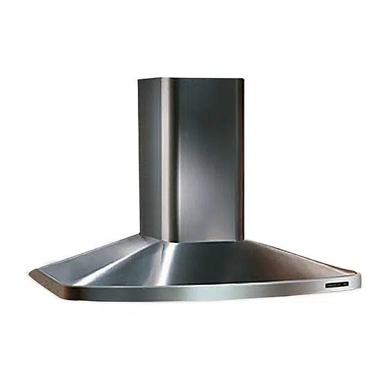
- Page 1 Use & Care / installation Manual pana Manual de uso y cuidado /instalaci6n Models 233.52303200 (3o" wide / 76,2 cm de ancho) Modelos 233.52363200 (36" wide/91,4 cm de ancho) 233.52423200 (42" wide/106,7 cm de ancho) Sears, Roebuck and Co,, Hoffman Estates, HL60179 U,S,A, www,sears,com...
- Page 2 WARNING WARNING SUITABLE HOUSEHOLD TO REDUCE THE RtSK OF INJURY TO PER- COOKING AREA. SONS IN THE EVENT OF A RANGE GREASE FIRE, OBSERVE THE FOLLOWING:* TO REDUCETHE RISK OF FIRE, ELECTRICAL 1. SMOTHER FLAMES with a close=fitting lid, SHOCK, OR INJURY TO PERSONS, OBSERVE cookie sheet, or metal tray, then turn off the...
- Page 3 PREPARE THE HOOD Unpack hood and check contents_ You should receive: 1 - Hood 1 - Decorative Flue Assembly 1 - Parts Bag containing: 1 - Mounting Bracket 1 - Discharge Collar 1 - Flue Mounting Bracket 8 - Mounting Screws (4,8 x 38mm Pan Head) 5 - Mounting Screws (3,9 x 9,Smm Pan Head) 8 - Drywall Anchors 1 - Installation Instructions...
-
Page 4: Install The Ductwork
INSTALL THE DUCTWORK ROOFCAP NOTE: To reduce the risk of fire, use only metal ductwerk, 1. Decide where the ductwork will run between the hood and the outside. 2. A straight, short duct run will allow the hood to perform most efficiently. 3. - Page 5 MOUNT THE PLATE PLATE OF Mount the plate of the electricaI system attaching it with 3 screws, ELECTF_AL SYSTEM WIRING Note: This range hood must be properly grounded.The unit shoumd be installed by a qualified electrician in accordance with all appHcabme national and mocalelectricam codes.
-
Page 6: Connect Ductwork
CONNECT DUCTWORK FLUE M OUNTtNG BRACKET Ducted Configuration MOUNTENG SCREWS 1. Adjust the width of the flue mounting bracket to equal the inside width of decorative flue. insert tighten mounting screws to hold bracket width. 2. Use mounting screws and wall anchors to secure flue mounting bracket to the... - Page 7 Non-ductedrecirculation Configuration FLUE MOUNTING 1. Adjust the width of the flue mounting BRACKET bracket to equal the inside width of MOUNTENG SCREWS decorative flue. insert tighten mounting screws to hold bracket width. 2. Use mounting screws and wall anchors to secure fBue mounting bracket to the...
-
Page 8: Maintenance
NON°DUCTED RECmRCULATmON FILTER mNSTALLATmON 1. Purchase a charcoal filter (B03300488) from your dealer. 2. InstalI the filter by pressing the 2 tabs on the filter down into the speciaI housing and rotating upward. FILTER MAINTENANCE Proper maintenance of the Range Hood wilI assure proper performance of the unit. -
Page 9: Operation
OPERATION UGHT SWrrCH BLOWER Controls SWrrCH The hood is operated using the slide controls PILOT under the bottom of the hood. LAMP The light switch turns the lamps on and off. The blower switch :makes it possible to select the motor operating speed. Position O: motor off. -
Page 10: Warranty
WARRANTY Hfwithin 1 year from the date of installation, any part of this range hood fails to function properIy due to a defect in material or workmanship, Sears will repair the part or furnish and install a new part, free of charge. FULL 30_DAY WARRANTY ON F_NtSH ON PAINTED OR BRIGHT METAL PA RTS... - Page 11 INDICADO P ARA ELUSOENCOCINAS PARA EVlTAR EL RIESGO DE DANOS DOMESTICAS. PERSONAS EN CASO DE FUEGO POR ALTO NIVEL DE GRASA, TENGA EN CUENTA SIGUIENTE:* PARA EVlTAR EL RIESGO DE iNCENDIO, 1. SOFOQUE LALLAMA con unatapadera apropiada,una CORTOCIRCUITO DAI_O PARA bandeja metbJica 6 un utensilio de coc[na qu.epueda PERSONAS, OBSERVE...
- Page 12 PREPARE LA CAMPANA Sacar la campana de I'embalaje y controlar el contenido. Recivireis: 1 - Campana 1 - Tubo decorativo 1 - Bolsita con: 1 - Soporte de montaje 1 - CasquilIo 1 - Soporte para e! montaje de! tubo 8 - Tornillos de montaje (4,8 x 38mm cabeza redonda) 5 - Tomillos de montaje (3,9 x 9,5ram cabeza redonda) 8 - Escarpias...
- Page 13 mNSTALACION DEL TUBe EXTRACCION NOTA: para evitar emriesge de incendio, TUBO use seiamente material de metal 1. Decida donde va a colocar e! tube de extracci6n entre Ia campana y Ia parte exterior. -/-_ ._jrAPA 2. Un recorrido de tube corto y recto permitira...
- Page 14 INSTALACION DE LA PLACA PLACA DEL S_STEMA Montar Ia placa deI sistema electrico fij_ndoJa ELECTR_O mediante tres tornillos. INSTALACION ELECTRICA Nota: Este tipo de campana tiene que set conectada a tierra cuidadosamenteo unidad debe instamarla tecnico electricista siguiendo mas norrnas nacJonalee y locales, INSTRUCCIONES DE CONEXION...
- Page 15 ENTUBADO SOPORTE MONTAJE [}EL TUBO CANAUZACmON TORNILLOS MONTAJE Configuraci6n con tubo 1. Regule el soporte de montaje del tube de manera que su ancho coincida con el de! tubo decorativo superior. CoIocar y fijar los tornillos de montaje para que el soporte se adapte a dicho ancho.
- Page 16 Configuraci6n sin tubo SOPORTE 1. Regule el soporte de montaje deI tube MONTAJE DEL TUBO TORNtLLOS de manera que su ancho coincida con el MONTAJE deI tubo decorative superior. Co!ocar y fijar los tomilIos de montaje para que el soporte se adapte a dicho ancho. 2.
- Page 17 mNSTALACmON DEL FJLTRO (CONFJGURACJON SIN TUBO) 1. Compre un filtro al carb6n (B03300488) a su proveedor habitual. 2. Instalen el filtro Jntroduciendo Ias dos RLTROAL JengOetas del filtro en el alojam[ento tal efecto y haciendo que gire hacia arriba. MANTENJMJENTO Un mantenlmiento adecuado de Ia campana asegura el funcionamlento...
- Page 18 FUNCmONAMIENTO _NTERRUPTOR Mandos DELASPERADOR ENTERRUPTOR DA LUZ La campana se controla mediante mandos corrrederos situados en la parte P_LOTO inferior de Ia misma. El interruptor da luz enciende y apaga las I_mparas. °© El interruptor del aspirader: regula velocidad de trabajo del motor= Posici6n O: 0123 motor apagado, El piloto se enciende cuando el aspirador...
- Page 19 GARANTIA Si dentro de 1 a_o de Ia fecha de Ia instalaci6n, cualquier parte de esta campana de cocina deja de funcionar en forma apropiada debido a defecto en el material o la mano de obra, Sears reparar_ la pieza afectada o proveera e instaiar_ una pieza nueva libre de cargo.
-
Page 20: Service Parts
SERVICE PARTS MODELS 233.52303200 _ 233.52363200 = 233.52423200 KEY NO. PART NO, DESCRiPTiON B08087294 Grease FiIter B02300233 Motor Capacitor BE3345170 Electrica! Box Support B03295005 Terminal Box B02300722 Halogen Lamp Bulb BWO000019 Blower B02310187 Motor B03295076 Blower Wheel B03202007 Rubber Washer B02300249 Feeder Cable B08091462... -
Page 21: Lista De Piezas
LISTA DE PIEZAS DE FiECAMBIO MODELOS 233.52303200 - 233.52363200 - 233.52423200 CODo No PtEZA No DESCRJPCI6N B08087294 Filtro antigrasa B02300233 Condensador BE3345170 Soporte de Ia caja de instalaci6n electrica B03295005 Caja del cuadro electrico B02300722 L&mpara hal6gena BWO000019 Convoyador B02310187 Motor B03295076 ManilIa de! motor... - Page 22 SERVICE PARTS - USTA DE PIEZAS DE RECAMBIO MODELS 233.52303200 - 233.52363200 o 233.52423200 B02300674 474 4_...
- Page 23 repair of major brand applicances in your own home °.. no matter who made it, no matter who sold it! 1-800-4-MY-HOME ® Anytime, day or night (1-800-469-4663) (U.S.A. and Canada) www.sears.com www.sears.ca For repair of carry-in products Iike vacuums, Iawn equipment, and electronics, cail for the nearest Sears Parts and Repair Center.
- Page 24 04306898...