Table of Contents
Advertisement
Operator's
Manual
CRAFTSMAN
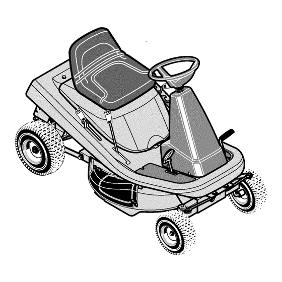
Mid-Engine Rider
13.5 HP. Electric Start
30" Mower / Mulcher
Variable Speed
Model 536.270270
• Safety
• Operation
• Maintenance
• Parts
CAUTION:
Before using this
product, read this manual
and follow all of its Safety
Rules and Operating
Instructions.
Manual del usario
Tractor cortac_sped
con motor situado
detr_s del siento
Arranque electrico de 13,5 caballos
Cortac_sped
/ trituradora
de 76 cm.
Velocidad variable
Modelo 536.270270
PRECAUCION:
Antes de usar este
producto, lea este manual y siga
todas las reglas de seguridad
e
instrucciones
de operaci6n.
• Seguridad
• Operacibn
• Mantenimiento
• Piezas
Sears, Roebuck and Co., Hoffman Estates, IL. 60179 U.S.A.
F-020611L
www.sears.com/craftsman
Advertisement
Table of Contents

Related Manuals for Craftsman 536.270270


Summary of Contents for Craftsman 536.270270
- Page 1 Operator's Manual CRAFTSMAN • Safety • Operation Mid-Engine Rider • Maintenance • Parts 13.5 HP. Electric Start 30" Mower / Mulcher Variable Speed Model 536.270270 CAUTION: Before using this product, read this manual and follow all of its Safety Rules and Operating Instructions.
- Page 2 30 days of purchase, there will be no charges to replace the battery at your home. After the first 30 days, for your conve- nience, IN-HOME warranty service will still be available but a trip charge will apply. This charge will be waived if the Craftsman product is dropped off at an authorized Sears location.
- Page 3 Congratulations on your purchase of a Craftsman Mid-Engine Rider. It has been designed, engineered and manufactured to Craftsman Mid-Engine Rider give you the best possible dependability and performance. Record in the space below the serial number and the date of purchase of this unit.
- Page 4 SAFETY RULES Safe Operation Practices for Riding Vehicles As Recommended by American National Standards Institute WARNING: This cutting machine is capable of amputating hands and feet and throwing objects. Failure to observe the following safety instructions could result in serious injury or death to the operator or bystanders. 21.
- Page 5 SAFETY RULES CHILDREN" Never start or run the engine inside a closed area. Keep all nuts and bolts, especially the blade attachment nuts Tragic accidents can occur if the operator is not alert to the tight. Frequently check the blade(s) for wear or damage such presence of children.
- Page 6 SAFETY RULES INTERNATIONAL PICTORIALS IMPORTANT: Some of the following pic- Flush Eyes Immediately With Water. DANGER: No Step. torials are located on your unit or on Get Medical Help Fast. DANGER: Keep Feet And Hands literature supplied with the product. Be- IMPORTANT: Read Owner's Manual Away From Rotating Blade.
- Page 7 PREPARATION PREPARATION HOW TO REMOVE FROM THE CARTON To remove the unit from the carton, follow the instructions below. Read and follow the preparation instructions for your mower. All fasteners are in the parts bag. Do not discard any parts or material Locate the two tear tabs at the top of the carton.
- Page 8 PREPARATION MAINTENANCE FREE BATTERY Remove the protective caps from the battery terminals. Use a 12 volt battery charger to charge the battery. Charge at IMPORTANT: Before you attach the battery cables to the a rate of 6 amperes for one hour. If you do not have a battery battery, check the battery date.
- Page 9 PREPARATION HOW TO PREPARE THE ENGINE NOTE: The engine was shipped from the factory filled with oil. Check the level of the oil. Add oil as needed. Before you use the unit, read the information on safety, operation, maintenance, and storage. CHECK THE LEVEL OF THE MOWER HOUSING Make sure the level of cut is still correct.
- Page 10 OPERATION Ignition Stop Clutch / Brake )Run Pedal Start Attachment Clutch Parkiing Brake Lift Lever Shift Lever Throttle Control Lever Figure 2 damage. Always wear safety glasses or eye shields before starting your lawn mower and while mowing. We recom- The operation of any lawn mower can result in foreign objects thrown in the eyes, which can result in severe eye mend standard safety glasses or a wide vision safety mask worn over spectacles.
- Page 11 OPERATION HOW TO STOP THE UNIT Move the shift lever to the NEUTRAL position. The electrical system has an operator presence system that includes a sensor switch mounted in the seat. These components Set the parking brake. tell the electrical system if the operator is sitting on the seat. This system will stop the engine when the operator leaves the seat.
- Page 12 OPERATION HOW TO USE THE ATTACHMENT CLUTCH Use the attachment clutch to engage the blade (Figure 5). Before you start the engine, make sure the attachment clutch is in the DISENGAGE position. To rotate the blade, move the attachment clutch forward to lock the blade in the ENGAGE position.
- Page 13 OPERATION HOW TO USE THE SPEED CONTROL PEDAL The drive system uses a variator pulley connected to a two speed transaxle. The Variator Drive is very easy to operate. This type of Clutch/Brak_ drive system has a two speed shift lever, a clutch/brake pedal on the Speed Control Pedal Pedal...
- Page 14 OPERATION SPEED CONTROL PEDAL POSITIONS SHIFT LEVER PEDAL The forward speed is controlled by the position of the shift lever and FUNCTION POSITION POSITION THROTTLE the speed control pedal. The following chart provides functions along with the positions of the shift lever and the speed control pedal.
- Page 15 OPERATION HOW TO INSTALL THE SIDE DISCHARGE ATTACHMENT Remove the two wingnuts (see Figure 10). connect the wire from the spark plug. Make sure the WARNING: To prevent the engine from starting, dis- Lift the mulcher cover. Mount the side discharge attachment attachment clutch is in the DISENGAGE position.
- Page 16 OPERATION BEFORE STARTING THE ENGINE CAUTION: Alcohol blended fuels (called gasohol or using ethanol or methanol) can attract moisture which leads to CHECK THE OIL separation and formation of acids during storage. Acidic gas can damage the fuel system of an engine while in storage. NOTE: The engine was shipped from the factory filled with SAE 30 weight oil.
- Page 17 OPERATION HOWTO OPERATE WITH THE MOWER HOUSING WARNING: The mulch cover is a safety device. Do not Move the attachment clutch to the ENGAGE position. remove the mulch cover. The side discharge attach- Push the clutch/brake pedal completely forward. ment forces the discharged material toward...
- Page 18 OPERATION OPERATING TIPS Check the attachment clutch for correct adjustment. For the Before you make an inspection, adjustment (except for the car- blade(s) to disengage correctly, the adjustment must be cor- buretor) or repair, make sure the wire from the spark plug is dis- rect.
- Page 19 MAINTENANCE MAINTENANCE TABLE FIRST EVERY EVERY EVERY EACH BEFORE PROCEDURE HOURS HOURS HOURS HOURS STORAGE Blade, Inspect and Sharpen Battery, Check and Charge Lubrication Oil, Change Muffler, Check Spark Plug, Check GENERAL RECOMMENDATIONS The owner's responsibility is to maintain this product. This will Follow the Maintenance and the Service And Adjustment sec- extend the life of the product and is also necessary to maintain tion to keep the unit in good operating condition.
- Page 20 MAINTENANCE INSPECT BLADE Tighten the nut that holds the blade to a torque of 35 foot pounds. WARNING: Before you inspect or remove the blade, disconnect the wire to the spark plug. If the blade hits an object, stop the engine. Check the unit for damage.
- Page 21 MAINTENANCE TO CHECK ADJUST DRIVE BRAKE Completely push the clutch/brake pedal forward. Set the parking Drive Brake brake. Move the shift lever to the neutral (N) position. Push the unit. If the rear wheels rotate, adjust or replace the brake pads. Adjust the drive brake as follows.
- Page 22 MAINTENANCE WHERE TO LUBRICATE Apply grease with a brush to the areas shown. Lubricate the areas shown with engine oil. NOTE: Apply grease to the steering gear assembly. CAUTION: If the unit is operated in dry areas that have sand, use a dry graphite spray to lubricate the unit.
- Page 23 MAINTENANCE ENGINE HOW TO CHANGE THE OIL NOTE: Do not drain the oil from a cold engine. Before you drain HOW TO CHECK THE OIL the oil, let the engine run for several minutes. Make sure you do not get oil on the belts. NOTE: Do not check the level of the oil while the engine runs.
- Page 24 MAINTENANCE HOW TO CLEAN THE AIR FILTERS 11. Assemble the air filters with the nut. Some engines have two filters, an outer foam filter around an inner paper filter. Clean the air filters every 50 hours. If you operate in 12.
- Page 25 SERVICE AND ADJUSTMENT HOW TO ADJUST CHOKE THE REMOTE THROTTLE CONTROL For the best engine performance, set the remote throttle control as FAST follows. Remote Throttle Control Move the remote throttle control to the FAST position (see Figure 21). SLOW The hole in the governor control lever (located just behind gov- Figure 21...
- Page 26 SERVICE AND ADJUSTMENT HOW TO LEVEL THE MOWER HOUSING If the mower housing is level, the blade will cut easier and the lawn will took better. Level Adjustment Position WARNING: Before you make an inspection, adjust- ment, or repair to the unit, disconnect the wire to the spark plug.
- Page 27 SERVICE AND ADJUSTMENT HOW TO ADJUST THE ATTACHMENT CLUTCH Check the blade(s). Keep a sharp edge on the blade(s). A blade that is not sharp will cause the tips of the grass to become brown. ARNING: To prevent an injury, the attachment clutch must operate correctly.
- Page 28 SERVICE AND ADJUSTMENT HOW TO REMOVE THE MOWER HOUSING HOW TO INSTALL THE MOWER HOUSING Push the mower housing under the right side of the unit. Move the attachment clutch to the DISENGAGE position. Move the lift lever to the level adjustment position (Figure 29). Put the mower drive belt around the stack pulley.
- Page 29 SERVICE AND ADJUSTMENT HOW TO REPLACE Belt Guide. THE MOTION DRIVE BELTS ENGINE DRIVE BELT REMOVAL Remove the mower housing. See the instructions on "How To Remove The Mower Housing". Remove the engine drive belt from the idler pulley (see Figure 31).
- Page 30 SERVICE AND ADJUSTMENT TRANSAXLE DRIVE BELT REMOVAL Remove the mower housing. See the instructions on "How To Remove The Mower Housing". Remove the engine drive belt. See "Engine Drive Belt Removal". The rear of the unit must be supported with the rear wheels off of the ground so that the transaxte can be lowered.
- Page 31 SERVICE AND ADJUSTMENT HOW TO REPLACE THE MOWER DRIVE BELT Remove the mower housing. See the instructions on "How To Pull the belt retainer away from the idler pulley. Put the mow- Remove The Mower Housing". er drive belt around the idler pulley. Pull the belt retainer away from the idler pulley and remove the mower drive belt (Figure 35).
- Page 32 SERVICE AND ADJUSTMENT HOW TO ADJUST THE SPEED CONTROL PEDAL WARNING: Before you make an inspection, adjust- ment, or repair to the unit, disconnect the wire to the spark plug. Remove the wire from the spark plug to prevent the engine from starting by accident. If a drive belt becomes worn or after installation of a new drive belt, the speed control pedal may need an adjustment.
- Page 33 SERVICE AND ADJUSTMENT HOW TO CHECK AND ADJUST THE CLUTCH If the engine drive belt is loose, the clutch will slip when; (1) going Clutch Rod Adjustable Nut up a hill, (2) pulling a heavy toad, or (3) the unit will not move forward. Adjust the clutch as follows.
- Page 34 SERVICE AND ADJUSTMENT HOW TO INSTALL THE WHEELS Cotter Pin If the wheels must be removed for service, make sure they are installed as follows. Washer Front Wheel Make sure the valve stem is to the outside of the tractor. Slide the front wheel on the spindle (See Figure 39).
- Page 35 SERVICE AND ADJUSTMENT HOW TO REPLACE THE FUSE THE ENGINE If the fuse is blown, the engine will not start. The location of the fuse Clean the dirt and grass from the engine. is next to the battery. Remove the fuse and replace with a 15 amp. automotive fuse (Figure 41).
- Page 36 TROUBLESHOOTING CHART Check the oil. PROBLEM: The engine will not start. Follow the steps, "How To Start The Engine" in this book. Adjust the carburetor. Electric-Start Models: Clean the battery terminals. Tighten the Replace the fuel filter. cables. PROBLEM: Excessive vibration. Drain the fuel tank.
- Page 37 SEARS, ROEBUCK AND CO. Federal and California Emission Control Systems Limited Warranty Small Off-Road Engines CALIFORNIA & US EPA EMISSION CONTROL WARRANTY must be presented of the date of sale to the original purchaser. The purchas- STATEMENT er shall pay any charges for making service calls and/or for transporting the products to and from the place where the inspection and/or warranty work The U.
- Page 38 7.Throughout the ECS Warranty Period, Sears, Roebuck and Co. s hall EMISSION-RELATED PARTS INCLUDE FOLLOWING: maintain asupply ofwarranted emission-related parts s ufficient tomeet the 1. Carburetor Assembly and its Internal Components expected demand forsuch e mission-related parts. a) Fuel filter 8.Any Sears, Roebuck and Co.
- Page 39 SLOPE GUIDE Fold this page along dotted line indicated below. Hold page before you so that its left edge is vertically parallel to a tree trunk or other upright structure. Sight across the .... i.b".DE'p._._ fold in the direction of the hill or slope you want to measure. Compare the angle of the ""--._._._-.ES..
- Page 40 MODEL 536.270270 REPAIR PARTS CHASSIS & HOOD F-020611L...
- Page 41 REPAIR PARTS MODEL 536.270270 CHASSIS & HOOD Part No. Description Part No. Description 26x253 Screw Seat 690566 Screw 26x263 Hood 1401027E549 1401110 Rod, Hood Prop Washer 017x47 1401041 Spring, Seat Deck 1001054 Bolt, Wing 1401056E701 Bracket, Prop Rod 002x53 Bolt, Carriage Screw 26x201 1401036E701...
- Page 42 MODEL 536.270270 REPAIR PARTS STEERING /• F-020611 L...
- Page 43 REPAIR PARTS MODEL 536.270270 STEERING Part No. Description Part No. Description 095185 Wheel, Steedng 1401099 Gear, Pinion 0711326 Cap, Steering (Black) 01x146 Bolt, Hex 1401067 Console, High (Black) 011x28 E-Ring, Retainer 26x270 Screw 030x35 Pin, Cotter 1401090 Bearing, Upper Steering 094131 Retainer, Spring 1401100...
- Page 44 MODEL 536.270270 REPAIR PARTS MOTION DRIVE 22 '\ ' 13 62 15 F-020611 L...
- Page 45 MODEL 536.270270 REPAIR PARTS MOTION DRIVE Part No. Part No. Description Description 1401148 Engine Nut, Adjusting 091309 1401111 Gasket, Muffler Lever, Shift Muffler 091271 1401043E701 Bracket, Pivot 092378 165x156 Lock, Muffler Screw Spring, Variator Drive 01x134 1401131 Z Bolt, Hex Arm, Idler 1401207 1401132 Z...
- Page 46 MODEL 536.270270 REPAIR PARTS MOWER HOUSING SUSPENSION F-020611 L...
- Page 47 MODEL 536.270270 REPAIR PARTS MOWER HOUSING SUSPENSION Part No. Description Part No. Description 092697 17xl 65 Washer Grip, Lift Lever 1401117 Lever, Lift 091754 Screw, Guide 165xl 54 Spring, Extension 015x79 Nut, Flange 094137 Pad, Friction 015x84 Nut, Flange 017x45 Washer 1401147 Spring, Leaf...
- Page 48 MODEL 536.270270 REPAIR PARTS MOWER HOUSING 28 9 / F-020611 L...
- Page 49 MODEL 536.270270 REPAIR PARTS MOWER HOUSING Part No. Part No. Description Description 37x111 009x42 Belt, Blade Drive Bolt, Shoulder 1401092 030x20 Pin, Cotter Pulley, Input 15x121 Locknut 1401185E701 Arm Assembly, Brake 015x98 1401119 Link, Idler Arm Nut, Flange 1401252 0025x7 Bolt Pulley, Idler 015x84...
- Page 50 MODEL 536.270270 REPAIR PARTS ELECTRICAL SYSTEM _AMP FUSE IGNITION SWITCH CLUTCH BRAKE ORANGE SWITCH DISENGAGED (PEDAL UP) SOLENOID IGNI11ON SWITCH VIEWED FROM BACK ARMAllJRE SPARK PLUG BLACK SEAT SWITCH YELLOW SEATSWITCH UNOCCUPIED BLACK ORANGE GRAPHIC OUTPUT TEST PORT REPR ESENTA11ON STARTER IGNI11ON SWITCH...
- Page 51 MODEL 536.270270 REPAIR PARTS ELECTRICAL SYSTEM Part Description 250x102 Harness, Chassis Wire 1401149 Switch, Ignition 327349 Key, Ignition Nut, Hex Cap, Ignition 094136 Switch, Limit 054212 Fuse 407078 Holde_ Fuse 094613 Solenoid 26x229 Screw, Mounting 15x116 Locknut 024x37 Cable, BaKery Ground Screw, Ground Cable 092739 Battery...
- Page 52 48x929 Clutch / Brake ( Footrest-Left Side) 48x236 Cut Finger (Mower Deck -Right Side) 48x1192 Craftsman Variator 13.5 (Hood -Right Side) 48x1191 Craftsman Variator 13.5 (Hood -Left Side) 44x6456 Deck Level Position / ONLY (Seat Deck -Left Side) 48x741 Drive 1 (Seat Deck -Right Side)
- Page 53 NOTES F-020611 L...
- Page 54 MODEL 536.270270 B&S ENGINE 28R707-1114-E1 I 1019 KIT-LABEL 11058 OWNER'S MANUAL 307_ 718_ 322A 810 t F-020611 L...
- Page 55 MODEL 536.270270 B&S ENGINE 28R707-1114-E1 REF. PART PART REF. PART DESCRIPTION DESCRIPTION DESCRIPTION 696400 Piston Assembl_ 496413 Cylinder Assembly 691639 Key-Timing 399265 Kit-Bushing/Seat (.030" Oversize) 696459 Shield-Cylinder 691003 Screw (Magneto Side) 696403 Ring Set _391086 Seal-Oil (Standard) (Cylinder Shield) Note -- (Magneto Side) 491490 Cover-Cylinder...
- Page 56 MODEL 536.270270 B&S ENGINE 28R707-1114-E1 1251 lO91_I 142_ 105_ 108A 987® 634A 95 _ 93 @ 232 f 729 © 1119_ F-020611 L...
- Page 57 MODEL 536.270270 B&S ENGINE 28R707-1114-E1 REF. PART PART REF. PART DESCRIPTION DESCRIPTION DESCRIPTION 691711 Manifold-Intake 494381 Float-Carburetor 691691 Washer 51 e+692284 Gasket-Intake 137 e+281165 Gasket-Float Bowl (Governor Crank) 51A _272554 Gasket-Intake 495097 Kit-Choke Shaft 691953 Alternator 691098 Stud 691251 (Manual Choke) 141A 495931 Kit-Choke Shaft...
- Page 58 MODEL 536.270270 B&S ENGINE 28R707-1114-E1 11036 LABEL- S SION I 668A 1850 733 _ 75 @ 305A 1070_ 1005 F-020611 L...
- Page 59 MODEL 536.270270 B&S ENGINE 28R707-1114-E1 REF. PART PART REF. PART DESCRIPTION DESCRIPTION DESCRIPTION 691328 Tube-Breather 692198 Screw 691002 Screw 693557 Flywheel (Blower Housing) (Starter Drive Cover) 305A 692127 Screw 691658 Screw 690456 Guard-Flywheel 690492 Screen-Rotating (Blower Housing) (Crankshaft Extension) 691655 Screw 693713 Gear-Pinion 19203...
- Page 60 MODEL 536.270270 B&S ENGINE 28R707-1114-E1 358 ENGINE GASKET _802 524_ 176_ ° 121 CARBURETOR OVERHAUL 106_ 276_ 634_ 231 _ 634A_ 697_ 729A 801A 977 CARBURETOR GASKET 276_ 544A 1095 VALVE GASKET 51A @ NOTE: For Replacement Starter Motor, See Reference 309. F-020611 L...
- Page 61 MODEL 536.270270 B&S ENGINE 28R707-1114-E1 REF. PART REF. PART REF. PART DESCRIPTION DESCRIPTION DESCRIPTION _391086 Seal-Oil 276 e+692255 Washer-Sealing (Drive Cap) 693551 Motor-Starter 729A (Magneto Side) 691224 Clip-Wire 309A Motor-Starter 693713 Gear-Pinion 7 _271866 Gasket-Cylinder Head 783A 693059 Gear-Pinion 9 _27803 Gasket-Breather (For Replacement _692226...
- Page 62 MODEL 536.270270 PEERLESS TRANSAXLE 915-033 Model and Serial Numbers Here I,,8i F-020611 L...
- Page 63 MODEL 536.270270 PEERLESS TRANSAXLE 915-033 Part No. Description Part No. Description 772117 Transaxle Cover 792076A Flat Washer .312 ID x .059W 780086A 790045 Brake Lever Needle Bearing .625 ID 770110 Transaxle Case 792073A Screw 1/4-20 x 1-1/4" 776300 Countershaft 792075 Locknut 5/16-24 778281 790025...
- Page 64 NOTES F-020611 L...
- Page 65 Your Home For repair-in your home-of all major brand appliances, lawn and garden equipment, or heating and cooling systems_ no matter who made it, no matter who sold itr For the replacement parts, accessories owner's manuals that you need te do-it-yourself. For Sears professional installation of home appliances...
Need help?
Do you have a question about the 536.270270 and is the answer not in the manual?
Questions and answers