Advertisement
Quick Links
Operator's Manual
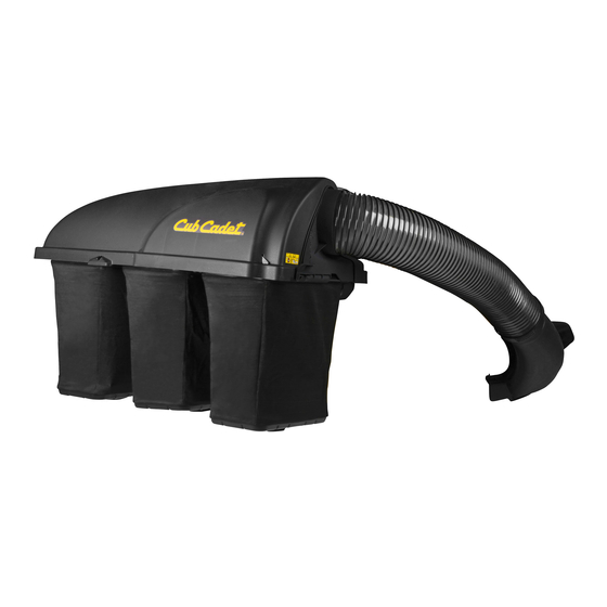
Triple Bagger Kit
Model OEM-190-192
IMPORTANT: Read safety rules and instructions carefully before operating equipment.
Warning:
This unit is equipped with an internal combustion engine and should not be used on or near any unimproved forest-
covered, brush-covered or grass-covered land unless the engine's exhaust system is equipped with a spark arrester meeting
applicable local or state laws (if any). If a spark arrester is used, it should be maintained in effective working order by the operator.
In the State of California the above is required by law (Section 4442 of the California Public Resources Code). Other states may have
similar laws. Federal laws apply on federal lands. A spark arrester for the muffler is available through your nearest engine authorized
service dealer or contact the service department, P.O. Box 361131 Cleveland, Ohio 44136-0019.
MTD LLC, P.O. BOX 361131 CLEVELAND, OHIO 44136-0019
FORM NO. 769-01137.fm
PRINTED IN U.S.A.
(2/2004)
Advertisement

Summary of Contents for MTD OEM-190-192
- Page 1 Federal laws apply on federal lands. A spark arrester for the muffler is available through your nearest engine authorized service dealer or contact the service department, P.O. Box 361131 Cleveland, Ohio 44136-0019. MTD LLC, P.O. BOX 361131 CLEVELAND, OHIO 44136-0019 FORM NO. 769-01137.fm PRINTED IN U.S.A.
- Page 2 TABLE OF CONTENTS Content Page Customer Support Important Safe Operation Practices Assembly & Operation Illustrated Parts List Warranty Back Cover FINDING MODEL NUMBER This Operator’s Manual is an important part of your new Triple Bagger Accessory. It will help you assemble, prepare and maintain the unit for best performance.
- Page 3 SECTION 1: IMPORTANT SAFE OPERATION PRACTICES WARNING: This symbol points out important safety instructions which, if not followed, could endanger the personal safety and/or property of yourself and others. Read and follow all instructions in this manual before attempting to operate this machine. Failure to comply with these instructions may result in personal injury.
- Page 4 26. Use only accessories and attachments approved for this dump cart, lawn roller, etc.) on slopes greater than 5 machine by the machine manufacturer. Read, degrees. When going down hill, the extra weight tends to understand and follow all instructions provided with the push the tractor and may cause you to loose control.
- Page 5 or trailer bed with a plastic liner. Always place complete stop within approximately (5) five seconds after containers on the ground away from your vehicle operating the blade disengagement control. If the blades before filling. do not stop within the this time frame, your unit should be When practical, remove gas-powered equipment serviced professionally by an authorized dealer.
- Page 6 SECTION 2: LOOSE PARTS The grass catcher kit is shipped with following loose parts in the carton. Please remove all loose parts, including the hardware pack, from the carton before discarding it. Compare with Figure 1 to check that all parts were included. Note that the kit and the hardware pack contain extra items which are not used on your unit.
- Page 7 SECTION 3: ASSEMBLY & OPERATION NOTE: References to left, right , front and rear of the tractor are from the operator’s position, unless otherwise stated. • Before assembly, place the tractor on a firm, level surface, disengage the PTO, stop the tractor engine and set the parking brake.
- Page 8 • Place a block of wood between the center deck housing baffle and the cutting blade to act as a Lock Nut stabilizer. See Figure 5. Remove this • Use a 15/16" wrench to remove the hex flange nut chute stop that secures the blade to the spindle assembly.
- Page 9 • Insert the curved end of chute tube into the hole in the grass bag cover following Figure 8. Insert chute tube here Place short strap here Attaching the strap Place long strap here Discharge Chute Figure 9 Operation Figure 8 •...
- Page 10 SECTION 4: PARTS LIST FOR MODEL OEM-190 17 11 16 25 29 13 Components of Cover Assembly pn # 664-04018: Components of Bag Assembly pn # 864-0251:...
- Page 11 Model OEM-190 Ref. Part No. Description Ref. Part No. Description 742-04056 Blade (for 50” decks only) 17200A Catcher Support Bracket 742-0679 Blade (for 54” decks only) 17247 Tubing Adapter 783-0601 Catcher Support Bracket 631-0221 Chute Elbow 783-0673 Catcher Support Bracket RH 664-04018 Cover Assembly (includes ref.
- Page 12 MANUFACTURER’S LIMITED WARRANTY FOR: The limited warranty set forth below is given by MTD LLC with MTD LLC does not extend any warranty for products respect to new merchandise purchased and used in the sold or exported outside of the United States, its United States, its possessions and territories.


