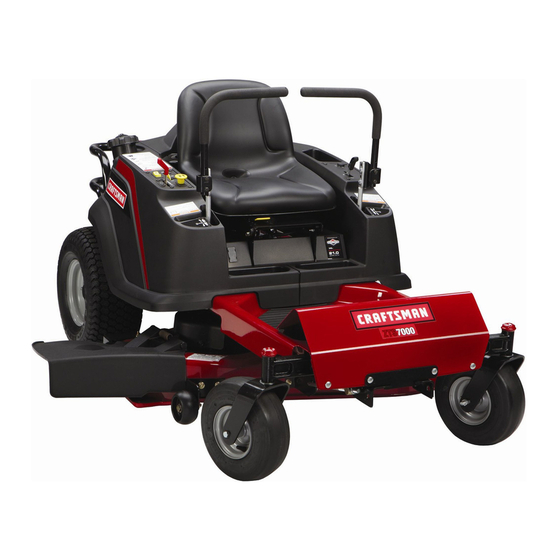
Craftsman ZT 7000 Operator's Manual
Zero-turn rear engine riders with electric start 20hp kohler with 44" mower 22hp briggs & stratton with 50" mower
Hide thumbs
Also See for ZT 7000:
- Operator's manual (100 pages) ,
- Operator's manual (27 pages) ,
- Operator's manual (117 pages)
Table of Contents
Advertisement
Available languages
Available languages
Operator's Manual
ZT 71
Zero-Turn Rear Engine Riders with Electric Start
Model No.
107.27772 (20HP Kohler with 44" Mower)
107.27774 (22HP Briggs
& Stratton
with 50" Mower)
CAUTION:
Before using this product, read
the manual and follow all its Safety Rules
and Operating
Instructions.
For answers to your questions
about this
product,
call:
1=800=659=5917
Sears Craftsman
Help Line
5 am - 5 pro, Mon - Sat
Nota: Una traducci6n
en espa6ol
de este Manual
del Operador
puede encontrarse
en la p&gina
35.
Sears, Roebuck and Co., Hoffman Estates, IL 60179
U.S.A.
Visit our Craftsman website: www.sears.com/craftsman
TP 199-4163-06-CZ-C
1727941
Revision 06
Advertisement
Table of Contents

Related Manuals for Craftsman ZT 7000


Summary of Contents for Craftsman ZT 7000
- Page 1 5 am - 5 pro, Mon - Sat Nota: Una traducci6n en espa6ol de este Manual del Operador puede encontrarse en la p&gina Sears, Roebuck and Co., Hoffman Estates, IL 60179 U.S.A. Visit our Craftsman website: www.sears.com/craftsman TP 199-4163-06-CZ-C 1727941 Revision 06...
- Page 2 For your convenience, iN HOME warranty service will still be available after the first 30 days of purchase, but a trip charge will apply. This charge will be waived if the Craftsman product is dropped off at an authorized Sears loca- tion.
- Page 3 Read thesesafetyrulesandfollow themclosely. Failure toobeytheserulescouldresult i n lossofcontrol of unit,severe personal injury or deathtoyou,or bystanders, or damage toproperty or equipment. This mowing deck is capable of amputating hands and feet and throwingobjects, ]'he triangle _ in text signifies important cautions or warnings which must be followed. GENERAL OPERATION 16.
- Page 4 SLOPE OPERATION WARNING Slopes are a major factor related to loss-of-control and tip- Never operate on slopes greater than 17.6 percent over accidents, which can result in severe injury or death. (10 °) which is a rise of 3-1/2 feet (106 cm) vertically in Operation on all slopes requires extra caution.
- Page 5 SERVICE AND MAINTENANCE Safe Handling of Gasoline 13. If the fuel tank must be drained, it should be drained 1. Extinguish all cigarettes, cigars, pipes, and other outdoors. sources of ignition. 2. Use only approved gasoline containers. 14. Replace faulty silencers/mufflers. 3.
- Page 6 SAFETY & OPERATION DECALS All DANGER, WARNING, CAUTION and instructional This unit has been designed and manufactured to pro- messages on your rider and mower should be carefully vide you with the safety and reliability you would expect read and obeyed. Personal bodily injury can result when from an industry leader in outdoor power equipment these instructions are not followed.
- Page 7 Tilt the seat forward to access the ID tag. Model Description Name/Number For answers to your questions about this product, call: 1-800-659-5917 Stock Number Unit Serial Number Sears Craftsman Help Line, 5 am - 5 pm, Monday-Saturday. Date Purchased Engine Make Engine Model Engine Type/Spec Engine Code/Serial...
- Page 8 • Two Bin Bagger • Headlight = Front Bumper Setup instructions - Setup instructions - Operator's Manual & Parts English Spanish Book - English/Spanish Setup Setup Troubleshooting Troubleshooting Keys...
- Page 9 Push Unit Off Crate Read The Operator's Manual To push the unit off the crate: Set BOTH transmission * Read the operator's manual. release levers to PUSH posi- You should always read and follow tion by pulling the levers back the instructions in the operator's (levers are located at the rear manual.
- Page 10 Right Ground Speed& ParkingBrake Lever N,-',(®) Throttle (Fast) Throttle ilow) Choke (Closed) l C,oke (Open) Cutting Height Adjust ReleaseLevers PTO(Mower) Transmission Switch ignition(Key) Ground Speed Levers- Ground Speed Levers- Switch DRIVE Pesitons PARK Pesitoes Figure 1. Controls CONTROL FUNCTIONS The information below briefly describes the function of individual controls. Starting, stopping, driving, and mowing require the combined use of several controls applied in specific sequences.
- Page 11 _PTO Switch Mower Height of Cut Adjustment To adjust cutting height, rotate the turn crank clockwise The PTO (Power Take-Off) switch engages and disen- to raise the mower deck and counterclockwise to lower gages the mower deck. To turn the mower on, pull the the mower deck.
- Page 12 CHECKS BEFORE STARTING • Check that the crankcase oil is filled to full mark on dipstick. Fill the fuel tank with fresh fuel. FUEL RECOMMENDATIONS For daily operation: Use only unleaded gasoline with a pump sticker octane rating of 87 or higher. Gasohol (up to 10% ethyl alcohol, 90% unleaded gasoline by volume) is approved as a fuel.
- Page 13 EMERGENCYSTOPPING 7. Begin mowing. See DRIVING PRACTICE. 8. When finished, turn the PTO switch OFE In the event of an emergency the engine can be stopped by simply turning the ignition switch to STOR Use this 9. Stop the engine (see STOPPING THE RIDER AND method only in emergency situations.
- Page 14 DRiViNG PRACTICE Smooth Travel The lever controls of the BASIC DRIVING zero turn rider are WARNING: Never operate on slopes greater than 17.6% highly responsive. (10°). See SLOPE OPERATION in the safety section. The BEST method of Zero turn riders operate differently from other four- handling the ground wheeled vehicles.
- Page 15 PracticeTurning Around a Corner PracticeTurning In Place While traveling forward allow one handle to gradually To "zero turn" means to turn in place. To turn in place, return back toward neutral. Practice several times before gradually move one ground speed control lever forward from neutral and one lever back from neutral simultane- mowing.
-
Page 16: Mower Deck Removal & Installation
MOWER DECK REMOVAL & INSTALLATION NOTE: Perform mower removal and installation on a hard, level surface such as a concrete floor. WARNING Engage parking brake, disengage PTO, stop engine and remove key before attempting install or remove the mower. Removing Mower Deck 1. - Page 17 MAINTENANCE SCHEDULE The following schedules should be followed for normal care of your rider and mower. RNDER MAINTENANCE, All Models Before Spring Yearly Each Use & Fall Hours Hours Hours Hours Clean Debris from Rider and Engine Compartment * • Clean Debris from Engine Cooling Areas &...
- Page 18 Rider Maintenance items CLEAN DEBRIS FROM RIDER AND ENGINE COMPARTMENT Service interval: Before each use. CAUTION: if debris is not removed from the engine compartment and other hot surfaces, it creates a fire hazard. Before starting the unit at the beginning of the mowing session, remove any grass clippings, dirt, leaves, or other debris from the unit.
- Page 19 LUBRiCATiON Service Interval: 25 hours. Lubricate the unit at the locations shown in Figures 15 through 17 as well as the following lubrication points. Grease: front wheel bushings • mower pivots • front wheel grease fittings mower arbors Use grease fittings when present. Not all greases are compatible.
- Page 20 CLEAN DECK & CHECK / REPLACE MOWER BLADES Service Interval: 25 hours or as required. WARNING For your personal safety, do not handle the sharp mower blades with bare hands. Careless or improper handling of blades may result in serious injury.
- Page 21 CLEANING THE BATTERY AND CABLES CHECK RIDER SAFETY , WARNING SYSTEM Be careful when handling the battery. Avoid Service interval: Every 100 hours, every spring/fall, spilling electrolyte. Keep flames and sparks away and after storage of 30 days or longer. from the battery.
- Page 22 CHECK / ADJUST PTO CLUTCH WARNING To avoid serious injury, perform adjustments only with engine stopped, key removed and tractor on level ground. Service Interval: 200 Hours. The PTO clutch is engaged and disengaged by the PTO switch. The clutch powers and brakes the mower blades. Check the PTO clutch adjustment every 200 hours of operation.
- Page 23 Engine Maintenance Items Use 0il classified API Service ClassSG, SH, SJ or better with SAE Viscosity: CHECK ENGINE OIL LEVEL - E Ej, KOHLER MODELS Service interval: Before each use, and every 8 hours. 1. Turn the engine off, and set the ground speed con- trois to PARK.
- Page 24 REPLACE AIR FILTER - KOHLER MODELS Service Interval: Every 25 hours or two months, or as required. 1. Loosen the air filter cover knobs (A, Figure 2G) and remove the cover (B). Clean out any debris from around the air filter. Inspect the condition of the seal- ing surfaces of the air filter element (C) and filter base (D).
- Page 25 CHECK ENGINE OIL LEVEL - Useoil classifiedAPIService Class SF, BRIGGS & STRATTON MODELS SG, SH, SJ or betterwith SAEViscosity: Service interval: Before each use, and every 8 hours. 1. Turn the engine off, and set the parking brake to PARK. 2.
- Page 26 AiR FILTER & PRE-CLEANER SERVICE - BRIGGS & STRATTON MODELS Service Interval: Pre-Cleaner: Every 25 hours or as required. Air Filter: Every 50 hours or as required. Replacement Interval: Pre_Cleaner: As required. Filter: Every 200 hours or once per season. Air Filter Removal &...
- Page 27 REPLACE SPARK PLUG - BRIGGS & STRATTON MODELS Service interval: Yearly Replacement Spark Plug: 71/500/691043 Spark Plug Gap: .030" (.76mm) 1. Stop the engine and allow it to cool. 2. Clean the area around the spark plug. 3. Remove the spark plug. 4.
- Page 28 GROUND SPEED CONTROL LEVER ADJUSTMENT The control levers have three adjustments: To Adjust Control Lever Height: Pull the levers in across the operator's lap to their DRIVE positions. Loosen the mount bolts (D, Figure 34) and raise or lower the levers to the desired position. Tighten the mounting bolts.(D).
- Page 29 CUTTING HEIGHT ADJUSTMENT Turn the cutting height adjustment crank (A, Figure 35) clockwise to raise the mower deck and counterclockwise to lower it. If the crank is difficult to turn, thoroughly clean and lubricate it. PTO CLUTCH ADJUSTMENT See CHECK / ADJUST PTO CLUTCH in the Maintenance Section.
- Page 30 MOWER DECK LEVELING ADJUSTMENTS WARNING Before checking mower, shut off PTO and engine. Allow all moving parts to stop. Remove ignition key, then disconnect the spark plug wire and fasten it away from the spark plug. Side to Side Leveling Figure 37.
- Page 31 Max 1/4 Turn Max 1/4 Turn Starting Position to Lower the to Raise the Front of the Front of the Mower Mower Figure 36. Orient Blades Front-to=Back Front To Back Leveling If the cut is uneven, the mower may need leveling. Unequal or improper tire pressure may also cause an uneven cut.
- Page 32 STORAGE WARNING Before you store your unit for the off-season, read the Never store the unit (with fuel) in an enclosed, Maintenance and Storage instructions in the Safety poorly ventilated structure. Fuel vapors can Rules section, then perform the following steps: travel to an ignition source (such as a furnace, •...
- Page 33 While normal care and regular maintenance will extend the life 4 ]LWARNING of your equipment, prolonged or constant use may eventually require that service be performed to allow it to continue operat- To avoid serious injury, perform maintenance ing properly. The troubleshooting guide below lists the most the rider or mower only when the engine is common problems, their causes and remedies.
- Page 34 Transmission release levers in PUSH Engine runs, but Move levers to DRIVE positions. rider will not aositions. drive. Drive belt slips. Clean or replace belt as necessary. Belt is broken. Replace drive belt. Contact Sears Parts & Repair. Parking brake is not fully released. Contact Sears Parts &...
- Page 35 Antes que 1=800-659-5917 arranque el motor, lea y comprenda Manual del DueBo. Servicio de ayuda Sears Craftsman 5 am - 5 pm, Lunes a Sabado...
- Page 36 CILIO seguir_ estando disponible despu_s de los primeros 30 dias de compra, pero habrdt un cargo per el recorrido. Este cargo quedar_t anulado si se Ileva el producto Craftsman en uno de los lugares autorizados de Sears. Para averiguar cuAI es el Sears m#ts cercano a usted, le rogamos que Ilame a 1-800-MY-HOME.
- Page 37 Leaestasreglas deseguridad y sfgalas concuidado. Noobedecer e stas re@as p uedeocasionar la perdida delcontrol s obrela unidad, l esiones s everas a la persona o la muerte deusted, o espectadores, o daOos a la )iedad o al equipo. Esta cubierta de la podadora es capaz de amputar manos ypies y de arrojar _etos.
- Page 38 OPERACION EN CUESTAS ADVERTENOIA Las cuestas son un factor importante relacionado con los acci- dentes por perdida de control y volcaduras, y pueden propiciar Nunca opere en cuestas mayores a 17.6 per ciento lesiones severas o la muerte. Cualquier operacion en cuestas (10 °) Io cual es una inclinaciOn de 3 1/2 pies (106 cm) exige precauciones extremas.
- Page 39 SERVIClO Y MANTENIMIENTO 10. Mantenga o reemplace las etiquetas de seguridad y de instrucciones seglJn sea necesario. Manejo Seguro de la Gasolina 11. No quite el filtro de la gasolina cuando el motor esta 1. Apague cigarros, puros, pipas y otras fuentes de ignici6n. caliente ya que la gasolina que se derrame se puede incen- 2.
- Page 40 CALCOMANJAS DE SEGURiDAD OPERACION Debe leer cuidadosamente y acatar todos los mensajes de PELIGRO, ADVERTENCIA, PRECAUCION y de instrucciones Esta unidad fue disehada y fabricada para ofrecerle la seguridad en su tractor y podadora. No seguir las instrucciones puede y confiabilidad que usted esperaria de un lider en la indus- resultar en lesiones personales al cuerpo, iLa informaci6n es...
- Page 41 Para obtener respuestas a sus preguntas sobre el pro- ducto, Ilame ah 1-800-659-5917 Fecha de Compra Servicio Telef6nico de Asistencia de Sears Craftsman, 5 am- 5 pro, Lunes- S&bado. Ma[ca de[ Moto_ Modelo del Motor...
- Page 42 * Recolector de Hierba con Bolsa Gemela * Faro delantero Instrucciones Instrucciones Manual dei Operador y Libro de Disposici6n - Ingl_s Disposicibn - EspaSol Partes - Ingles/EspaSol Setup Setup z_ _o0o i_!:;-7;; ..... Troubleshooting Troubleshooting Llaves...
- Page 43 Leer el Manual dei Saque la unidad de la Operador caja Para sacar la unidad de la caja: Usted siempre debe leer y seguir las instrucciones en el manual del , Ajuste AMBAS palancas de desen- Operador. En este importante docu- ganche de la transmisi6n en posici6n mento encuentra informaci6n sobre PUSH colocando ]as palancas hacia atras (las palan-...
- Page 44 "_ Palanca de Palanca de Velocidad Izquierda Velocidad Derecha & & Freno de Mano FreRo de Mano Aoelerador (Rapido o con Gas) Acelerador (Lento o Inactivo) Ahogador (Cerrado) Tanque de Ahogador (Abierto) Gasolina Ajuste de Altura de Corte . _" Palancas de D_emb,_gue ,n_p_o_ de...
- Page 45 Interruptor Ajuste de AItura de Corte de Podadora Para ajustar la altura de corte, gire la manivela a la El interruptor PTO (Eliminador de Energfa) embraga y derecha para subir la cubierta de la podadora y a la desembraga un embrague electrico conectado al izquierda para bajar la cubierta de la podadora.
- Page 46 VERIFICACIONES ANTES DE ARRANCAR - Verifique que el aceite del carter este en la marca de Ileno de la varilla de nivel de aceite. - Llene el tanque de gasolina con combustible fresco. RECOMENDACIONES DE COMBUSTIBLE Para operaci6n diaria: Use s61o gasolina sin plomo donde la calcomania de la bomba indique un octanaje de 87 o mayor.
- Page 47 PARO DE EIVIERGENCIA 7. Comience a cortar el cesped. Refierase a PRACTICA DE MANEJO. En el caso de una emergencia, el motor puede detenerse simple- 8. AI terminar, coloque el interruptor PTO en la posicion OFF mente girando el interruptor de encendido a STOR Use este (apagado).
- Page 48 PRACTICA DE MANEJO Traslado sin prob- lemas MANEJO B,4S#CO Los controles de palanca ADVERTENCIA: Nunca opere en cuestas mayoras a 17.6% del tractor de giro cero son (10°), Vea OPERACION EN CUESTAS en la seccion de altamente sensibles. seguridad. Los tractores de giro cero operan de modo difer- El MEJOR metodo de ente a otros vehfculos de cuatro ruedas.
- Page 49 Pr_ctica de dar Vuelta en una Esquina Pr_ctica de Vuelta en el Lugar Mientras viaja hacia adelante permita que una palanca Hacer un "giro cero" significa girar en el misme lugar. regrese gradualmente en direcci6n del neutral. Practique Para dar la vuelta en el mismo lugar, gradualmente varias veces antes de podar el cesped.
- Page 50 REIVIOCION E INSTALACION DE LA CUBIERTA DE LA PODADORA NOTA: Ejecute la remocidn e instalacidn de la podadora sobre una superflcie dura y nivelada como un piso de concreto. ADVERTENCIA Accione el freno de mano, desacople el PTO, detenga el motor y quite la Ilave antes de intentar instalar o quitar la podadora.
- Page 51 PROGRAMA DE IVIANTENIMIENTO El siguiente programa debe seguirse para el cuidado normal de su tractor y podadora. _ANTENIMIENTO DEL MONTABLE, de todos los Antes de Primavera y 8 Anual rnodeloe cada ueo Verano aoras Horas Horas Horas mente _impie el residuo del montable y del compartimiento Jel motor * _impie el residuo de las areas de refrigeraci6n del +notor y del filtro de aire *...
- Page 52 Elementos de lVlantenimiento del Tractor MMPIAR DESPOJOS DEL TRACTOR Y DEL COMPARTIMIENTO DEL MOTOR Intervalo de Servicio: Antes de cada use. PRECAUCION: Si no se quitan los despojos del com- partimiento dei motor y otras superficies calientes, se crea un peligro de incendio. Antes de arrancar la unidad al inicie de la sesi6n de pedade de c_sped, elim- ine cualquier hierba cortada, mugre, hojas u otros...
- Page 53 LUBRICACION Intervalo de Servicio: 25 horas. Lubrique la unidad en los lugares mostrados en las Figuras 15 a 17 asf como en los siguientes puntos de lubricaci6n. Grasa: engrasadores de la rueda delantera bujes de la rueda delantera pivotes de la podadora •...
- Page 54 LIMPIAR CUBIERTA Y VERIFICAR/ REEIVIPLAZAR ASPAS DE PODADORA Intervalo de Servicio: 25 horas o segun se requiera. AOVERTENCIA Para su seguridad personal, no maneje lae aspas afiladas de la podadora con las manos deacubiertas. El manejo imprudente o indebido Afloje de las aspas puede resultar en lesiones graves.
- Page 55 LIMPIAR BATERJA Y CABLES ADVERTENCIA VER[FICAR SISTEMA SEGURIDAD DEL TRACTOR Tenga cuidado al manejar la bateria. Evite derramar el electrolito. Mantenga llamas y Intervalo de Servicio: 200 Horas y Cada Primavera y Otofio chispas lejos de la bateria. Cuando quite o instale Esta unidad esta equipada con interruptores de intercierre de los cables de la bateria, desconecte PRIMERO el seguridad.
- Page 56 VERIFICAR/AJUSTAR EMBRAGUE DEL PTO - IL ADVERTENCIA Para evitar lesiones graves, sAIo haga los ajustes con el motor detenido, la nave quitada y el tractor en terreno nivelado, Intervalo de Servicio: 200 horas. El embrague del PTO se embraga y desembraga con el interruptor PTO.
- Page 57 Elernentos de Mantenimiento Use aceite de Servicio clasificado para API de Clase SG, SH, SJ o mejor con viscosidad SAE. del Motor l_wEtll> VERIFIQUE EL NIVEL DE ACEITE 4t[]!1 MOTOR - EN MODELOS KOHLER Service Interval: Before each use, and every 8 hours. ,,Bsm 1.
- Page 58 REEMPLACE EL FILTRO DE AIRE - MODELOS KOHLER Intervalo de servicio: Cada 25 horas o cada dos meses, o conforme sea necesario. 1. Afloje los botones de la cubierta del filtro de aire (A, Figura 26) y remueva la cubierta (B). Limpie cualquier residue alrededor del filtro de aire.
- Page 59 VERIFIQUE EL NIVEL DE ACEITE DEL Use aceite de Servicio clasificado para API de MOTOR - MODELOS BRIGGS & STRATTON Clase SG, SH, SJ o major con viscosidad SAE. Intervalo de servicio: Antes de cada uso, y cada 8 horas. 1, Apague el motor, y coloque el freno de parada en la posicion de PARK (parado).
- Page 60 SERVlCIO DEL FILTRO DE AIRE Y DEL PRE- PURIFICADOR - MODELOS BRIGGS & STRATTON Intervalo de servicio: Prepurificador: cada 25 horas o conforme sea necesario. Filtro de aire: cada 50 horas o conforme sea necesario. Intervalo de reemplazo: Prepurificador: conforme sea necesado.
- Page 61 REEMPLACE LA BUJ|A DE ENCENDIDO MODELOS BRIGGS & STRATTON Intervalo de servicio: Anualmente Bujia de encendido de reposici6n: 71/500/691043 Separaci6n de la bujia de encendido: .030" (.76mm) 1. Pare el motor y espere a que se enfrie. 2. Limpie el Area alrededor de la bujfa de encendido. 3.
- Page 62 AJUSTE DE PALANCA DE CONTROL DE VELOClDAD Las palancas de control tienen tres ajustes: Para Aiustar la AItura de las Palancas de Control: Jale las palancas hacia adentro, encima del regazo del operador a la posici6n de DRIVE. Afloje los pernos de montaje (D, Figura 34) y suba o baje las palancas a la posici6n deseada.
- Page 63 AJUSTE DE LA ALTURA DE CORTE Gire la manivela del ajuste de la altura de corte (A, Figura 35) a la derecha para subir la cubierta de la podadora y a la izquierda para bajarla. Si se le dificulta girar la manivela, limpiela bien y lubriquela.
- Page 64 AJUSTE DE NIVEL DE LA CUBIERTA DE LA PODADORA ADVERTENClA Antes de verificar la podadora, apague el PTO y el motor. Permits que se detengan todas las partes en movimiento. Quite la Ilave del eneendido, luego desconecte el cable de la bujia y suj_telo lejos de la bujia.
- Page 65 Figura40, Orientar las Aspas de Adelante hacia Atr;_s Nivelado de Adelante hacia Atr&s 1. Gire las aspas de adelante hacia atras como se muestra en la Figura 40. Mida la distancia del suelo a la punta delantera del aspa central, y del suelo a la punta trasera de las aspas izquierda y derecha (Figura 40).
- Page 66 ALMACENAMIENTO ADVERTENCIA Antes de almacenar su unidad en la temporada baja, lea las Nunca almacene la unidad (con combustible) en una instrucciones de Mantenimiento y Almacenamiento en la sec- eetructura cerrada con poca ventilaei6e. Los vaporee ci6n de Reglas de Seguridad, luego realice los siguientes del combustible pueden viajar a una tuente de ignicibe...
- Page 67 ADVE RTENCIA s, Io prefiere, tedoa estos procedimientos pueden ser ejecutados para usted per un Para evitar lesionea graves, realice el mantenimiento del tractor o la Centre de Partes y Reparaciones podadora sblo con el motor apagado y el freno de mane en PARK. Sears.
- Page 68 El motor opera Las palancas de desembrague de la Mueva las palancas a la posici6n de DRIVE. pero el tractor transmisi6n en posici6n do EMPUJAR. nO avanza, La banda de tracci6n se barre. Limpie o roemplace la banda segQn sea necesario. La banda esta rota.
- Page 69 RepairParts PTS - 1...
- Page 70 Frame, Body & Seat Group ZT 7000 107.27772 & 107.27774 NOTE: Unless noted otherwise, use the standard hardware torque specification chart. Right Rear Kohier Engine 17 61-- OnJy. _'34 Torque Capscrew to 72-77 ft, Ibs. or 97.6-104.4 Nm &_. "41 PTS - 2...
- Page 71 Frame, Body & Seat Group ZT7000-107.27772 & 107.27774 REF NO PART NO. QTY. DESCRIPTION 1726018SM SEAT ASSEMBLY, wth Arm Rests (Includes Ref. No, 68) 1687021SM ARM REST KIT, (L.H. & R.H.) 1727332ASM SUPPORT, Seat 1960694SM NUT, Hex Flange ESNA, 1/4-20 1931648SM CAPSCREW, Hex Head Whiz Lock Dog Point, 5/16-18 x 3/4...
- Page 72 Frame, Body & Seat Group ZT 7000 107.27772 & 107.27774 NOTE: Unless noted otherwise, use the standard hardware torque specification chart. Right Rear Kohier Engine 17 61-- OnJy. _'34 Torque Capscrew to 72-77 ft, Ibs. or 97.6-104.4 Nm &_. "41 PTS - 4...
- Page 73 Frame, Body & Seat Group ZT 7000 107.27772 & 107.27774 REF NO PART NO. QTY. DESCRIPTION 1664847SM SCREW, Hex Washer Head Taptite, 5/16-18 x 3/4 1726024ASM BRACKET, Footrest Support 1960368SM NUT, Speed Lug Type, 1/4-20 1930641SM NUT, Hex Flange Whiz Lock, 1/4-20 1930644SM NUT, Hex Flange Two-Way Lock, 1/2-13 1709235SM...
- Page 74 Engine Group - 20HP Kohler ZT 7000 - 107.27772 & 107.27774 NOTE: Unless noted otherwise, use the standard hardware torque specification chart. Apply end of foam under seat deck support and to miss plastic air filter cover and rotatiing screen, Tie both throttle and clutch cables to seat support support...
- Page 75 Engine Group - 20HP Kohler ZT7000-107.27772 & 107.27774 REF NO PART NO, QTY, DESCRIPTION ENGINE, 20HP, KOHLER Courage, Model #SV600S, Type # 0010 1727809SM MUFFLER 1728982SM SHIELD & INSULATION ASSEMBLY, Muffler, Heat Top 1727937ASM SHIELD, Muffler, Heat Side 1924856SM CAPSCREW, Hex Head, 5/16-18 x 1/2, G5 1930595SM CAPSCREW,...
- Page 76 Engine Group - 22HP Briggs & Stratton ZT 7000 107.27772 & 107.27774 NOTE: Unless noted otherwise, use the standard hardware torque specification chart. support and to miss plastic air filter ._. ,_!Apply end of foam under seat deck cover and rotatiing screen, NOTE: Torque the tour engine mounting bolts...
- Page 77 Engine Group - 22HP Briggs & Stratton ZT 7000 - 107.27772 & 107.27774 REF NO PART NO, QTY, DESCRIPTION ENGINE, 22HP, Briggs & Stratton, Model # 442777, Type # 0120-E1 1727805SM MUFFLER 1727939ASM SHIELD, Heat, Muffler Side 1727938ASM SHIELD, Heat, Muffler Top 1728017ASM SHIELD, Heat, Throttle 1960295SM...
- Page 78 Carrier & Transmission Group ZT 7000 107.27772 & 107.27774 NOTE: Unless noted otherwise, use the standard hardware torque specification chart. 90 degree elbow from cel_ter _ine Torque to /_t 160- 210 in Ibs 90 degree elbow be adiusted 65 5" ± 3 f_om oer_ter lirle ./13 i "_...
- Page 79 Carrier & Transmission Group ZT 7000 107.27772 & 107.27774 REFNO PARTNO. QTY. DESCRIPTION 1960251SM NUT, Hex Centerlock Jam, 3/8-16 1960666SM NUT, Hex Flange, 5/16-18 ESNA 1960236SM SPACER 1960223SM CARRIAGE BOLT, 5/16-16 x 1, G5 1727555SM ROD, Control, L.H. 1919381SM WASHER, 5/16 1728060SM HYDRO SEAL KIT 1727831SM...
- Page 80 Carrier & Transmission Group ZT 7000 107.27772 & 107.27774 NOTE: Unless noted otherwise, use the standard hardware torque specification chart. 90 degree elbow from cel_ter _ine Torque to /_t 160- 210 in Ibs 90 degree elbow be adiusted 65 5" ± 3 f_om oer_ter lirle i "_ ".
- Page 81 Carrier & Transmission Group ZT 7000 107.27772 & 107.27774 REF NO PART NO. QTY. DESCRIPTION 5020601SM NUT, Hex, 1/2-20 1960734SM NUT, Hex Centerlock Jam, 7/16-14 1928352SM NUT, Hex Flange, 3/8-16, Whiz Lock 1717024SM CLIP, Rod End Clevis R.H, 1930633SM NUT, Hex Head Center Lock 1728073SM PULLEY, 4,5", Transmission 1728074SM...
- Page 82 Controls Group ZT 7000 - 107.27772 & 107.27774 NOTE: Unless noted otherwise, use the standard hardware torque specification chart. Handlebarsout (locked) compress 6 _12 Ibs inward force measured brakespring to 3" length 1. / t" above bottom of foam gripe (both sides).
- Page 83 Controls Group ZT7000-107.27772 & 107.27774 REFNO PARTNO. QTY. DESCRIPTION 1725927SM SHAFT, Cross 1960027SM WASHER, 1/2 1703805SM RING, Klipring Extension 1921977SM CAPSCREW, Hex Head, 5/16-18 x 1-1/4, G5 1920161SM NUT, Hex Jam, 5/16-18 1960717SM NUT, Speed, 5/16-18 Lug Type 1960686SM NUT, Hex Flange, 5/16-18 ESNA 172800gASM BRACKET, L.H.
- Page 84 Controls Group ZT 7000 - 107.27772 & 107.27774 NOTE: Unless noted otherwise, use the standard hardware torque specification chart. Handlebarsout (locked) compress 6 _12 Ibs inward force measured brakespring to 3" length 1. / t" above bottom of foam gripe (both sides).
- Page 85 Controls Group ZT7000-107.27772 & 107.27774 REF NO PART NO, QTY. DESCRIPTION 1960694SM NUT, Hex Flange, 1/4-20 ESNA 1925003SM SCREW, Hex Washer Head Taptite, 1/4-20 x 1/2 Footnotes PTS-17...
- Page 86 Electrical Group ZT 7000 - 107.27772 & 107.27774 NOTE: Unless noted otherwise, use the standard hardware torque specification chart. Sent Swllch 5 .--__ Tieswitchlocabte 11 connector bogy ',/\ TOStarter8nit on Engine Tie Harness Headlight (Optional) Electric CInlch TOEngine PTS - 18...
- Page 87 Electrical Group ZT7000-107.27772 & 107.27774 REFNO PARTNO. QTY. DESCRIPTION 1732006SM SWITCH, Push Button 1686734SM SWITCH ASSEMBLY, Ignition (includes Ref. Nos. 3, 4, 5 & 6) 1960547SM LOCKWASHER, Internal Tooth, Ignition Switch 1717549SM NUT, Hex Flange, 5/8-32, Ignition Switch 1717550SM COVER, Ignition Switch 1717163SM KEYS (Set of Two Keys) 1731185SM...
- Page 88 Wheels & Tires Group ZT 7000 107.27772 & 107.27774 NOTE: Unless noted otherwise, use the standard hardware torque specification chart. PTS-20...
- Page 89 Wheels & Tires Group ZT7000-107.27772 & 107.27774 QTY. DESCRIPTION REFNO PARTNO, 2860202SM WASHER, 3/4 2830647SM NUT, Hex Lock PAL, 3/4-20 1722675SM CAP, Hub 1726383SM WHEEL & TIRE ASSEMBLY, Rear 2172353SM VALVE STEM & CAP 5020601SM NUT, Hex Lug, 1/2-20 1726382SM WHEEL &...
- Page 90 Decals Group ZT 7000 - 107.27772 & 107.27774 NOTE: Unless noted otherwise, use the standard hardware torque specification chart. REARVIEW PTS-22...
- Page 91 DECAL Do Not Remove Foam Seal 1728045SM DECAL Seat Deck Stripe, L,H. 1727858SM DECAL ZT 7000 (2044) 1727857SM DECAL ZT 7000 (2250) 1728049SM DECAL. CRAFTSMAN 1727855SM DECAL Panel Upper, Operation 1727856SM DECAL Panel Lower, Warning/Danger & Icon Indicator 1726638SM DECAL Tracking...
- Page 92 44" & 50" Mower Deck - Clutch & Support Group ZT 7000 107.27772 & 107.27774 NOTE: Unless noted otherwise, use the standard hardware torque specification chart. PTS - 24...
- Page 93 44" & 50" Mower Deck - Clutch & Support Group ZT 7000 - 107.27772 & 107.27774 REF NO PART NO. QTY. DESCRIPTION 1727869SM V-BELT, 44 '_Mower Deck 1726472SM V-BELT, Mower Drive, 50" Mower Deck 1727773SM V-BELT, P.T.O. 44" Mower Deck 1726471SM V-BELT, P.T.O.
- Page 94 44" & 50" Mower Deck - Height Adjustment Group ZT 7000 107.27772 & 107.27774 NOTE: Unless noted otherwise, use the standard hardware torque specification chart. PTS - 26...
- Page 95 44" & 50" Mower Deck - Height Adjustment Group ZT 7000 - 107.27772 & 107.27774 REF NO PART NO. QTY. DESCRIPTION 1931202SM CAPSCREW, Hex Washer Head Taptite, 5/16-18 x 1-1/4 1919381SM WASHER, 5/16 1704114SM ROD, Indicator Height of Cut 1726424ASM PLATE &...
- Page 96 44" & 50" Mower Deck - Height Adjustment Group ZT 7000 107.27772 & 107.27774 NOTE: Unless noted otherwise, use the standard hardware torque specification chart. PTS - 28...
- Page 97 44" & 50" Mower Deck - Height Adjustment Group ZT7000-107.27772 & 107.27774 REF NO PART NO. QTY. DESCRIPTION 1709195SM SPACER 1611705SM SPACER Footnotes PTS-29...
- Page 98 44" & 50" Mower Deck - Housing & Arbor Group ZT 7000 107.27772 & 107.27774 NOTE: Unless noted otherwise, use the standard hardware torque specification chart. Torque Nuts (3) to 55-75 Ft. Lbs. Torque Oapscrews to 45-55 Ft Lbs. or 61-75 NM PTS-30...
- Page 99 44" & 50" Mower Deck - Housing & Arbor Group ZT 7000 - 107.27772 & 107.27774 REF NO PART NO. QTY. DESCRIPTION 171441gSM NUT, Hex Flange Non-Locking_ g/16-18 1713675SM WASHER, Belleville 1720387SM PULLEY 1713158SM HUB, Spacer, 2-13/32 1713098SM PULLEY 1713533SM HUB 35/64 1713197SM Serrated, 35/64...
- Page 100 44" & 50" Mower Deck - Housing & Arbor Group ZT 7000 107.27772 & 107.27774 NOTE: Unless noted otherwise, use the standard hardware torque specification chart. Torque Nuts (3) to 55-75 Ft. Lbs. Torque Oapscrews to 45-55 Ft Lbs. or 61-75 NM PTS-32...
- Page 101 44" & 50" Mower Deck - Housing & Arbor Group ZT7000-107.27772 & 107.27774 REF NO PART NO, QTY, DESCRIPTION 1920397SM NUT, 1/4-20 ESNA Footnotes PTS-33...
- Page 102 Kohler Engine Parts ZT 7000 - Model No. 107.27772 Oil Pan / Lubrication - Group 3 Crankcase - Group 2 13\9 PTS-34...
- Page 103 Kohler Engine Parts ZT 7000 - Model No. 107.27774 RE}:. PART DESCRiPTiON REF. PART DESCRIPTION SPECIAL PARTS HEAD/VALVE/BREATHER - Group 4 20 622 01 Short Block 20 096 07-S Kit, valve cover (Includes 2) 20 766 05-3 Gasket Set 20 041 13-S Gasket, valve cover M-646020-S Screw, hex.
- Page 104 Kohler Engine Parts ZT 7000 - Model No. 107.27772 Blower Housing & Baffles - Group 6 Ignition / Electrical - Group 5 3_-Q l_f @ Starting System - Group 7 _Fuel System - Group 8_ PTS - 36...
- Page 105 Kohler Engine Parts ZT 7000 - Model No. 107.27774 RE}:. PART DESCRiPTiON REF. PART DESCRiPTiON IGNmON!ELECTRICAL - Group 5 20 162 02-S Screen, grass 12 086 14-S Screw, hex. flange M10x1.Sx46 12 468 03-S Washer, spring 3/16" 20 146 02-S Plate, fan mounting 20 15701-S X-42-15-S...
- Page 106 Kohler Engine Parts ZT 7000 - Model No. 107.27772 Exhaust-Group11 Air Intake / Filtration - Group 10 Exhaust Controls - Group 9 PTS-38...
- Page 107 Kohler Engine Parts ZT 7000 - Model No. 107.27774 REF. PART DESCRiPTiON REF. PART DESCRiPTiON ENGINE CONTROLS =Group 9 20 536 03-3 Control assembly, speed 12 237 01-S Clamp, cable 24 086 43-S Screw, torx hd. ctsk. M5x0.8x16 M-664020-S Screw, lobed sckt. M6xl.0x20 20 079 05-S Linkage, choke- single wire...
- Page 108 Briggs & Stratton Engine Parts zT 7000 Model No. 107.27774 1330 REPAIR IVlANUA_. 929A _' 213_ 267_ 188 _ 265 [_ [1330 REPAIR IVlANUA_. 267 _, PTS - 40...
- Page 109 Briggs & Stratton Engine Parts ZT 7000 Model No. 107.27774. 1022 1029 1029 1100 798 % _11oo • _ 914% _o_o_ 240 _ 333_ 1169 142J_ 628 _' 413_ 9_.8 1128_ 385 _ F??!],231o72_ 387':_ 121 CARBURETOR OVERHAUL 913 0 _130 o16_ 104_51_...
- Page 110 Briggs & Stratton Engine Parts ZT 7000 Model No. 107.27774 741t 1095 VALVE GASKET 1022 789A 358 ENGINE GASKET 3© 20 _ 276 ® 943 Q 691 Q 1022 PTS - 42...
- Page 111 Briggs & Stratton Engine Parts ZT 7000 Model No. 107.27774 PART NOTES DESCRIPTION PART NOTES DESCRIPTION 899742 Cylinder Assembly 693148 Nut (Ring Gear) 499585 Kit-Bushing/Seal (Magneto 698742 Line-Fuel (Cut to Required Side) Length) 391086 187A 699883 Line-Fuel (Molded) Seal-Oil (Magneto Side) 699747 Sump-Engine 691108...
- Page 112 Briggs & Stratton Engine Parts ZT 7000 Model No. 107.27774 FIEF. PART NOTES DESCRIPTION REF. PART NOTES DESCRIPTION 697891 1051 691265 SeaI-O Ring (Intake Manifold) Ring-Retaining 691108 1054 280275 Cable-Tie Screw (Fuel Pump Bracket) 1058 275475 Owner's Manual 690998 Seal-Choke/Throttle Shaft 66536 1090...
- Page 113 HardwaregdefitificatiaH Terqu8 SpBcificatigfis Common Hardware Types Torque Specification Chart HexHead Capscrew FORSTANDARD MACHINEHARDWARE (Tolerance _*20%) (_Washer © © Lockwasher Hardware Grade CarriageBolt SAE Grade 2 SAE Grade 5 8AEGrade 8 HexNut Size Of in//bs in/Ibs in_b_ Hardware ft]]bs flJ]bs Wlbs Standard Hardware Sizing 8-32 When a washer or nut is identified...
- Page 114 PTS-...
- Page 115 Feticidades por su compra inteligente. Su nuevo produc- Craftsman® product is designed and manufactured for to de Craftsman® fue disefiado y fabricado para aSos de years of dependable operation. But like all products, it operaci6n confiable. Pero como todos los productos, es may require repair from time to time.That's when having...
- Page 116 Your Home For repair-in your home-of all major brand appliances, lawn and garden equipment, or heating and cooling systems, no matter who made it, no matter who sold it! ....For the replacement parts, accessories owner's manuals that you need to do-it-yourself. For Sears professional installation of home appliances and items like garage door openers and water heaters.