Table of Contents
Advertisement
OPERATOR'
MAN
RRFf$1ulI:IN
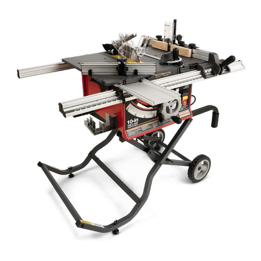
10 in, TABLE SAW
Model No.
315.218291
AL
o
A
WARNING:
To reduce the risk of injury,the
user must read and understand the operator's
manual before using this product.
Customer
Help Line: 1-800-932-3188
Product
distributed
in the United
States
by Sears
Brands
Management
Corporation
Hoffman
Estates,
IL 60179
Visit the Craftsman
web page: www.sears.com
988000-067
10-5-10 (REV:04)
Save this manual
for future
reference
C
Advertisement
Table of Contents

Related Manuals for Craftsman 315.218291


Summary of Contents for Craftsman 315.218291
- Page 1 Customer Help Line: 1-800-932-3188 Product distributed in the United States by Sears Brands Management Corporation Hoffman Estates, IL 60179 Visit the Craftsman web page: www.sears.com 988000-067 Save this manual for future reference 10-5-10 (REV:04)
-
Page 2: Table Of Contents
ONE YEAR FULL WARRANTY Oit (::;FIAFTSMA11 TOOL If this Craftsman tool fails due to a defect in material or workmanship within one year from the date of purchase. (::;all 1-800-4-MY-HOME ®... - Page 3 [] SECURE WORK. Use clamps or a vise to hold work WARNING: Read and understand all instruc- when practical. It's safer than using your hand and tions. Failure to follow all instructions listed below, frees both hands to operate tool. may result in electric shock, fire and/or serious [] DON'T OVERREACH.
- Page 4 [] STAY ALERT AND EXERCISE CONTROL. Watch BLADE COASTS AFTER BEING TURNED OFF. what you are doing and use common sense. Do not NEVER USE iN AN EXPLOSIVE ATMOSPHERE. operate tool when you are tired. Do not rush. Normal sparking of the motor could ignite fumes. [] DO NOT USE TOOL IF SWITCH DOES NOT TURN IT INSPECT TOOL CORDS PERIODICALLY.
- Page 5 [] NEVER perform anyoperation "freehand" which [] ALWAYS TURN OFF SAW before disconnecting it, to means usingonlyyourhands to supportor guidethe avoid accidental starting when reconnecting to power workpiece. Always useeither t he ripfenceor miter supply. gauge to position andguidethework. [] ONLY USE BLADES within the thickness range [] NEVER standor haveanypartofyourbody stamped on the spreader/riving knife.
-
Page 6: Symbols
Some of the following symbols may be used on this tool. Please study them and learn their meaning. Proper inter- pretation of these symbols will allow you to operate the tool better and safer. Indicates a potential personal injury hazard. Safety Alert To reduce the risk of injury, user must read and understand Read Operator's Manual... - Page 7 The following signal words and meanings are intended to explain the levels of risk associated with this product. SYMBOL SIGNAL MEANING Indicates an imminently hazardous situation, which, if not avoided, will DANGER: result in death or serious injury. Indicates a potentially hazardous situation, which, if not avoided, could WARNING: result in death or serious injury.
-
Page 8: Electrical
ELECTRICAL CONNECTION EXTENSION CORDS This tool is powered by a precision built electric motor. Use only 3-wire extension cords that have 3-prong ground- It should be connected to a power supply that is 120 ing plugs and 3-pole receptacles that accept the tool's plug. volts, 60 Hz, AC only (normal household current). - Page 9 Anti-Kickback Pawls (flooring, radial arm, and table Push Blocks (flooring and table saws) Device used to hold the workpiece during cutting opera- saws) A device which, when properly installed and maintained, tions. This aid helps keep the operator's hands well away from the blade.
- Page 10 PRODUCTSPECIFICATIONS Blade Arbor.............. 5/8 in. Input..............15Amps BladeDiameter ............10in. NoLoadSpeed ........4,800r/min.(RPM) Blade Tilt..............0° - 45° CuttingDepth at0°..........3-9/16in. Rating ..........120V,AConly, 6 0Hz CuttingDepth at45°..........2-1/2in. GUARD/DUST COVER WITH PIVOTASSEMBLY ANTI-KICKBACK PAWLS RIVING BLADE KNIFE GUARD ACCESSORY TABLE SLIDING MITER...
-
Page 11: Features
KNOWYOURTABLESAW HEIGHT/BEVEL ADJUSTING HANDWHEEL- Located See Figure 2. on the front of the cabinet, use this handwheel to lower and raise the blade for height adjustments or blade The safe use of this product requires an understanding replacement. This handwheel also makes the adjustment the information on the tool and in this operator's manual for bevel angles easy. - Page 12 OPERATING COMPONENTS WARNING: Always remove the switch key when Theupper portionofthebladeprojects upthrough the the tool is not in use and keep it in a safe place. tableandissurrounded b yaninsert c alledthethroat In the event of a power failure, turn the switch off plate.
- Page 13 BLADES WARNING: Do not use blades rated less than the For maximum performance, it is recommended that you speed of this tool. Failure to heed this warning could use the 36-tooth, 10 in. carbide-tipped combination blade result in personal injury. provided with your saw.
- Page 14 Thefollowing itemsareincluded withthetablesaw: Fig.5 A. Sliding MiterTable ............................. B. MiterFence withAdjusting Clamp ........................C. MiterGauge ..............................D. HexKey(1/8in.,3/16in.,3/32in.,5/32in.)......................E. Large Blade Wrench ............................R Small B lade Wrench ............................G. Accessory T able ..............................H. Bevel H andle Assembly ............................I.
- Page 15 Thefollowing items areincluded withthetablesawaccessory t able: Fig. 6 Guide Fence with Guide Block (left and right) ..2 Throat Plate (1-1/8 in.) ..........Flat Washer (1/4 in. x 16) ........Throat Plate (1/2 in.) ..........Screw, #10 in.-32 x 3/4 in ........Knob Bolt (1/2 in.) ...........
-
Page 16: Loose Parts
UNPACKING WARNING: Never stand directly in line with the This product requires assembly. blade or allow hands to come closer than 3 in. to the blade. Do not reach over or across the blade. Failure [] Carefully lift saw from the carton and place it on a level to heed this warning can result in serious _ersonal work surface. -
Page 17: Operation
WING NUT RELEASE LEVELING LEVER FOOT WHEEL STOP Fig. 9 TO STORE THE TABLE SAW ACCESSORIES See Figures 10- 11. The table saw has two convenient storage areas specifi- cally designed for the saw's accessories. These accesso- ries must be securely stored prior to closing the leg stand BRACE and moving the saw. - Page 18 Standfacingthebackofthetablesaw. T helongest p artof TO iNSTALL BEVEL HANDLE ASSEMBLY themitertablebasemustbestoredto the left.Tosecure See Figure 12. theslidingmiter table: [] Lift the end cap off the bevel handle assembly using a [] Rest t heslidingmitertableonthe bottomright-hand flat blade screwdriver. storage hookandthe miterbaseonthelowerbottom [] Hold the hex nut securely and turn the screw left-hand hook.
- Page 19 TO (NSTALL FRONT AND BACK RA(LS TO UNLOCK/MOVE THE RAILS See Figures 13- 14. See Figure 15. Loosen the front rail clamps one half turn from the The front and back rails will need to be positioned so they tightened position. Loosen the square rail holder nut do not touch the floor when the leg stand is closed.
- Page 20 TO CLOSE THE LEG STAND AND MOVE THE TO REMOVE/REPLACE THE THROAT PLATE See Figure 17. See Figure 16. [] Lower the blade by turning the height/bevel adjusting handwheel counterclockwise. Store the sliding miter table on the back of the saw cabinet.
- Page 21 TO CHANGEBETWEEN A SPREADER AND A RIV(NG KNIFE RELEASE LEVER See Figure 18. (UNLOCKED) A/._F'_"_'_.. This saw is shipped with the spreader/riving knife placed in the non-through cutting or "down" position (riving knife position). NOTE: The spreader/riving knife must be placed in the through cutting, or "up"...
-
Page 22: Adjustments
TO CHECK SAW BLADE INSTALLATION TO INSTALL THE BLADE GUARD AND ANTI- See Figure 19. KICKBACK PAWLS See Figures 20 - 22. CAUTION: To work properly, the saw blade teeth WARNING: Replace dull or damaged anti-kickback must point down toward the front of the saw. Failure to do so may cause damage to the saw blade, the pawls. - Page 23 TO CHECK AND ALIGN THE SPREADER/RIVING To install blade guard: [] Lift the guard lever up to unlock. KNIFE AND SAW BLADE See Figures 23 - 24. [] With the front of the blade guard raised, lower the back of the guard into the middle hole of the spreader/ To check a(ignment of the spreader/riving knife:...
- Page 24 Toadjust TO INSTALL THE SLIDING MITER TABLE AND (horizontally): Remove the blade guard assembly, anti-kickback MITER FENCE pawls, and the throat plate. See Figures 25 - 26. Raise the blade to its full height. [] Remove the sliding miter table from the storage area [] Turn the adjustment screws to reposition the spreader/ by pulling the miter locking clamps away from the saw cabinet.
- Page 25 ADJUSTING CLAMP TO CHECK SLIDING MITER TABLE ASSEMBLY MITER FENCE KNOB ATTACHMENT The square relationship between the blade and the miter fence as it travels the entire distance from the front to the HOLDER BOLT rear of the miter table base during a cut is very important for making precise and accurate cuts.
- Page 26 Kickback can be caused by any action that pinches the WARNING: Do not allow familiarity with tools to blade in the wood such as: make you careless. Remember that a careless frac- [] Making a cut with incorrect blade depth tion of a second is sufficient to inflict severe injury.
- Page 27 CUTTINGAIDS See Figure 29. Push sticks are devices that may be used for pushing a workpiece through the blade in any rip cut. When mak- ing non-through cuts or ripping narrow stock, always use a push stick, push block, and/or featherboard so your hands do not come within 3 inches of the saw blade.
- Page 28 FEATHERBOARD FEATHERBOARD PUSH BLOCK A featherboard is a device used to help control the workpiece by holding it securely against the table or fence. Featherboards are especially useful when ripping small workpieces and for completing non-through cuts. The end is angled with a number of short kerfs to give a friction hold on the workpiece and locked in place on the table with a C-clamp.
- Page 29 TYPESOF CUTS See Figure 34, © There are six basic cuts: 1) the cross cut, 2) the rip cut, CROSSCUT 3) the miter cut, 4) the bevel cross cut, 5) the bevel rip cut, and 6) the compound (bevel) miter cut. All other cuts are combinations of these basic six.
- Page 30 TO CHANGETHE BLADE DEPTH CHECKING SLIDING MITER TABLE AND See Figure 35. MAKING ADJUSTMENTS The blade depth should be set so that the outer points of TO CHECK MITER BASE PARALLELISM the blade are higher than the workpiece by approximately See Figures 37 - 38.
- Page 31 [] Remove f raming square andslidemitertableto the TO CHECK M(TER FENCE AUGNMENT rearof miterbaseasfaras itwill go. See Figure 39. [] Rotate the bladesothe reference m arkontheblade The miter fence must be perpendicular to the blade when isatthe rearof thethroatplate.Measuring f romthe set at zero degrees.
- Page 32 TO ADJUST THE MITER BASE TO ADJUST THE MITER FENCE See Figure 40. See Figures 41 - 42. Remember: Check all settings before loosening screws [] Set the miter fence (H) at 0 °. Miter indicator should be for the following procedures. Once screws have been set precisely on 0 °...
- Page 33 [] Tighten hexnutsecurely. QUICK STOP [] Adjustrightrearscrewfromunderneath m iter tableto remove excessive p lay. [] Tighten hexnutsecurely. [] Recheck y oursetupscarefully. Alsomakesureall screws, h exnuts,etc.,havebeen tightened securely. [] If slidingmiter tableassembly i s stillnotsquare with theblade,repeat t he above procedures a s needed. [] Makesurethatslidesremain square to miterbase ECCENTRIC edgeto prevent "...
- Page 34 [] Loosen the rip fence by lifting the locking handle. WARNING: To reduce the risk of injury, always [] Set the rip fence gently against the blade tip edge. make sure the rip fence is parallel to the blade [] Loosen the screw on the scale indicator and align with before beginning any operation.
- Page 35 MAKING CUTS This table saw can perform a variety of cuts that are not all mentioned in this manual. DO NOT attempt to make any SWITCH cuts not covered here unless you are thoroughly familiar with the proper procedures and necessary accessories. Your local library has many books on table saw usage and specialized woodworking procedures for your reference.
- Page 36 MAKING A RiP CUT MAKING A MITER See Figure 49. See Figure 50. WARNING: Make sure the blade guard assembly WARNING: Make sure the blade guard assembly is installed and working properly to avoid serious pos- is installed and working properly to avoid possible sible injury.
- Page 37 BEVELCROSSCUT MAKING A BEVEL CROSS See Figures 51 - 52. BLADE ANGLED WARNING: Make sure the blade guard assembly is installed and working properly to avoid possible serious injury. WARNING: The miter gauge (or miter fence) must be on the left side of the blade to avoid trapping the wood and causing kickback and the risk of serious personal injury.
- Page 38 [] Position theworkpiece flatonthetablewiththeedge [] Adjust the bevel angle to the desired setting. flushagainst t he ripfence. L etthe bladebuildupto full [] Lock the bevel locking lever. speedbefore feeding theworkpiece intotheblade. [] Set the blade to the correct depth for the workpiece. [] Oncethebladehasmadecontact w iththeworkpiece, [] Set the miter gauge (or miter fence) to the desired usethehandclosest t o theripfenceto guideit.
- Page 39 MAKING A LARGE PANEL CUT MAKING A NON-THROUGH See Figure 55. See Figure 56. Make sure the saw is properly secured to a work surface Non-through cuts (made with a standard 10 in. blade) can to avoid tipping from the weight of a large panel. be made with the grain (ripping) or across the grain (cross cut).
- Page 40 NON-THROUGH CUT [] Reinstall the blade nut. NOTE: The blade washer may be used provided the arbor shaft extends slightly beyond the arbor nut. GUARD PUSH [] Make sure the blade nut is fully engaged and the arbor BLADE REMOVED STICK extends past a securely tightened blade nut.
- Page 41 T-NUTBETWEEN This accessory table has been specifically designed for ADJUSTMENT SCREWS use with some Craftsman Routers. The hole pattern on the accessory table has not been drilled to accommodate all routers. Routers must not exceed 3 HP (maximum developed) or weigh more than 12-1/2 Ibs. Routers must have lock-on switch feature.
- Page 42 iNSTALL T-NUTS FROMBEAROF HiP FENCE TO iNSTALL POST, GUARD/DUST COVER WITH PIVOT ASSEMBLY See Figure 61. The guard/dust cover must be used in all routing opera- tions. T-NUT [] Place the spacer on the threaded end of the post and thread the post into the remaining T-nut.
- Page 43 TO INSTALLROUTER Select the correct size throat plate for the size of the router bit. Align the tab on the throat plate with the See Figure 62, slot in the router extension and snap in place. Make Unplug the router. sure the throat plate is firmly seated below the table Place your router upside down on a workbench.
- Page 44 BLADE BLADE LARGE SMALL WARNING:Before performing a nyadjustment, WASHER WASHERSPACER makesurethetool is unplugged f romthe power supply andtheswitchis inthe offposition. F ailure to heed this warning could result in serious personal injury. The table saw has been adjusted at the factory for making very accurate cuts.
- Page 45 TO SET THE BEVEL INDICATOR AND BEVEL [] If the blade is not an exact 45 °, loosen the lock nut on the 45 ° bolt inside the cabinet, position the blade, STOPS AT 0 ° AND 45 ° (SQUARING THE BLADE) adjust the bolt, then retighten lock nut.
- Page 46 TO ADJUST THE BEVEL LOCKING LEVER TO CHECK THE ALIGNMENT OF THE RIP FENCE TO THE BLADE See Figure 70. See Figure 69. The bevel locking lever may work loose and require adjusting. To adjust: Unplug the saw. [] Unplug the saw. Raise the locking handle to permit the rip fence to be moved.
- Page 47 RAIL HOLDER TO AL(GN THE MITER LOCKING CLAMPS See Figure 71. The miter locking clamps are preset at the factory but may RAiL require adjusting after extended use or if damage occurs CLAMP in shipping. Unplug the saw. Loosen the set screw behind each locking clamp. WASHER Loosen the screw on top of each locking clamp.
-
Page 48: Maintenance
LOCKER BRACKET ASSEMBLY WARNING: When servicing, use only identical See Figure 74. replacement parts. Use of any other parts can create [] Add dry lube between both bevel gears, the backup a hazard or cause product damage. washers, and the locker bracket. [] Add drylube between threaded hole in motor casting WARNING: Always wear eye protection with side... - Page 49 , PROBLEM CAUSE SOLUTION Excess vibration. Blade is out of balance. Replace blade. Replace blade. Blade is damaged. Saw is not mounted securely. Tighten all hardware. Work surface is uneven. Reposition on flat surface. Adjust legs of optional stand. Blade is warped. Check saw blade installation.
- Page 50 I PROBLEM CAUSE SOLUTION Wood edges away from rip Rip fence is misaligned. Check and adjust the rip fence. fence when ripping. Blade not properly sharpened or Resharpen or set blade. set. Sliding miter table assembly Miter base or slides improperly See page 30 for adjustments to sliding does not move smoothly, adjusted,...
- Page 51 CRAFTSMAN 10 in. TABLE SAW - MODEL NO. 315.218291 regarding your TABLE SAW or when ordering repair parts. The model number will be found on a label attached to the side panel of the cabinet. Always mention the model number in all correspondence...
- Page 52 CRAFTSMAN 10 in. TABLE SAW - MODEL NO. 315.218291 regarding your TABLE SAW or when ordering repair parts. The model number will be found on a label attached to the side panel of the cabinet. Always mention the model number...
- Page 53 CRAFTSMAN 10 in. TABLE SAW - MODEL NO. 315.218291 regarding your TABLE SAW or when ordering repair parts. The model number will be found on a label attached to the side panel of the cabinet. Always mention the model number...
- Page 54 CRAFTSMAN 10 in. TABLE SAW - MODEL NO. 315.218291 regarding your TABLE SAW or when ordering repair parts. The model number will be found on a label attached to the side panel of the cabinet. Always mention the model number in all correspondence...
- Page 55 CRAFTSMAN 10 in. TABLE SAW - MODEL NO. 315.218291 regarding your TABLE SAW or when ordering repair parts. The model number will be found on a label attached to the side panel of the cabinet. Always mention the model number...
- Page 56 CRAFTSMAN 10 in. TABLE SAW - MODEL NO. 315.218291 regarding your TABLE SAW or when ordering repair parts. The model number will be found on a label attached to the side panel of the cabinet. Always mention the model number in all correspondence...
- Page 57 CRAFTSMAN 10 in. TABLE SAW - MODEL NO. 315.218291 regarding your TABLE SAW or when ordering repair parts. The model number will be found on a label attached to the side panel of the cabinet. Always mention the model number...
- Page 58 CRAFTSMAN 10 in. TABLE SAW - MODEL NO. 315.218291 regarding your TABLE SAW or when ordering repair parts. The model number will be found on a label attached to the side panel of the cabinet. Always mention the model number in all correspondence [""...
- Page 59 CRAFTSMAN 10 in. TABLE SAW - MODEL NO. 315.218291 regarding your TABLE SAW or when ordering repair parts. The model number will be found on a label attached to the side panel of the cabinet. Always mention the model number...
- Page 60 CRAFTSMAN 10 in. TABLE SAW - MODEL NO. 315.218291 regarding your TABLE SAW or when ordering repair parts. The model number will be found on a label attached to the side panel of the cabinet. Always mention the model number in all correspondence...
- Page 61 CRAFTSMAN 10 in. TABLE SAW - MODEL NO. 315.218291 regarding your TABLE SAW or when ordering repair parts. The model number will be found on a label attached to the side panel of the cabinet. Always mention the model number...
- Page 62 CRAFTSMAN 10 in. TABLE SAW - MODEL NO. 315.218291 regarding your TABLE SAW or when ordering repair parts. The model number will be found on a label attached to the side panel of the cabinet. Always mention the model number in all correspondence ===J 1_ _ _.-.--_ 13...
- Page 63 CRAFTSMAN 10 in. TABLE SAW - MODEL NO. 315.218291 regarding your TABLE SAW or when ordering repair parts. The model number will be found on a label attached to the side panel of the cabinet. Always mention the model number...
- Page 64 CRAFTSMAN 10 in. TABLE SAW - MODEL NO. 315.218291 regarding your TABLE SAW or when ordering repair parts. The model number win be found on a label attached to the side panel of the cabinet. Always mention the model number in all correspondence...
- Page 65 CRAFTSMAN 10 in. TABLE SAW - MODEL NO. 315.218291 regarding your TABLE SAW or when ordering repair parts. The model number will be found on a label attached to the side panel of the cabinet. Always mention the model number...