Table of Contents
Advertisement
_
WARNING:
To reduce the risk of injury, the
user must read and 'Jnderstand the operator's
manual before using this product.
Customer
Help Line: 1-800-932-3188
Sears, Roebuck and Co., 3333 Beverly Rd., Hoffman Estates, IL 60179 USA
Visit the Craftsman web page: w_,.sears.com/craftsman
983000-696
6-30-05
Save this manual for future reference
Advertisement
Table of Contents

Related Manuals for Craftsman 315.218060


Summary of Contents for Craftsman 315.218060
- Page 1 'Jnderstand the operator's manual before using this product. Customer Help Line: 1-800-932-3188 Sears, Roebuck and Co., 3333 Beverly Rd., Hoffman Estates, IL 60179 USA Visit the Craftsman web page: w_,.sears.com/craftsman 983000-696 Save this manual for future reference 6-30-05...
- Page 2 ..............................43-50 _a Parts Ordedncj/Service ............................ Back Page ONE YEAR FULL WARRANTY ON CRAFTSMAN TOOL If this Craftsman tool fails due _o a detect in material or workmanship within one year from the dale of purchase. Call 1-800-4-MY-HOME ® to arrange...
- Page 3 A WARNING: i_ SECURE WORK. Use clamps or a visa to hold wed{ Read and understand all ]nstruc- when practical. It's safer than using your hand and gone. Failure to follow all instructions listed below, frees both hands to operate tool may result in electric...
- Page 4 work or around or over the blade while blade is ing. Never use brake fluids, gasoline, petroleum-based rotating. Do not attempt to remove cut material when products, or any solvents to clean tool, blade is moving, STAY ALERT AND EXERCISE CONTROL, Watch [] BLADE COASTS AFTER BEING TURNED OFF.
- Page 5 AVOID AWl{WARD OF'ERATIONS AND HAND f_ NEVER perform any operation "|reehand" which POSITIONS where a sudder_ slip could cause your means using only your hands to support or guide hand to m,_ve into the cutting tool workpiece, Always use either the rip tence or miler USE ONLY RECOMMENDED...
- Page 6 Some of t he f ollowing symbols may be used on this t ool Please study them a nd l earn their meantng, Proper • interpretation ofthese symbols will allow you t ooperate the t ool better and safer, SYMBOL NAME DESIGNATION/EXPLANATION Vogs...
- Page 7 The following signal words and meanings are intended to explain the levels of nsk associated with this eroduct SYMBOL SIGNAL MEANING Indicates an imrninent!y hazardous siluatlon, which, if not avoided, will DANGER: result in death or $er cos iiljury, indicates a potenhaliy hazardous situat...
- Page 8 EXTENSION CORDS ELECTRICAL CONNECTION Use only 3-wire extension cords that have 3-prong This tool is powered by a precision buitl electric motor. grounding plugs and 3-pole receptacles that accept the It should be connected to a power supply that Is 120 volts, 60 Hz, AC only [normal household current}.
- Page 9 • 'i ..i _ :. :: Anti-Kickback Pawls (radial arm and table saws) Non-Through Cuts Any cutting operalien where the blade does not extol d A device which, when properly installed and maintained completely through the thickness of the workpiece. is designed to stop the workplace from being kicked back toward the front of the saw during a ripping operation.
- Page 10 PRODUCT SPECIFICATIONS Blade Arbor .............. 5/8 in. Rating ..........120 V, 50 Hz, AC Blade Diameter ............10 in. Input ..............15 Amper_ Blade Tilt ..............O ° * 45° No Load Speed ..........5,000imi Net Weight without Leg Stand ......61,5 Ibs. Cutting Depth at 0°: ........
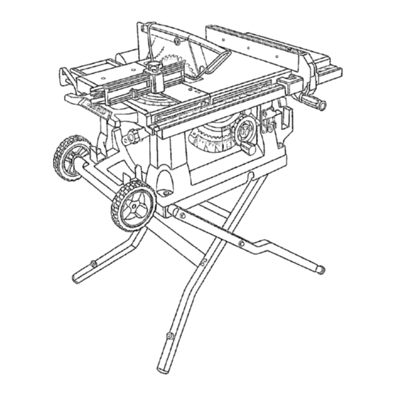
- Page 11 KNOW YOUR TABLE LEG STAND * Attached to the table saw base, the le stand ooens ano ClOSeS WIUq ease. See Figure 2. MITER FENCE- The fence attaches to the sliding rrli Before attemptin G to use fins aroduct, faml iarize yourself table and can be angled for miter and comsound...
- Page 12 -•- • • • OPERATING COMPONENTS WARNING: Atways remove the switch key when The upper podioo of the blade pro}ects up through the _he tool is not in use and keep it in a safe place. Ir tabie and is staTounded by an insert called the throat the event of a power faiture, turn the switch OFF plate.
- Page 13 Do no_ use blades raled less than For maximum performance, it is recommended that ould speed of this tool. Failure to heed this warning ( use the Craftsman 36-tooth, 10 in. carbide combination result in personal injury. blade provided with your...
- Page 14 The following items are included wilh your table saw: Rip Fence ................................... Large Blade Wrench ..............................C. Smalt Blade Wrench ..............................D, Elbow .................._................Dust Bag ................................E Bevel HandleAssembly ............................G. Miter Fence wi[h Adjusting Clamp ........................... H. Blade Guard with Spreader and Anti-Kickback Pawls ....................
- Page 15 UNPACKING MOUNTING HOLES This product requires assembly. This toot comes mounled to a leg stand. ]f you chose remove the leg stand, the table saw must be mounted IJ Carefully lift saw from the carton and place it on a level work sudace.
- Page 16 TO OPEN/CLOSE TEAR DOWN (SET-UP/TEAR DOWN) THE LEG STAND See Figure 7. To open (set-up} tt_e leg stand: m Step l:Withthe saw table on endand standing to theside, use your left hand to pull the _egstand latch towards you. 13 Sten 2: Once the leg stand is released from the table saw base, ease the legs of tl_e sland down.
- Page 17 TO MOVE THE LEG STAND TO STORE TABLE ACCESSORIES SeeFigures See Figure 10. To move the leg stand: The table saw has two convenient storage areas (one on either side ot the saw cabinet) specifically desigt_ed Holdin 9 _#i e the _egstand t_waldl S[_d _r_,...
- Page 18 TO CHECK SAW BLADE INSTALLATION TO INSTALL MITER FENCE See Figure !2 See Figure 13. Remove the miter fence from the miter fence storafje CAUTION: To work properly, the saw blade teeth oh the side af the saw cabinet. must point down toward tile...
- Page 19 INSTALL BLADE GUARD ASSEMBLY AIITI-KICKBAI_K See Figure PAWLS Prober installation of the blade guard assembly means that the saw blade and spreader are in aligrlmenl. ALWAYS align the spreader to the saw blade prior to turn ing on the table saw. Lower the blade.
- Page 20 APPLICATIONS You may use t his t ool for t he p urposes listed below: Straight line c utting operations such as cross cutting, ripping, mitering, beveling, and c ompound culting _ Dadc or molding outs with o ptional accessories [] Cabinet making and w oodworldng...
- Page 21 T'_'PES OF CUTS See FTgure17 There are six basic cuts: 1) the cross cut, 2) the rip cut, 3) the miter cut, 4) the bevel cross cut, 5) the bevel rip cut, and 6) the compound (bevel) miter cut. All other cuts are combinations of these basic six.
- Page 22 FEATHERBOARD HOW TO MOUNT A FEATHERBOARD A featherboard is a device used to belp control the See Figure 19 workpiece by guiding it securely against the table or Remove the adjusting clamp knob, bolt, and washer fronq fence. Featherbeards are especially useful when ripping the miter fence holder.
- Page 23 ..TO CHANGE BLADE DEPT_ CHECKING SLIDING MITER TABLE AND See Figure 20. tVIA_(ING ADJUSTMENTS The blade depth should be set so that the outer points cff TO POSITION THE SLIDING MITER TABLE tile blade are higher than the workpiece by approximately See Figures 22- 23 1/8 in.
- Page 24 Fig. 23 CI-IEOK MITER BASE PARALLELISM See Figures 24 - 25. _a Unplug the saw. B Set saw up as if you were preparing to make a cut. Tighten rail ciamps, miter locking clamps, adjusting clamp, etc, Fig,241 Slide miter table (A) to the front of miter base (B) as far as it will go.
- Page 25 TO ADJUST THE M ITER BASE TO CHECK MITER FENCE ALIGNMENT See Figure See Figure The miter fence must be perpendic_llar to the blade w_!in Remember: Check a{I settings before loosening screws for the following p:ocedures, Once screws have been set at zero degrees.
- Page 26 TO ADJUST QUICK-STOP SCALE BLADE FENCE See Figure 28 The quick-stop is preset at the factory to stop the miter fence at exactly 0°, However, when sliding miter table adluslments are made, these adjustments may cause the quick-stop to need adjusting. Ci_eck quick{ stop with miter scale set at 0 _, If adjustments are needed, proceed with lhe folIowing steps: B Loosen the eccentric screw holding the quick stop.
- Page 27 TO USE OUTFEED SUPPORT See Figure 31. The ouLffeedsuopod slides to give the operator additional support for cutting long workpieces. m With the table saw in the OFF position, stand behind the saw. 13 Grasp the outfeed suppod with both hands and pull it ur_t_l it is _ulb]extended TO USE THE TABLE EXTENSION See Figure 32...
- Page 28 HEELING (PARALLELING) THE BLADE See Figures33 -35. _'_ WARNING: The blade must be square so the wood does not bind resulting in kickback, Failure to do so could result in serious personal injury. Do not loosen any screws for 1his adjustment uf_ti!yot_ have checked with a square and made test cuts to be sure adjustments are necessary.
- Page 29 MAKING CUTS The blade provided with lhe saw is a high-quaiity combi- nation blade suitable for ripping and cross cut operations. WARNING: Do not use blades rated tess than the speed of this tool. Failure to heed this warning could result in personal il,iury.
- Page 30 Place asupport (the same height as saw table) behind MAKING A MITER the saw f or t he c ut work, See Figure 39. Make sure the w ood IscIear of t he b lade before turning It is recommended you make test cuts on scrap wood. = on the s aw.
- Page 31 VIEWEDFROr_THE FRONT, B ELOWTHETABLE SAW MAKING A BEVEL RiP CUT HEIGHTIBEVEL See Figure 42. ADJUSTING It is recommended you make test cuts oil scrap wood. HANOWHEEL TO LOOSEN WARNING: The np fence must oe on the let. side of the blade to avoid trapping the wood and c_usinil kickback.
- Page 32 When the cut is made, turn the saw off. Wait Ior the la Loosen tile lock knob on the miler gauge, sel the blade to come to a complete stop be[ore _emoving tire gauge to the desired angle and tighten the lock km_ workplace.
- Page 33 MAKING A LARGE PANEL MAKING A NON-THROUGH See Figure 44. See Figure 45, Make sure the saw is p_opetly secured ta a work surface Non-through cuts can be made with the grain (ripping) _1 to avoid lipping from the weight of a large panel. across the grain (cross cut}, The use of a non-through cU is essential to cutling grooves, rabbets, and dadoes.
- Page 34 MAKING A DADO CUT ,& WARNING: Never feed wood with your hands when See _Tgute 46. making any nan through cut such as rabbets As optional dado throat plate (part number 0134011_! dadoes. To avoid personal iniury, always use push is requi_ed for tills procedure.
- Page 35 WARNING: Before performing any adjustment, make sure the fool is unplugged from the power supply. Faiture to heed this warning could result serious personal injury. ABBOR SHAFT WARNING: Blades coast after turn off. Possible serious injury can occur if hands come m conlac! with blade.
- Page 36 TO CHECK AND ALIGN THE SPREADER, TO CHECK THE ALIGNMENT OF THE RIP FEN_ BLADE, AND BLADE GUARD ASSEMBLY TO THE BLADE See Figure 50 See F_?ure 51. If the blade guard assembly is out of alignment with the Unplug the saw. saw blade, adjust the alignment of the blade g[Jard e Raise the locking lever to permit the rip fence to be assembly.
- Page 37 B If the two dimensions are not the same, loosen the two screws on the fence and align it. B Retighten the two screws. 8 Make two or three test cuts on scrap wood. If the cuts are trot true, repeat the process. WARNING: Before plugging...
- Page 38 L_ Periodically check all clam WARNING: When servicing, use only identical bolts for tightness and condition. replacement parts. Use of any other parts may create plate is in good condition and in position. a hazard or cause product damage. Check the blade guard assornbly. [] To maintain the table sudaces, fence, and rails, WARNING: Always wear safety goggles or safety...
- Page 39 PROBLEM CAUSE SOLUTION Excess vibration. Blade is out el balarce. Replace blade. Blade is damaged. Replace blade. Saw is not mour_led securely. Tighten all hardware. Work surface is uneven. Reposition on fiat SlJdace Adjusl legs of optional stand Check saw bJade insta latices. Replace blade i Blade is warped necessary, Rip fence does not move...
- Page 40 • • • • • • I PROBLEM CAUSE SOLUTION Saw d oes not make accurate Positive stops inside cabinet need Adjust positive stops. gO' or 4 5' cuts. adjusting (Bevel Cuts). Miter gauge ismisaligned (Miter Adjust the m iter gauge• Heighbtbevel adjusting hand- Gears...
- Page 41 CRAFTSMAN 10 in. TABLE SAW - MODEL NO. 315,218060 -'/, . ",:- Figure B 49--4 Figure A ._105 NOTE : The assembly shown represents an important part of the double insulated syslem. To avoid possibility of alteration or damage to the system,...
- Page 42 CRAFTSMAN 10 in. TABLE - MODEL NO. 315.218060 The model number will be found on a plate attached to the motor housing. Always mention the model number n a correspondence regatdin 9 your Table Saw or when order ng repa r paris.
- Page 43 CRAFTSMAN 10 in. TABLE SAW - MODEL NO, 315.218060 The model number will be found on e plate attached to the motor housing number in all correspondence regarding your Tab e Saw or when ordering repair parts. Always mentioiq the model...
- Page 44 CRAFTSMAN 10 in. TABLE SAW - MODEL NO, 315.218060 FIGURE A: SLIDING MITER TABLE Key Part Number Description Qty. A134010802 Sliding Miter Table Assembly (incl. Key No. 1 - 8) 410561013" "Screw w/Washer (MSx 16 mini .,..4 2 0134010104-126 MiterTabie ........1 3 0134010910 Locking Pin .........
- Page 45 Part Number Description Qty. A134014001 Height/Bevel Adjusting Handwheel Assembly ..........1 00001 !0812 Nut (1/4 in. - 20) ......0134010221-130 BeightLBevel Adjusting Handwheel ......... 412012041 Flat Washer (6+5 x 13 x 1.57)..1 0121010223 Bevel Handle ......0101140203 Screw ......... 0121010224 End Cap, Bevel Handle .....
- Page 46 CRAFTSMAN 10 in. TABLE - MODEL NO. 315.218060 ¼ 3s-4,' -,:. REPLACEMENT PARTS LEG STAND ASSEMBLY Key Pa_ Number Number Description Qty, Description Qty. 0131011301 410031714 Leg Stand Latch ....... "Boil (5/8-11 x 88.9 ram) ... 1 O131O10322 0131010236 Plale ..........
- Page 48 Get it fixed, at your home or ou 's! Your Home For repair-in your home of all major brand appliances, lawn and garden equipment, or heating and cooling systems, no matter who made it, no matter who sold it! For the replacement pads, accessories and owner's manuals that you need to doqt-yourself.