Table of Contents
Advertisement
Caution:
Read and follow
all Safety Rules
and instructions
Before Operating
This Equipment
©
®
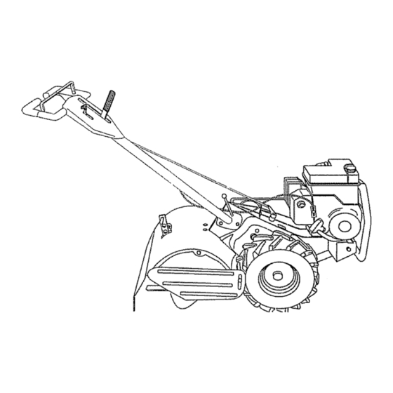
6.0 HP
17 iNCH TINE WIDTH
TU
TULLER WiTH
COUNTER F_OTATI
TIN
®Assembly
- Operation
Customer
Responsibilities
o Service and Adjustments
, Repa_r Parts
i iii
,, i
i i
.................................
i
,1111,1,,111,,111111,,i,i
Sears, Roebuck and Co., Hoffman
Estates,
IL 60179 U.S.A.
i,
ii
,, iii
Advertisement
Table of Contents

Related Manuals for Craftsman 917.293650


Summary of Contents for Craftsman 917.293650
- Page 1 © ® 6.0 HP Caution: 17 iNCH TINE WIDTH Read and follow all Safety Rules TULLER WiTH and instructions COUNTER F_OTATI Before Operating This Equipment ®Assembly - Operation Customer Responsibilities o Service and Adjustments , Repa_r Parts i iii ,, i .........
- Page 2 SAFETY RULES Safe Operation Practices for Walk-Behind Powered Rotary Tillers TRAINING Keep children and pets away Read the Owner's Manual carefulty_ Be thoroughly • Do not overload the machine capacity by attempting to familiar with the controls and the proper use of the till too deep at too fast a rate.
-
Page 3: Customer Responsibilities 3
Repairs necessary because of operator abuse or negligence, including bent crankshafts and the failure to maintain the equipment according to the instructions contained in the owneCs manual. If this Craftsman Tiller is used for commercial or rental purposes, this Warranty applies for only 30 days from the date of purchase. - Page 4 u nl ,,in,nl lun , TABLE OF CONTENTS 'll'n"lllHirll' i 'u nllu Ull'UlU''' i' i SAFETY RULES ............MAINTENANCE SCHEDULE ........SERVICE & ADJUSTMENTS ......... 15-18 CUSTOMER RESPONSIBILITIES ...... 3,13-15 PRODUCT SPECIFICATIONS ........STORAGE ..............TROUBLESHOOTING ..........WARRANTY ..............REPAIR PARTS-TILLER ........
-
Page 5: Accessories
.......... i,, 'IMIIIIIIIII ACCESSORIES ii, i ii '111, iii, ,111 ....These accessories were available when the tiller was purchased. They are also available at most Sears Retail outlets and Service Centers. Most Sears Stores can order repair parts for you when you provide the model number of your tiller= ENGINE ENG'i'NE"'O'iL... - Page 6 i ii i ii ............Your new flier has been assembled at the factory with exception of those parts left unassembled for shipping purposes ensure safe and proper operation of your tiller all parts and hardware you assemble must be tightened securely Use the correct tools as necessary to insure proper tightness TOOLS REQUIRED...
- Page 7 ,,11,,,,,i, ....,..1,1,1 L'L_ ASSEMBLY ..... ,,,i,i1,,,,,i,i, ,i,i1,,,,,i,,,i,ii, ii, , i , , UNPACKING CARTON (See Fig, 2) HoIdin"up"position. Be sure Grasp handle assembly, handle lock remains in gearcase notch, Slide handle assembly into position,, ",j._., _:,: "UP" POSITION ,_,:: .:_,_ +,j.f,_f...
- Page 8 REMOVE TILLER FROM CRATE CONNECT SHIFT ROD (See Fig. 6) Insert end of shift rod farthest from bend into hole of Adjust handte assembyto lowest position, Be sure lock shift lever indicator. lever is tightened securely° • Insert hairpin clip through hole of shift rod to securer Make sure shift lever indicator is in "N"...
-
Page 9: Depth Stake
,.i ..,..I" "'111"'11'11'""='"1'""11'1"1 ..I1'1 I1'11"11"1'1111 , , ,I,,,,,,,I,, "1"'11'1' ' OPEF ATmON ....,,.. ,,, i i, i ii iii, ,i, ,i,,i,,,i,M'IIII "11'"'1''11I KNOW YOUR TILLER READ THIS OWNER'S MANUAL AND SAFETY RULES BEFORE OPERATING YOUR TILLER, Compare the illustrations with your tiller to familiarize yourself with the location of various controls and adjustments, Save this manual for future reference°... - Page 10 The operation of any tiller can result in foreign objects thrown into the eyes, which can result in severe eye damage. Always wear safety glasses or eye shields before starting your tiller and while tilling. We recommend a wide vision safety mask over the spectacles or standard safety glasses.
- Page 11 ..=,, = ,,H, ,= ..=,, ,,,=,,,,,H, OPERAT!ON , = , =,m u u, 1, , lu,,,H ..TURNING • To read proper'level, tighten engine oil cap each time. • Reinstall engine oil cap and tighten. Release the drive control bar, •...
- Page 12 OPERATUON i, ,,,11 TO START ENGINE (See Fig. 7) Soil conditions are important for proper tilling° Tines will not readily penetrate dry, hard soil which may contrib- ute to excessive bounce and difficult handling of your tiller° Hard soi! should be moistened before tilling;...
- Page 13 ...., .., ..ii,, ,,,=..CUSTOMER RESIPON BILUTIES , , =,,H=..........SCHEDULE REGULAR SERVICE ,= ,,= H,= ..H= HH Check Engine 0it Level =lull Ill, Change Engine Oil 1_1,2 = ,H , 111 ....Oil Pivot Points Inspect Spark Attester / Muffler Inspect AIr Screen =ui!==,=...
-
Page 14: Air Cleaner
,_ ..... n,,,,, i,, ,,i CUSTOMER RESPONSBB L TmES ,, ii,lll,r,t Disconnect spark plug wire before performing any maintenance (except carburetor adjustment) to prevent accidental starting of engine. Preventfires{ Keep the engine free of grass, leaves, spiliedoil, orfuel. Remove fuel from tank before tipping unit for maintenance. - Page 15 IH ,I,H,I, CUSTO ESPONSBBmLmTIES ,,,, , ii,i i ,i ,ml,m i1,1 m,ii MUFFLER TRANSMISSION Your transmission is sealed and will only require lubrication Do not operate tiller without muffler.. Do not tamper with if serviced, exhaust system. Damaged mufflers or' spark arresters could create a fire hazard°...
-
Page 16: Belt Guard
, iiiiil,,,u,,ul , ,,11,,i SERVmCE AN ADJUSTMENTS i1,, TO REPLACE GROUND DRIVE BELT (See TO REMOVE (See Fig. 22) BELT GUARD Figs. 22 and 23) • Remove L.H, inner and outer side shields (See "TO Remove belt guard (See''TO REMOVE BELT GUARD" REMOVE WHEEL"... - Page 17 =,n, = ,=,,,,,,===,_ AND ADJUSTMENTS SERVICE To maintain the superb tilling performance of this TINE REPLACEMENT (See Figs. 24, 25 and 26) machine the tines should be checked for' sharpness, ,,i ,11 ii i1,1.i,. wear, and bending, particularly the tines which are next to the transmission.
- Page 18 ENGINE TO ADJUST CARBURETOR The carburetor has been preset at the factory and adjust- TO ADJUST THROTTLE CONTROL CABLE ment should not be necessary, However, engine perfor- (See Fig. 27) mance can be affected by differences in fuel, temperature, altitude or load, If the carburetor does need adjustment,...
- Page 19 ENGINE Immediately prepare your tiller' for storage at the end of the season or if the unit will not be used for 30 days or more. Drain eli (with engine warm) and replace with clean oil. = ,,,,i ..(See "ENGINE" in the Customer Responsibilities section of CAUTION: Never store the tiller with...
- Page 20 I'H'""H" I" I" I TROUBLESHOOTING POINTS iii i, i,i P,,,ll , , ,, , LILI,]I','U"I'Nr,L' ,1,', ....PROBLEM CAUSE CORRECTION Fill fueftank Wli! not start Out of fuel See '3"0 START ENGINE" in Operation section Engine not "CHOKED" propedy Engine flooded Wait several minutes before attempting to start Dirty air cleaner Clean or replace air cleaner cartridge...
- Page 21 REPARRPARTS TALLER - - MODEL NUMBER 917.293650 HANDLES _--.:,_ -,'_7-.- _- • t;% 31 \ DESCRIPTION DESCRIPTION PART PART Washer 13/32 x 1 x tl Gao 19131611 127012X Throttle, Control 109228X Lever, Lock, Handle 141406 Grip, Handle 150258 Handle, Assemble 110673X Grommet, Handle 121145X...
- Page 22 REPAURPARTS TILLER - - MODEL NUMBER 917.293650 MAINFRAME, LEFT SIDE PART DESCRIPTION STD54!431 Nut, Keps 5/t6-18 STD551137 *Washer, Lock 3/8 STD541037 * Nut, Hex 3/8-16 74930568 Bolt, Hex 5/16-18 x 4-1/4 154734 Screw Shift Lever 110111X Lever, Shift STD532505 * Bolt, Carriage 1/4-20 x 1/2 Gr.
-
Page 23: Repair Parts
102332X Bracket, Reinforcement STD541431 * Nut, Keps 5/16-18 74760532 Bolt, Hex 5/16-18 x 2 ..Engine, (See Breakdown) Craftsman Model No. 143.976001 102173X Counter Weight, R.H. STD551137 * Washer, Lock 3/8 * STANDARD HARDWARE - - PURCHASE LOCALLY STD541037 * Nut, Hex 3/8-16... - Page 24 REPAnB PARTS TgLLER - - MODEL NUMBER 9'17.293650 TRANSMISSION PART DESCRIPTION STD541143 * Nut, Hex 7/16-20 143009 Bearing, Shaft, Ground Drive LrH. 106390X Spacer 0.765 x 1.125 x 1.23 102134X Chain #35-50 Pitch PART DESCRIPTION 150737 Ground Shaft Assembly 143008 Bearing, Shaft, Ground Drive R.H.
- Page 25 REPAIR PARTS TILLER -- MODEL NUMBER 917.293650 TINE SHIELD 25 16 DESCRIPTION PART PART DESCRIPTION STD532512 * Bolt, Carriage 1/4-20 x 1-1/4 Gr. 5 98000129 Nut, Flange 5/t6-18 102701X Grip 104086X574 Shield, Side, Outer L.H. STD541037 * Nut, Hex 3/8-16 8393J Pin, Stake, Depth 102156X...
- Page 26 REPABR PARTS TILLER -- MODEL NUMBER 917.293650 TINE ASSEMBLY "\ PART DESCRIPTION PART DESCRIPTION 74610616 4459J Bolt, Hex 3/8-24 x 1 Tine, Outer, Loll.. 4460J 132673 Tine, Outer, R.Ho Pin, Shear t32728 6554J Tine, Inner, L,.H. Assembly, Hub and Plate, RH 6555J STD624008 Tine, Inner, R.Ho...
- Page 27 REPAIR PARTS TILLER -- MODEL NUMBER 917.293650 DECALS °\ © DESCRIPTION PART 158095 Decal, Logo 145023 Decal, Logo 157982 Decal, Logo 157983 Decal, Description 137538 Decal, Caution, Drive Control 120431X Decal, Hand Placement 102180X Decal, Shift Indicator 157984 Decal, Ccu. Tines Rot. Tines 120075X Decal, Warning, Rotating Tines 158309...
- Page 28 REPARR PARTS TILLER - - MODEL NUMBER 917.293650 ENGINE, CRAFTSMAN -- MODEL NUMBER 143.976001 310 -- 245A...
- Page 29 REPAIR PARTS TILLER -- MODEL NUMBER 917.293650 ENGaNE, CRAFTSMAN - - MODEL NUMBER 143.976001 400¸ 370A 261A...
-
Page 30: Throttle
REPAnR PARTS TBLLER -- MODEL NUMBER 9'17.293650 ENGINE, CRAFTSMAN -- MODEL NUMBER 143.976001 KEY PART KEY PART NO. NO. DESCRIPTION NO. NO. DESCRIPTION 36866 Cylinder (lnci 2, 20 & 72) 173 36675A Breather Tube 26727 owel Pin 178 650852 Nut, 1/4-20 1"... - Page 31 PARTS REPAIR TILLER - - MODEL NUMBER 917.293650 ENGnNE, CRAFTSMAN -- MODEL NUMBER 143.976001 KEY PART DESCRIPTION 640025 Carburetor (lncI 184 or Engine Parts list) 631615 Throttle Shaft & Lever Assembly 631767 Throttle Return Spring 631184 Dust Seal Washer 631183...
-
Page 32: Tines
® 8.0 HP 17 INCH TINE WIDTH EAR T! TILLER WITH OOLINTEFI ROTATING TINES MODEL NO= Each tiIler has its own model number. Each engine has its own model number. 917.293650 The model number for your tiller will be found on a plate attached to the top of the transmission.