Table of Contents
Advertisement
Available languages
Available languages
Owner's Manual
JCRRFTSMIIW J
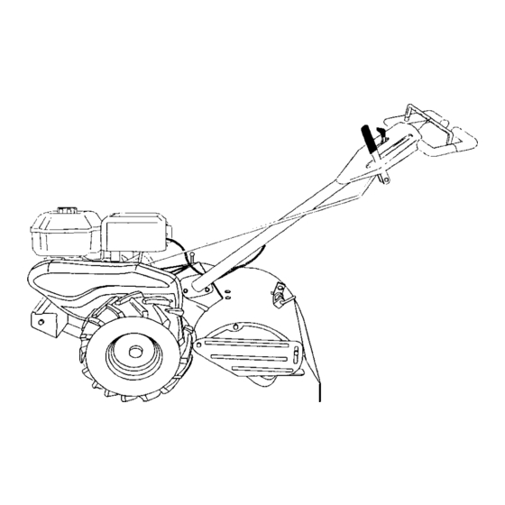
REAR TINE TILLER WITH
COUNTER ROTATING TINES
6.5 HP
17 Inch Tine Width
Model No.
This product has a low emission engine which operates
differently from previously built engines. Before you start the
engine, read and understand this Owner's Manual.
CAUTION:
Read and follow all Safety
Rules and Instructions before
operating this equipment.
Sears, Roebuck and Co., Hoffman Estates, II 60179 U.S.A.
Visit our Craftsman
website:www.sears.com/craftsman
Advertisement
Table of Contents

Related Manuals for Craftsman 917.293483


Summary of Contents for Craftsman 917.293483
- Page 1 This product has a low emission engine which operates engine, read and understand this Owner's Manual. CAUTION: Read and follow all Safety Rules and Instructions before operating this equipment. Sears, Roebuck and Co., Hoffman Estates, II 60179 U.S.A. Visit our Craftsman website:www.sears.com/craftsman...
- Page 2 • If this Craftsman Tiller is used for commercial or rental purposes, this Warranty applies for only thirty (30) days from the date of purchase. Warranty service...
- Page 3 • Never operate the tiller without good • Never attempt to make any adjustments visibility or light. while the engine (motor) is running • Be careful when tilling in hard ground. (except where specifically recommend- The tines may catch in the ground ed by manufacturer).
- Page 4 PRODUCT SPECIFICATIONS CUSTOMER RESPONSIBILITIES Gasoline 3 Quarts • Read and observe the safety rules. • Follow a regular schedule in maintain- Capacity: Unleaded ing, caring for and using your tiller. Regular • Follow the instructions under the Oil (API-SF-SJ): SAE 30 "Customer Responsibilities"...
- Page 5 Your new tiller has been assembled at the FRONT factory with the exception of those parts left unassembled for shipping purposes. To ensure safe and proper operation your tiller all parts and hardware assemble must be tightened securely. Use the correct tools as necessary RIGHT insure proper tightness.
- Page 6 UNPACKING CARTON mdle Assembly _CAUTION: Be careful of exposed "UP" Position staples when handling or disposing of cartoning material. ,, _ Tighten handle lock lever to hold IMPORTANT: When unpacking and assembling tiller, be careful of exposed staples when handling or disposing Loosen Handle Lock cartoning...
- Page 7 INSERT CABLE CLIP Shift Lever Hairpin Indicator • Insert plastic cable clip into hole on the Shift Rod back of handle column. Push cables into clip. Handle Column Cables Cable Clip CONNECT SHIFT ROD REMOVE TILLER FROM CRATE 1. Insert end of shift rod farthest from 1.
- Page 8 These symbols may appear on your Tiller or in literature supplied with the product. Learn and understand their meaning. KNOW YOUR TILLER READ THIS OWNER'S MANUALAND SAFETY RULES BEFORE OPERATING YOUR TILLER. Compare the illustrations with your tiller to familiarize yourself with the location various...
- Page 9 The operation of any tiller can result in foreign objects thrown into the eyes, which can result in severe eye damage. Always wear safety glasses or eye shields before starting your tiller and while tilling. We recommend a wide vision safety mask over spectacles or standard safety glasses. HARD TO SHIFT GEARS HOW TO USE YOUR TILLER...
- Page 10 CHECK ENGINE OIL LEVEL TURNING The engine in your unit has been 1. Release the drive control bar. shipped, from the factory, already filled 2. Move throttle control to "SLOW" with SAE 30 summer weight oil. position. 1. With engine level, clean area around Place shift lever indicator in "F"...
- Page 11 CAUTION: Fill to within 1/2 inch of top ol fuel tank to prevent spills and to allow Choke Control for fuel expansion. If gasoline is acciden- tally spilled, move machine away from area ot spill. Avoid creating any source ignition until gasoline vapors have...
- Page 12 CULTIVATING 1. Place blocks under right hand side of tiller and remove hairpin clip and clevis pin from right hand wheel. Move wheel outward approximately inch until hole in inner wheel hub lines up with inner hole in axle. ADJUST WHEELS Replace clevis pin and hairpin clip on inside of wheel and remove blocks.
- Page 13 MAINTENANCE SCHEDULE FILL IN DATES AS YOU COMPLETE DATES !o<V REGULAR SERVICE Check Engine Oil Level Change Engine Oil Oil Pivot Points Inspect Spark Arrester/Muffler Inspect Air Screen Clean or Replace Air Cleaner Cadridge Clean Engine Cylinder Fins Replace Spark Plug RH Gear Case Grease...
- Page 14 _I, CAUTION: Disconnect spark plug wire Refill engine with oil. See "CHECK ENGINE OIL LEVEL" in the Operation before performing any maintenance section of this manual. (except carburetor adjustment) to prevent accidental starting of engine. Prevent fires! Keep the engine free of grass, leaves, spilled oil, or fuel.
- Page 15 MUFFLER Do not operate tiller without muffler. Do not tamper with exhaust system. Damaged mufflers or spark arresters could create a fire hazard. Inspect periodically and replace if necessary. If your engine is equipped with a spark arrester screen assembly, remove every 50 hours for cleaning and inspection.
- Page 16 TIRE CARE .,_m_._-_,,=====_ Bel Guard _ Hex Nut • I,CAUTION: When mounting tires, unless beads are seated, overinflation can Washer cause an explosion. (Located • Maintain 20 pounds of tire pressure. Behind tire pressures are not equal, tiller will pull to one side. •...
- Page 17 TINE REPLACEMENT • To maintain the superb tilling perfor- mance of this machine the tines should _I_CAUTION: Tines are sharp. Wear be checked for sharpness, wear, and gloves or other protection when handling bending, particularly the tines which tines. are next to the transmission. If the gap A badly worn tine causes your tiller to between...
- Page 18 TO ADJUST CARBURETOR ENGINE The carburetor has been preset at the Maintenance, repair, or replacement factory and adjustment should not be the emission control devices and sys- necessary. However, engine perfor- tems, which are being done at the mance can be affected by differences in customers expense, may be performed...
- Page 19 NOTE: Fuel stabilizer is an acceptable Immediately prepare your tiller for storage at the end of the season or if the unit will alternative in minimizing the formation not be used for 30 days or more. fuel gum deposits during storage. A, CAUTION: Never store the tiller with stabilizer to gasoline in fuel tank or...
- Page 20 TROUBLESHOOTING CHART: See appropriate section in manual unless directed to Sears service center PROBLEM CAUSE CORRECTION Will not start 1. Out of fuel. 1. Fill fuel tank. See "TO START ENGINE" 2. Engine not "CHOKED" properly. the Operation section. Wait several minutes before 3.
- Page 21 TROUBLESHOOTING CHART: See appropriate section in manual unless directed to Sears service center PROBLEM CAUSE CORRECTION 1. Check oil level/change oil. Engine 1. Low oil leveVdirty oil. overheats Dirty engine air screen. 2. Clean engine air screen. Dirty engine. 3. Clean cylinder fins, air screen,...
- Page 22 Mantenimiento ..........GARANTIA LIMITADA DE DOS AI_IOS PARA LA CULTIVADORA CRAFTSMAN Per dos (2) aries, a partir de la fecha de compra, cuando esta Cultivadora Craftsman se mantenga, lubrique y afine segL_nlas instrucciones para la operacibn y el mantenimiento en el manual del duefio, Sears reparar_, gratis, todo defecto en el material y la mane de obra.
- Page 23 • Tenga mucho euidado cuando opere o MANTENIMIENTO cruce entradas para autombviles de ripio, ALMACENAMIENTO senderos o caminos. Est_ alerta en Io que • Mantenga los accesorios y aditamentos de se refiere a los peligros escondidos o al la m_,quina en buenas condiciones para el tra.fico.
- Page 24 RESPONSABILIDADES DEL CLIENTE ESPECIFICACIONES DEL PRODUCTO • Lea y observe las reglas de seguridad. Capacidad de 3 Cuartos • Siga un programa regular de mantenimiento, gasolina: Sin plomo, r egular cuidado y uso de su eultivadora. Aceite(API-SF-SJ): SAE30 (Sobre40°F) • Siga las instrucciones descritas en las (Capacidad: 1 9 oz.) SAE5w-30SAE10w-30 secciones "Mantenimiento"...
- Page 25 Su cultivadora nueva ha sido montada en la PARTE DELANTERA f_.brica, con la excepci6n de aquellas partes que se dejaron sin montar por razones de envfo. Para asegurarse que la cultivadora operara en forma segura y adecuada, todas LADO LADO las partes y los artfculos de ferreterfa que IZQUIERDO DERECHO...
- Page 26 DESEMPAQUE DE LA CAJA DE CARTON ,_PRECAUClON: Tenfa cuidado con las posoci6n "Ardba" grapas expuestas cuando maneje o deseche los materiales de la caja de cart6n. Aprieto la palanca de "_::ii_ ', cierre del mango para IMPORTANTE: Cuando desempaque y monte la cultivadora, tenga cuidado de no estirar o enredar los cables.
- Page 27 INSERCI6N DE LA ABRAZADERA Abrazadera de Horquiila CABLE Indicador de la Palancade Carnbio • Inserte la abrazadera del cable de pldstico Varifla de Cambio dentro del agujero en la parte trasera de la columna del mango. Empuje los cables dentro de ]a abrazadera, Columnadel Mango Cables...
- Page 28 Estos simbolos pueden apareser sobre su cultivadora en la literature proporcionada con el producto, aprenda y comprenda sus significados. CONOZCA SU CULTIVADORA LEA ESTE MANUAL DEL DUEI_IO Y LAS REGLAS DE SEGURIDAD ANTES DE OPERAR SU CULTIVADORA Compare las ilustraciones con su cultivadora para familiarizarse con la ubicaci6n de los diversos controles y ajustes.
- Page 29 La operaci6n de cualquier cultivadora puede hacer que salten objetos extrafios dentro de sus ojos, Io que puede producir dafios graves en _stos. Siempre use anteojos de seguridad o protecciones para los ojos antes de hater arrancar su cultivadora o mientras este labrando con #lla. Recomendamos el uso de la mz_scarade seguridad de visi6n amplia, para uso sobre los espejuelos o anteojos de seguridad est&ndar.
- Page 30 ANTES DE HACER ARRANCAR GIRO MOTOR 1. Suelte la barra de control de la impulsi6n. Mueva el control de la aceleraci6n a la IMPORTANTE: Tenga mucho cuidado de no posici6n de "LENTO" (SLOW). permitir que entre mugre al motor cuando Ponga el indicador de la palanca de cambio revise o a_ada aceite o combustible.
- Page 31 y el carburador queden vacias. La pr6xima AVISO: A mucha altura (sobre 3000 pies) o en temporada use combustible nuevo. Vea la climas trios (debajo de 40 ° F [4° C]) puede secci6n de Almacenamiento para m._s que la mezcla del combustible del carburador informacl6n.
- Page 32 AJUSTE DE LAS RUEDAS PARA EL CULTIVO 1. Ponga bloques debajo del lado derecho de la cultivadora y remueva la abrazadera de horquilla y la clavija de horquilla de la rueda del lado derecho. Mueva la rueda hacia afuera, aproximadamente 1 pulgada, hasta que el agujero en el cubo de la rueda interior se alinee con el agujero interior en el eje.
- Page 33 MANTENIMIENTO •.E.EEEC.AS MEO,OA QUE COMPLETE "'-- L--L--I _,_/_II*" _" S ERVICIO REGULAR /_,//O_"Q//O_//_7 FECHAS DE SERVIC'O Revisar el nivel del aceite del motor Cambiar el aceite del motor <2 Aceitar los puntos de pivote Inspeccionar el supresor del silenciador Inspeccionar la rejilla de aire Limpiadcambiar el cartucho del filtro de aim Limpiar las aletas del cilindro del motor...
- Page 34 _,PRECAUCI6N: Desconecte el alambre de Remueva el tap6n del dep6sito do relleno la bujfa antes de dar mantenimiento (excepto de aceite. Tenga cuidado de no permitir por el ajuste del carburador) pare evitar que el que la mugre entre al motor. Vuelva a Ilenar el motor con aceite.
- Page 35 SILENClADOR base No opere la cultivadora sin el silenciador. No manipulee el sistema de escape. Los silenciadores o los amortiguadores de chispas dafiados pueden crear un peligro de incendio. Inspecci6nelos peri6dicamente y c&mbielos si Aletas del es necesario. Si su motor viene equipado con un conjunto de rejilla para el amortiguador de chispas, remu6valo cada 50 horas para limpiarlo e inspeccionado.
- Page 36 CUIDADO DE LAS LLANTAS Pmtecci6n de la correa /I, PRECAUCI(_N: Cuando monte las Ilantas, a Hexagonal menos que los talones estdn asentados, si se y arande}a inflan demasiado se puede producir una I ___'_':'_X' _-_Ubicadas detras explosi6n. • Mantenga 20 libras de presi6n en las Ilantas. e la Ilanta) Si la presibn de las Ilantas no es la misma, la cultivadora va a tirar hacia un lado.
- Page 37 CAMBIO DE BRAZOS • Para que esta mdquina pueda mantener un rendimiento excelento en el labrado, se _soPRECAUCI_N: Los brazos son afilados. deben rovisar los brazos para verificar si guantes u otra protecci6n cuando maneje los brazos. estdn afilados, desgastados o doblados, especialmente los que se encuentran al Si hay un brazo muy desgastado su lado do la transmisi6n.
- Page 38 MOTOR Cabledel tomillo de sujeci6n El mantenimiento, la reparaci6n, o el Cablede la reemplazo de cualquier dispositivos o sistemas del control de la emisibn, los cuales Aceleraci6n ,_ sean hechos al costo del cliente, pueden ser realizados pot cualquier individuo o establecimiento de reparaci6n de motor.
- Page 39 AVISO: El estabilizador de combustible es una Inmediatamente prepare su cultivadora para el almacenamiento al final de la temporada o si la altemativa aceptable para reducir a un minimo unidad no se va a usar por 30 d{as o m_s. la forrnaci6n de dep6sitos de goma en el ,_k.PRECAUCl6N: Nunca almacene la...
- Page 40 IDENTIFICACI6N DE PROBLEMAS: Vea la secci6n apropiada en el manual a menos que eetd dirigido a un centro de servicio Sears. Correccl6n PROBLEMA CAUSA No arranca 1. Sin combustible. 1. Llene el estanque de combustible. 2. Motor sin la "ESTRANGU- 2.
- Page 41 IDENTIFICACION DE PROBLEMAS: Vea la secci6n apropiada en el manual a menos que estd dirigido a un centro de servicio Sears. CORRECCI6N PROBLEMA CAUSA Falta de fuerza 10.Rejilla de aire del motor sucia. 10. Limpie la rejilla de aire del motor. 11.Silenciador sucio/taponado.
- Page 42 TILLER - - MODEL NUMBER 917.293483 HANDLES 31 \\ KEY PART KEY PART DESCRIPTION NO. NO. DESCRIPTION 180634 Throttle, Control STD541437 Nut, Crownlock 3/8-16 141406 Grip, Handle 19131611 Washer 13/32 x 1 x 11 Ga. 110673X Grommet, Handle 109228X Lever, Lock, Handle 127254X Bar, Drive Control Assembly 150258...
- Page 43 TILLER - - MODEL NUMBER 917.293483 MAINFRAME, LEFT SIDE PART PART DESCRIPTION DESCRIPTION 73970500 Nut, Hex 5/16-18 4497H Retainer,Spdng 165501X558 Guard, Belt STD55t137 Washer, Lock Belt, V STD541037 Nut, Hex 3/8-16 132801 170127 Shield, Inner Belt Guard 104679X Pulley, Idler 154734 Screw Shift Lever 12000032...
- Page 44 Pirn 795R Tire Valve 102173X CounterWeight, R.H. STD551137 Washer, Lock 3/8 Engine, (See Breakdown) STD541037 Nut, Hex 3/8-16 Craftsman Model NO.120402- 0213-E1 74760524 Bolt, Hex 5/16-18 x 1-1/2 7192J Tie Cable 4497H Retainer, Spring 128875X Rivet, Drilled NOTE: All component dimensions given in U.S.inches.
- Page 45 TILLER - - MODEL NUMBER 917.293483 TRANSMISSION KEY PART KEY PART DESCRIPTION DESCRIPTION 180677 TransmissionAssembly (includes 150737 Ground Shaft Assembly Key Nos. 2-52) 143008 Bearing, Shaft, Ground Drive R.H. 180627 Geamase, L.H. w/Bearing 106388X Spacer 0.70 x 1.00 x 1.150 (includes Key No.
- Page 46 TILLER -- MODEL NUMBER 917.293483 TINE SHIELD PART KEY PART DESCRIPTION DESCRIPTION 73900500 Nut, Lock Hex Flange 5/16-18 UNC 102701X Grip 1614t5X558 Shield, Side, Outer L.H. STD541037 Nut, Hex 3/8-16 8393J Pin, Stake, Depth 102156X Stake, Depth 12000035 Ring, Klip 74930632 Bolt, Hex 3/8-16 x 2 STD533107...
- Page 47 TILLER - - MODEL NUMBER 917.293483 TINE ASSEMBLY PART KEY PART DESCRIPTION DESCRIPTION 74610616 Bolt, Hex 3/8-24 x 1 4459J Tine, Outer, L.H. 4460J Tine, Outer, R.H. 132673 Pin, Shear 6554J Tine, Inner, L.H. 132728 Assembly, Hub and Plate, R.H. 6555J Tine, Inner, R.H.
- Page 48 Decal, Shift Indicator 157984 Decal, Tine, Shield, Counter Rotating Tines 120075X Decal, Warning, Rotating Tines 163094 Decal, Tine Depth Stake 162215 Decal, Tine, Shield, Warning Dom 171078 Decal, Rewind 167156 Decal, Craftsman IC 166138 Decal, Intek 182611 Manual, Owner's (Eng/Span)
- Page 49 TILLER - - MODEL NUMBER 917.293483 ENGINE, BRIGGS & STRATTON - - MODEL NUMBER 120402--0213-E1 307 _P 15A_ 7421_ , 1019 LABEL KITJ 746_...
- Page 50 TILLER -- MODEL NUMBER 917.293483 ENGINE, BRIGGS & STRATTON - - MODEL NUMBER 120402-0213-E1 69211 163 _ ("_,_ 276_ 127(_ 977 CARBURETOR276 55_/_GASKET 1_'J 137Q 163_ 633A_ 121 CARBURETOR OVERHAUL KIT 833A 127(_ 633_ 358 ENGINE GASKET 868_ 883 _...
- Page 51 TILLER - - MODEL NUMBER 917.293483 ENGINE, BRIGGS & STRATrON - - MODEL NUMBER 120402-0213-E1 663_ 267 .,_ 271_ 621'_;. 836 _ 613 _ "_" 467_ 9_1 t 190_ 851 I 717 _._1.
- Page 52 TILLER - - MODEL NUMBER 917.293483 ENGINE, BRIGGS & STRATI'ON - - MODEL NUMBER 120402-0213-E1 689 _, I 1036 EMISSIONS LABEL 1005 363_ 305 _' 1095 VALVE GASKET 2_7_ "3_ 666_ 51 f...
- Page 53 TILLER - - MODEL NUMBER 917.293483 ENGINE, BR]GGS & STRATTON - - MODEL NUMBER 120402-0213-E1 KEY PART KEY PART DESCRIPTION DESCRIPTION Screw (Throttle Valve) 693811 Cylinder Assembly 691636 Shaft-Throttle 299819 • Seal-Oil (Magneto Side) 690024 Kit-Idle Speed 693643 Head-Cylinder 398185 O Pin-Float Hinge 695166 .+ Gasket-Cylinder...
- Page 54 TILLER - - MODEL NUMBER 917.293483 ENGINE, BRIGGS & STRATTON - - MODEL NUMBER 120402-0213-E1 PART PART DESCRIPTION DESCRIPTION 693610 Shield-Cylinder 692566 Gear-Idler 690345 Screw (Cylinder Shield) 694258 Retainer 690662 Nut (Flywheel) 694544 Stud (Rocker Arm) 69571t Armature-Magneto 693583 Guard-Muffler 691061 Screw (Armature Magneto)
- Page 56 Forrepair of carry-in products like vacuums, lawn equipment, and electronics, call for the nearest Sears Parts and Repair Center. 1-800-488-1222 dayor night(U.SA.orgy) For the replacement parts, accessories and owner's manuals that you need to do-it-yourself, call Sears PartsDirectSM! 1-800-366-PART 6a.m.-11 p.m., 7 days aweek (1-800-366-7278) (U.S.A.only) www.sears.c_partsdirect...