Table of Contents
Advertisement
Owner's Manual
rRAFTSMAN °
5.0 HP
17 INCH TINE WIDTH
REAR TINE WITH
COUNTER ROTATING TINES
TILLER
ModelNo.
917.293202
• Safety
• Assembly
• Operation
• Maintenance
• Repair Parts
CAUTION:
Read and follow all
Safety Rules and Instructions
before operating this equipment
Sears, Roebuck and Co,, Hoffman Estates, IL 60179
Visite our Craftsman website: www.sears,
com/craftsman
Advertisement
Table of Contents

Related Manuals for Craftsman 917.293202


Summary of Contents for Craftsman 917.293202
- Page 1 ModelNo. 917.293202 • Safety • Assembly • Operation • Maintenance • Repair Parts CAUTION: Read and follow all Safety Rules and Instructions before operating this equipment Sears, Roebuck and Co,, Hoffman Estates, IL 60179 Visite our Craftsman website: www.sears, com/craftsman...
- Page 2 Maintenance ..... _.._..,,; ..13 LIMITED ONE YEAR WARRANTY ON CRAFTSMAN TILLER For one (1) year from date of purchase, when this Craftsman Tiller is maintained, lubri- cated, and tuned up according to the operating and maintenance instructions in the owner's manual, Sears will repair free of charge any defect in matedal or workmanship.
- Page 3 OPERATION MAINTENANCE AND STORAGE • Donot put handsor feet nearor under • Keep machine, attachments, and rotatingpads. accessories in safe working condition. • Exercise extreme caution when operat- • Check shear pins, engine mounting ing on or crossing gravel drives, walks, bolts, and other bolts at frequent inter- or roads.
- Page 4 Congratulations on your purchase of a covered, brush-covered or grass covered Craftsman Tiller. It has been designed, en- land unless the engine's exhaust system is gineered and manufactured togive you the equipped with a spark arroster meeting...
- Page 5 Your new tiller has_been assembled at the factory with exception of those parts left unassembled for Shipping purposes. To ensure safe and proper operation of your tiller all parts and hardware you assemble must be tightened securely. Use the correct tools as necessary to in_ure proper tightness.
- Page 6 UNPACKING CARTON _.._,, HandleAssembly f" ":--'-:_-'-_ ;,, "UP"Pocition% _,CAUTION: Be careful of exposed sta- ples when handling or disposing of carton- • ':., ', Tightenhandlelock ing material. _::_ ':,_, ever to hold IMPORTANT:When unpacking and assembling tiller, be careful not to stretch or kink cables.
- Page 7 INSERTCABLE CLIP REMOVE TILLER FROM CRATE • Insert plastic cable clip into hole on the • Adjust handle assen_by to lowest posi- back of handle column. Push cables tion, Be sure lock lever is tightened into clip. SecUre_. • Make sure shift lever indicator is in "N" Handle Column (neutral) position.
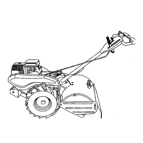
- Page 8 These symbols may appear on your Tiller or in literature supplied with the product. Learn and understand their meaning. FORWARD Rk"VER_E CAUTION Eh_INE FA._f CHOKE RJEL WARNIKG KNOW YOUR TILLER READ THIS OWNER'S MANUALAND SAFETY RULES BEFORE OPERATING YOUR TILLER. Compare the illustrationswith your tiller to familiarize yourself with the location of vari- ous controls and adjustments.
- Page 9 The operation of any tiller can result in foreign objects thrown into the eyes, which canresult in severe eye damage. Always wear safety glasses or eye shields before starting your tiller and while tilling. We recommend a wide vision safety mask over spectacles or standard safety glasses. HOW TO USE YOUR TILLER DEPTH STAKE Know how to operate all controls before...
- Page 10 CHECK ENGINE OIL LEVEL TURNING Release the dine control bar. • The engine in your unit has been • Move throttle control to "SLOW" posi- shipped, from the factory, already filled tion. with SAE 30 summer weight oil. • Place shift lever indicator in "I:" (forward) •...
- Page 11 NOTE: .Jfat a high altitude (3000 feet) or ,_CAUTION: Fill to _tthin 1/2 inch of top in cold temperatures (below 32°F), the car, of fuel tank to prevent dpills and to allow buretor fuel mixture may need to be for fuel expansion. If gasoline is acciden- adjusted for best engine performance.
- Page 12 • Do not lean on handle. This takes ADJUST WHEELS FOR CULTIVAT- weight off the wheels and reduces trac- tion. To get through a really tough sec- • Place blocks under dgl_thand side of tion of sod or hard ground, apply upward tiller and remove hairpln clip and clevis pressure on handle or lower the depth pin from dght hand wheel.
- Page 13 A,NTENA SCHEDULE . oU SE V, E /oo/ 7' Check Engine Oil Level Change Engine Oil I_1 _ Oil Pivot Points InspectSpark Arrestsr/ Muffler Inspect Air Screen Clean or Replace Air Cleaner Cartridge i_ 2 Clean Engine Cylinder Fins Replace Spark Plug I * (_mge rn_'e _ when _ng...
- Page 14 • Refill engine with oil. See =CHECK Disconnectsparkplugwire beforeper- formingany maintenance(exceptcarbure- ENGINE OIL LEVEL" in the Operation section of this manual. tor adjustment) to preventaccidentalstart- ing of engine. Prevent firesl Keep the engine free of grass, leaves, spilled oil, or fuel. Remove OII DrainPlug fuel from tank before tipping unit for main- tenance.
- Page 15 SPARK PLUG Muffler Replace spark plugs at the beginning of Blower each tilling season or after every 50 hou Housing of use, whichever comes first. Spark ph type and gap setting is shown in =PROD UCT SPECIFICATIONS" on page 4 of th manual.
- Page 16 • Place new belt in groove of transmis- TO REMOVE BELT GUARD sion pulley and into engine pulley. BELT NOTE: For ease of removal, remove hair- MUST BE IN GROOVE ON TOP OF pin clip and clevis pin from,left wheel. Pull IDLER PULLEY.
- Page 17 To maintain the superb tilling perfor- TINE REPLACEMENT ma_e of this machine the tines shoul_ ,_CAUTION: Tines are sharp. )Near be checked for sharpness, wear, and gloves or other protection when handling bending, particularly the tines which arq tines. next to the transmission. If the gap A badly worn tine causes your tiller to work between the tines exceeds 3-1/2 inche...
- Page 18 IDLE R PM A DJUSTMENT ENGINE • Rotate throttle hnkage counterolockwise Maintenance, repair, or replacement of the and hold against stop while adjusting emission control devices and systems, idle speed adjusting screw to obtain which are being done at the customers 1750 RPM.
- Page 19 NOTE: Fuel stabilizer is an acceptable Immediately prepare your tiller for storage alternative in minimizing the formation o at the end of the season or if the unit will fuel gum deposits during storage. _.dd., not be used for 30 days or more. bilizer to gasoline in fuel tank or storage _.CAUTION: Never store the tiller with...
- Page 20 PROBLEM CAUSE CORRECTION Will not sN_ 1. Out of fuel. 1. Fill fuel tank. 2. See "TO START ENGINE" in.the 2. Engine not "CHOKED" properly. Operation section. 3. Wait several minutes before 3. Engine flooded. attempting to start. 4. Dirty air cleaner, 4.
- Page 21 PROBLEM CORRECTIOk CAUSE Engine overheats 1. Low oil level/dirty oil. 1. Check oil level/change oil. 2. Clean engine:air screen. 2. Dirty engine air screen. 3, Dirty engine. 3. Clean cylinder fins, air screen, muf tier area. 4. Remove and clean muffler. 4.
- Page 22 TILLER - - MODEL NUMBER 91T.293202 HANDLES 30 \ PART PART DESCRIPTION DESCRIPTION STD533710 * Bolt, Cardage 3/8-16xl Gr.5 127012X ControlThrottle 109229X Lock, Handle 141406 Grip, Handle STD541437 * Nut, Centedock 3/8-16 110673X Grommet, Handle 19131611 Washer 13/32 x lx 11Ga. 127254X Bar, Drive ControlAssembly 109228X...
- Page 23 TILLER - - MODEL NUMBI=R 917.293202 MAINFRAME, L EFTSIDE PART PART DESCRIPTION DESCRIPTION 102190X "llm STD541431 * Nut, Kep_ Range 5/16-18 150750 STD551137 "Washer, Lock 3/8 795R "fireValve STD541037 *Nut, Hex 3/8-16 165710 Shield, Inner Belt Guard Rt 126875X Rivet;Drilled 154734 Screw Shift Lever STD624003...
- Page 24 TILLER -,- MODEL NUMBER 917.293202 MAINFRAME, RIGHT SIDE PART PART DESCRIPTION DESCRIPTION 10_190X Tire STD541431 * Nut, Keps 5/16-18 150750 102332X Bracket,Reinforcment 795R Tire Valve 74760524 Bolt,Hex 5/16-18x1-1/2 102173X CounterWeight, R.H..Engine, (See Breakdown) Briggs& StrattonModei No. STD551137 * Washer, Lock 3/8 137202,Type No.
- Page 25 TILLER - - MODEL NUMBER 917.293202 TRANSMISSION PART PART DESCRIPTION DESCRIPTION 165728 TransmissionAssembly(Includes 102134X Chain #35-50 Pitch Key Nos. 2-54) 150737 Ground Shaft Assembiy 165729 Gearcase, LH. w/Besring 143008 Bearing, Shaft,Ground Drive (Includes Key No. 4) 106388X Spacer 0.70 x 1.00 x 1.150 161963 Gasket, Gearcase 102121X...
- Page 26 TILLER - - MODEL NUMBER 917.293202 TINE SHIELD PART PART DESCRIPTION DESCRIPTION Nut, Keps Hex 1/4-20 98000129 Nut, Flange 5/16-18 STD541425 161415X558 Shield,Side, Outer L H, STD532512 Bolt, Cardage 1/4-20 x 1-1/4 8393J Pin, Stake, Depth 102701X Grip 12000036 Ring, KUp STD541037 Nut, Hex 3_-16 STD533107...
- Page 27 TILLER - - MODEL NUMBER 917.293202 TINE ASSEMBLY PART PART DESCRIPTION DESCRIPTION 4459J "line, Outer, LH. 74610616 Bolt, Hex 3/8-24 x 1 132673 Pin, Shear 4460J "Rne,Outer, R.H. 6554J "Rne, Inner, LH. 132728 Assernb4y, Hub and Plate, R.H. 163552 Retainer, SpringZinc 6555J "Rne,Inner, R.H.
- Page 28 137538 Deoal, Caution, Drive Control 120431X Decal, Hand Ptacement 1nc_180X Decal, Shift Indicator 110719X Decal, Operation and Lubrication 165268 Decal, Craftsman 120075X Decal, Warning, Rotatinglines 157984 Decal, Counter RoL "llne 165278 Decal, 5 HP 162215 Decal, Tree Shield Wing Dora...
- Page 29 TILLER - - MODEL NUMBER 917.293202 I_NGINE, BRIGGS & STRA'I-rON - - MODEL NUMBER 137202, TYPE NO. 1125-Et...
- Page 30 TILLER - - MODEL NUMBER 917.293202 ENGINE,BRIGGS& STRATTON - - MODELI_UMBER137202,TYPE NO. 1125-E1 t222 162( 1110...
- Page 31 _.o,.E, oR,oos. STRATTO..O0_'.UMO_.._202, TYP_.O. 1,2_,...
- Page 32 TILLER - - MODEL NUMBER 917.293202 ENGINE, BRIGGS & STRATTON - - MODEL NUMBER 137202, TYPE NO. 1125-E1 PART PARr DESCRIPTION DESCRIPTION 497144 CylinderAseambly 93312 Retainer, Intake Valve and 399268 Bushing,Cylinder Exhaust Spdng 299819 * Seal, Oil 260642 Tappet,Valve 214040 Head, Cylinder 214726 Gear, Cam...
- Page 33 TILLER - - MODEL NUMBER 917.293202 ENGINE,BRIGGS& STRATTON- - MODELNUMBER137202,TYPE NO.1125-E1 PART PART DESCRIPTION DESCRIPTION 280720 BullCrank 231550 Tube, Breather 231520 Screw, Shoulder 67838 Grommet, BreatherTube 262279 Rod, Speed Control 491435 Filter,Air 262284 Spdng, Govemor 494279 Cleaner, Air 262270 Link,Throttle 94897 Screw 262359...
- Page 36 For in-home major brand repair service: Call 24 hours a day, 7 days a week 1-800-4-MY-HOME sM (1-800-469-4663) Para pedir servicio de reparaci6n a domicilio 1-800-676-5811 In Canada for all your service and parts needs call Au Canada pour tout le service ou les pi_ces 1-800-665-4455 For the repair or replacement parts you need: -Call 6 am-11pm CST, 7 days a week...