Table of Contents
Advertisement
Quick Links
Owner's Manual
IC..FTSMeWl
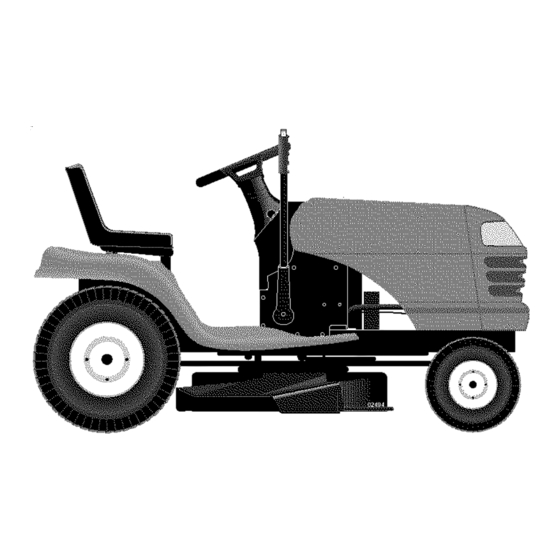
LAWN TRACTOR
17.0 HP, 42" Mower
Electric Start
Automatic Transmission
Model No.
917.273140
[_
This product has a low emission engine which operates
differently from previously built engines. Before you start the
engine, read and understand this Owner's Manual.
IMPORTANT:
Read and follow all Safety
Rules and Instructions
before
operating
this equipment.
For answers to your questions
about this product, Call:
1-800-659-5917
Sears Craftsman Help Line
5 am - 5 pm, Mon - Sat
Sears, Roebuck and Co., Hoffman Estates, IL 60179 U.S.A
Visit our Craftsman website:www.sears.com/craftsman
Advertisement
Table of Contents

Related Manuals for Craftsman 917.273140


Summary of Contents for Craftsman 917.273140
- Page 1 Read and follow all Safety about this product, Call: Rules and Instructions before 1-800-659-5917 Sears Craftsman Help Line operating this equipment. 5 am - 5 pm, Mon - Sat Sears, Roebuck and Co., Hoffman Estates, IL 60179 U.S.A Visit our Craftsman website:www.sears.com/craftsman...
- Page 2 IN HOME warranty service will still be available after the first 30 days of pur- chase, but a trip charge will apply. This charge will be waived if the Craftsman product is dropped off at an authorized Sears location. For the nearest authorized Sears location, please call 1-800-4-MY-HOME®.
- Page 3 IMPORTANT: This cutting machine is capable of amputating hands and feet and throw- ing objects. Failure to observe the following safety instructions could result in serious injury or death. • Do not mow in reverse unless abso- _WARNING: In order to prevent ac- lutely necessary.
- Page 4 • Never carry children. They may fall off • Mow up and down slopes, not across. and be seriously injured or interfere with • Remove obstacles such as rocks, tree safe machine operation. limbs, etc. • Never allow children to operate the •...
- Page 5 • Remove obstacles such as rocks, tree • Be sure the area is clear of other people limbs, etc. before mowing. Stop machine if anyone enters the area. • Watch for holes, ruts, or bumps. Uneven terrain could overturn the machine. Tall •...
- Page 6 AGREEMENTS Oil Capacity: W/Filter 4.0 Pints W/O Filter 3.75 Pints Congratulations on making a smart pur- chase. Your new Craftsman® product is Spark Plug: Champion RC12YC designed and manufactured for years of (GAP: .040") dependable operation. But like all prod-...
- Page 7 Steering Wheel Steering Wheel Insert (1) Large Flat Washer 1/2-20 (1) Hex Bolt (1) Locknut 1/4-28 x 1-1/4 (1) Locknut 1/4-28 Steer, Steering Extension Boot Wheel Adapter Shaft teering (_Washer 17/32 x 1-3/16 x 12 Gauge _(1) Knob For Future Use Keys Slope Sheet Video Cassette...
- Page 8 Your new tractor has been assembled at the factory with the exception of those parts left unassembled for shipping purposes. To ensure safe and proper operation of your tractor all parts and hardware you assemble must be tightened securely. Use the correct tools as necessary to insure proper tightness.
- Page 9 3. Place seat on seat pan so head of NOTE: You may now roll or drive your shoulder bolts are positioned over the tractor off the skid. Follow the appropriate large slotted holes in pan. instruction below to remove the tractor 4.
- Page 10 CHECK BRAKE SYSTEM INSTALL MULCHER PLATE After you learn how to operate your trac- (If previously removed) tor, check to see that the brake is properly 1. Raise and hold deflector shield in adjusted. See "TO ADJUST BRAKE" in upright position. the Service and Adjustments section of 2.
- Page 11 These symbols may appear on your tractor or in literature supplied with the product. Learn and understand their meaning. I'.,I REVERSE NEUTRAL HIGH CHOKE FAST SLOW IGNITION ENGINE OFF LIGHTS ON ENGINE ON ENGINE START PARKING BRAKE PARKING BRAKE PARKING BRAKE LOCKED UNLOCKED...
- Page 12 KNOW YOUR TRACTOR READ THIS OWNER'S MANUAL AND SAFETY RULES BEFORE OPERATING YOUR TRACTOR Compare the illustrations with your tractor to familiarize yourself with the locations of various controls and adjustments. Save this manual for future reference. Light Switch Ignition Switch Attachment Clutch Lever Lift Lever...
- Page 13 The operation of any tractor can result in foreign objects thrown into the eyes, which can result in severe eye damage. Always wear safety glasses or eye shields while operating your tractor or performing any adjustments or repairs. We recommend standard safety glasses or a wide vision safetyl mask worn over spectacles.
- Page 14 TO ADJUST GAUGE WHEELS TO OPERATE ON HILLS Gauge wheels are properly adjusted _iLWARNING: Do not drive up or down when they are slightly off the ground when hills with slopes greater than 15° and do mower is at the desired cutting height in not drive across any slope.
- Page 15 TOWING CARTS AND OTHER ATTACH- Use fresh fuel next season. See Storage MENTS Instructions for additional information. Never use engine or carburetor cleaner Tow only the attachments that are recom- products in the fuel tank or permanent mended by and comply with specifications damage may occur.
- Page 16 AUTOMATIC TRANSMISSIONWARM UP NOTE: During this step there will be no movement of drive wheels. The air is being Beforedrivingthe unit in cold weather, removed from hydraulic drive system. the transmissionshould be warmed up as 5. Move motion control lever to neutral follows: (N) position.
- Page 17 MOWING TIPS MULCHING MOWING TIPS • Mower should be properly leveled for IMPORTANT: For best performance, keep best mowing performance. See "TO mower housing free of built-up grass and LEVEL MOWER HOUSING" in the trash. Clean after each use. Service and Adjustments section of this •...
- Page 18 MAINTENANCE SCHEDULE ,_,_-_ ,_,_ _ d_. ,_ AS YOU COMPLETE DATES REGULAR SERVICE f___SERVlC Check Brake Operation Check Tire Pressure Check Operator Presence Interlock Systems Check for Loose Fasteners Sharpen/Replace Mower Blades Lubrication Chart Check Battery Level Clean Battery and Terminals Check Transaxle Cooling...
- Page 19 TRACTOR 4. Reassemble blade bolt, lock washer and flat washer in exact order as Always observe safety rules when per- shown. forming any maintenance. 5. Tighten blade bolt securely (27-35 Ft. BRAKE OPERATION Lbs. torque). If tractor requires more than six (6) feet IMPORTANT: Blade bolt is grade 8 heat stopping distance at high speed in highest...
- Page 20 NOTE: The original equipment battery on SAE VISCOSITY GRADES your tractor is maintenance free. Do not attempt to open or remove caps or covers. Adding or checking level of electrolyte is not necessary. TEMPERATURE RANGE ANTiCiPATED BEFORE NEXT OIL CHANGE TO CLEAN BATTERY AND TERMINALS Change the oil after every 50 hours of op- Corrosion and dirt on the battery and...
- Page 21 AIR FILTER CLEAN AIR INTAKE/COOLING AREAS Your engine will not run properly using a To insure proper cooling, make sure the dirty air filter. Clean the foam pre-cleaner grass screen, cooling fins, and other exter- after every 25 hours of operation or every nal surfaces of the engine are kept clean at all times.
- Page 22 ARNING: TO AVOID SERIOUS INJURY, BEFORE PERFORMING ANY SER- VICE OR ADJUSTMENTS: 1. Depress clutch/brake pedal fully and set parking brake. 2. Place motion control lever in neutral (N) position. 3. Place attachment clutch in "DISENGAGED" position. 4. Turn ignition key to "STOP" and remove key. 5.
- Page 23 • When distance "D" is 1/8" to 1/2" lower TO LEVEL MOWER HOUSING at front than rear, tighten nuts "F" against Adjust the mower while tractor is parked trunnion on both front links. on level ground or driveway. Make sure •...
- Page 24 Mandrel Idler Pulleys Road test tractor for proper stopping distance as stated above. Readjust if necessary. If stopping distance is still greater than five (5) feet in highest gear, further maintenance is neces- sary. Replace brake pads or contact a Sears or other qualified service center.
-
Page 25: Transaxle Motion Control Lever Neutral Adjustment
TRANSAXLE MOTION CONTROL FRONT WHEEL TOE-IN/CAMBER LEVER NEUTRAL ADJUSTMENT The front wheel toe-in and camber are not The motion control lever has been preset adjustable on your tractor. If damage has occurred to affect the front wheel toe-in or at the factory and adjustment should not be necessary. - Page 26 3. Connectthe other end of the BLACK TO REPLACE HEADLIGHT BULB cable (D) to good chassisground, 1. Raise hood. awayfrom fuel tank and battery. 2. Pull bulb holder out of the hole in the backside of the grill. TO REMOVECABLES,REVERSE ORDER - 3.
- Page 27 ENGINE Start engine and allow to warm for five minutes. Make adjustments with engine Maintenance, repair, or replacement running and shifVmotion control lever the emission control devices and systems, in neutral (N) position. which are being done at the customers ex- Idle speed setting - With throttle...
- Page 28 Immediately prepare your tractor for stor- Also, alcohol blended fuels (called gasohol age at the end of the season or if the trac- or using ethanol or methanol) can attract moisture which leads to separation and will not be used for 30 days or more. WARNING: Never store the tractor formation of acids during storage.
- Page 29 TROUBLESHOOTING CHART: See appropriate section in manual unless directed to Sears service center PROBLEM CAUSE CORRECTION Will not start Out of fuel. 1. Fill fuel tank. 2. See "TO START ENGINE" in Engine not "CHOKED" properly. Operation section. 3. Wait several minutes before Engine flooded.
- Page 30 TROUBLESHOOTING CHART: See appropriate section in manual unless directed to Sears service center PROBLEM CAUSE CORRECTION Loss of power 1. Cutting too much grass/too 1. Set in "Higher Cut" position/ fast. reduce speed. 2. Throttle in "CHOKE" position. 2. Adjust throttle control. 3.
- Page 31 TROUBLESHOOTING CHART: See appropriate section in manual unless directed to Sears service center PROBLEM CAUSE CORRECTION Mower blades will 1. Obstruction in clutch 1. Remove obstruction. mechanism. not rotate 2. Worn/damaged mower drive 2. Replace mower drive belt. belt. 3. Frozen idler pulley. 3.
- Page 32 SERVICE NOTES...
- Page 33 TRACTOR - - MODEL NUMBER 917.273140 SCHEMATIC BATTERY SOLENOID FUSE STARTER _3LACK • CLUTCH / BRAKE (PEDAL UP) LINE (CLUTCH OFF) GREEN I 85 86 I FUEL SHUT-OFF SOLENOID SEAT SWITCH _30/] (_FSO EQUIPPED) (NOT OCCUPIED) BL_CK PRESENCE RELAY #1 i 85 86 I BLACK...
- Page 34 TRACTOR - - MODEL NUMBER 917.273140 ELECTRICAL...
- Page 35 TRACTOR - - MODEL NUMBER 917.273140 ELECTRICAL PART DESCRIPTION 163465 Battery 74760412 Bolt, Hex Head 1/4-20 Unc x 3/4 176689 Box Batt.ery Fender 176137 Switch, Interlock 183759 Harness, Light Socket (Includes 4152J) 4152J Bulb, Light 4799J Cable, Battery, 6 Gauge, Red, 11" 146147 Cable, Battery, 6 Gauge, Red, W/16 Wire 175158...
- Page 36 TRACTOR - - MODEL NUMBER 917.273140 CHASSIS AND ENCLOSURES ,145...
- Page 37 TRACTOR - - MODEL NUMBER 917.273140 CHASSIS AND ENCLOSURES PART DESCRIPTION 174619 Chassis Stamping 176554 Drawbar 17060612 Screw 3/8-16 x 3/4 155272 Bumper Hood/Dash 168337X013 Dash STD533710 Bolt, Carriage 3/8-16 x 1 174996 Panel, Dash, LH. 172105X010 Panel, Dash, R.H. 17490608 Screw Thdrol 3/8-16 x 1/2 185682X613 Hood Assembly...
- Page 38 TRACTOR - - MODEL NUMBER 917.273140 GROUND DRIVE _103...
- Page 39 TRACTOR - - MODEL NUMBER 917.273140 GROUND DRIVE PART PART DESCRIPTION DESCRIPTION Transaxle (See Breakdown) 134683 Keeper Belt Engine Hydro Gr 314-0510 169183 Strap Torque Lh Hydro 169182 Strap Torque Rh Hydro 165866 Rod Shift Fender Adjust STD561210 Pin Cotter 1/8 x 1 CAD 137057 Spacer 121749X...
- Page 40 TRACTOR - - MODEL NUMBER 917.273140 STEERING ASSEMBLY j_"----42 37-_...
- Page 41 TRACTOR - - MODEL NUMBER 917.273140 STEERING ASSEMBLY KEY PART DESCRIPTION 184704X428 Steering Wheel 172393 Axle Assembly 169840 Spindle Assembly, LH. 169839 Spindle Assembly, R.H. 6266H Bearing, Race, Thrust, Hardened 121748X Washer 25/32 x 1-5/8 x 16 Ga. 12000029 Ring, Klip 175121 Draglink STD551137...
- Page 42 TRACTOR - - MODEL NUMBER 917.273140 ENGINE OPTIONAL EQUIPMENT Spark Arrester PART PART DESCRIPTION DESCRIPTION Line, Fuel 170548X505 Control, Throttle 137040 Plug, Drain Oil Easy 17720408 Screw, Hex Head, Thread Cutting 181654 Bushing Snap 1/4-20 x 5/8 124028X Screw, Hex Washer Head, Thd., Engine, (See Breakdown) Kohler 17670412 Roll.
- Page 43 TRACTOR - - MODEL NUMBER 917.273140 SEAT ASSEMBLY \\\\ KEY PART PART DESCRIPTION DESCRIPTION 180597 Seat 121248X Bushing, Snap 180166 Bracket, Pivot, Fender 72050412 Bolt, Carriage 1/4-20 x 1-1/2 71110616 Bolt 134300 Spacer, Split .28 x .88 19131610 Washer 13/32 x 1 x 10 Ga. 121250X Spring 1450O6...
- Page 44 Decal, Hood Side 149516 Decal, Battery Dngr/Psn Eng 172331 Decal, Deck 138311 Decal, Lift Handle 186282 Pad Footrest LH STLT Decal, Fender, Craftsman 165800X428 156439 Pad Footrest RH STLT Decal, Fender Danger 165799X428 179128 Decal, Deck"B"42" 169210 Decal By Pass LT Hydro...
- Page 45 TRACTOR - - MODEL NUMBER 917.273140 LIFT ASSEMBLY 32 / KEY PART KEY PART DESCRIPTION DESCRIPTION 159460 Link, Front Lift Lever Inner Wire Assembly 173288 159471 Shaft Assembly, Lift 73350800 Nut, Hex, Jam 1/2-13 Unc 105767X Trunnion Pin, Groove 175689 120OO0O2 E-Ring 73800800...
-
Page 46: Mower Deck Parts List
TRACTOR - - MODEL NUMBER 917.273140 MOWER DECK 106"_ f103 f]//,_, _o_J,/_ to4"_:/ F/ II t03f \ /;f t01J_ 104 t06 t02 f _t16 .1t2 115 4 9---"... - Page 47 TRACTOR - - MODEL NUMBER 917.273140 MOWERDECK PART PART DESCRIPTION DESCRIPTION 165892 Mower Deck Assembly, 42" 165723 Spacer, Retainer STD533107 Bolt 141043 Guard, TUV Idler 138017 Bracket Assembly, Sway Bar, 1849396 Knob Custom Oval Front 144959 V-Belt 165460 Bracket Sway Bar 38/42" eck 73800600 Nut Lock Hex w/Ins.
- Page 48 122- _128 Z r- -" ",,1 _127...
- Page 49 TRACTOR-- MODEL NUMBER 917.273140 HYDRO GEAR TRANSAXLE - - MODEL NUMBER 314-0510 PART PART DESCRIPTION DESCRIPTION Rotor, Brake 170351 Main Housing, Assembly 170408 Brake Puck 170352 Side Housing, Assembly 142883 Puck Plate 170353 Center Section, Assembly 142882 170354 Swashplate, Trunion 142887 Brake Actuating Pin Machined...
- Page 50 TRACTOR - - MODEL NUMBER 917.273140 KOHLER ENGINE-MODEL NUMBER CV490,TYPE NUMBER 27508 CYLINDER HEAD, VALVE AND BREATHERJ CRANKCASEJ 22 22...
- Page 51 TRACTOR-- MODEL NUMBER 917.273140 KOHLER ENGINE-MODEL NUMBER CV490,TYPE NUMBER 27508 CYLINDER HEAD/VALVE/BREATHER CRANKCASE PART DESCRIPTION PART DESCRIPTION 25-351-01 -S Lifter, valve (2) 12-755-94-S Kit, cylinder head (Includes 12-032-03-S Seal, crankshaft 3-17, Gaskets 12 041 01-S Block, cylinder (Qty. 2), 12 041 02-S, & 12 Use Short Block 12 522 51) 12-445-02-S 041 03-S)
- Page 52 TRACTOR-- MODEL NUMBER 917.273140 KOHLER ENGINE-MODEL NUMBER CV490,TYPE NUMBER 27508 IGNITION/ELECTRICAL BLOWER HOUSING AND BAFFLES] '18_, AiR iNTAKE 1°L...
- Page 53 TRACTOR - - MODEL NUMBER 917.273140 KOHLER ENGINE-MODEL NUMBER CV490,TYPE NUMBER 27508 & BAFFLES BLOWER HOUSING IGNITION/ELECTRICAL PART PART DESCRIPTION DESCRIPTION 12-086-14-S M-545010-S Screw, hex. flange Screw, hex. flange M10x1.5x46 M5x0.8xl 0 (6) 12-468-03-S 24-468-10-S Washer, plain 1/4" Washer, plain 3/8" 24-162-03-S Screen, grass 12-146-07-S...
- Page 54 TRACTOR - - MODEL NUMBER 917.273140 KOHLER ENGINE-MODEL NUMBER CV490,TYPE NUMBER 27508 STARTING SYSTEM • OIL PAN t LUBRICATION...
- Page 55 TRACTOR - - MODEL NUMBER 917.273140 KOHLER ENGINE-MODEL NUMBER CV490, TYPE NUMBER 27508 STARTING SYSTEM ENGINE CONTROLS PART PART DESCRIPTION DESCRIPTION 12-079-11-S M-839070-S Screw, hex. flange Linkage, choke 12-237-01-S M8x1.25x70 (2) Clamp, cable 24-086-43-S 25-098-07-S Starter assembly (Includes Screw, hex. flange M-664020-S Screw, lobed socket 3-8)
- Page 56 TRACTOR-- MODEL NUMBER 917.273140 KOHLER ENGINE-MODEL NUMBER CV490,TYPE NUMBER 27508 EXHAUST CRANKSHAFT] FUEL SYSTEM]...
- Page 57 TRACTOR-- MODEL NUMBER 917.273140 KOHLER ENGINE-MODEL NUMBER CV490,TYPE NUMBER 27508 FUEL SYSTEM CRANKSHAFT PART PART DESCRIPTION DESCRIPTION 12-014-57-S M-641060-S Crankshaft (Includes 2) Nut, hex. flange M6xl .O(2) 25-139-27-S M-629116-S Stud M6xl .Oxl 16 (2) Plug, cup 12-853-118-S Kit, carburetor w/gasket (Includes 4,5,6 qty 1 EXHAUST Tie, cable 12-454-03-S,...
- Page 58 SERVICE NOTES...
- Page 59 SUGGESTED GUIDE FOR SIGHTING SLOPES FOR SAFE OPERATION ¢.o down the face of slopes, never across the face. Do not mow ARNING: To avoid serious injury, operate your tractor up and slopes greater than 15 degrees. Make turns gradually to prevent tipping or loss of control.
- Page 60 Get it fixed, at your home or ours! Your Home For repair - in your home - of all major brand apphances, lawn and garden equipment, or heating and coohng systems, no matter who made it, no matter who sold it! For the replacement parts, accessones owner's manuals that you need to do-it-yourself.