
Related Manuals for Craftsman C950524302A


Summary of Contents for Craftsman C950524302A
- Page 1 8 _ JR8 owner's manual DUAL STAGE Model SNOW BLOWER C950524302A 9.5 H.P. 27 inch CAUTION: You must read and understand this owner's manual before operating unit. Serial No. 401357 SEARS CANADA INC., TORONTO, ONTARIO M5B 2B8 Printed in U.S.A.
-
Page 2: Hazard Symbolsand The Meanings
RULES FOR SAFE OPERATION GeneralInformation Hazard Symbolsand the meanings Thisinstruction book iswritten fur a person with somemechanical ability. Thesesymbols areused onyour equipment anddefined inyour operating Ukemost s en_ice b ooks, notallthesteps aredescribod. Steps onhow to manual. R eview andunderstand themeanings. Theuseofoneofthese loosen ortighten f asteners arestepsanyone canfollowwith some symbols c ombined with a signal w ord willalert youtopotential hazards mechanical ability. -
Page 3: Operatingsymbols And Their Meanings
RULES FOR SAFE OPERATION OperatingSymbols and their meanings These symbolsare usedon yourequipmentanddefinedin youroperating _IL DANGER manual It is important t hatyoureviewand understand the meanings. Failureto understand the symbolsmightresultin harmto you. • Neverattempt toclear auger ofdebris ordogged snowwhile equipment is engaged orengine isrunning. Clogged orbfscked a ugers store energy andcanrotateunexpe_:tedly, EVEN WITHENGINE OFR Fuel... - Page 4 RULES FOR SAFE OPERATION AWARNING _kDANGER WHEN ADDING FUEL • Turn engine OFF andlet engine cool a t least2 minutes b efore removing • Beawareofyourenvironment whileoperating e quipment. Running over gascap. items such as graveldoormats, newspapers, toys, a ndrocks hidden •Fm fualtankoutdoors o rIn weU-ventilatad area.
-
Page 5: Owner's Information
3. Tire replacement or repair caused by puncturesfrom outside objects, such as nails, thorns, stumps or glass. 4. In home service. Warranty service is available by returningthe Craftsman snow blower to the nearest Sears Service Centre/Department in Canada. This warranty applies only while this product is in use in Canada. -
Page 6: Table Of Contents
TABLE OF CONTENTS HAZARD SYMBOLS AND THE MEANINGS ..HOW TO USE THE CLEAN-OUT TOOL ... OPERATING SYMBOLS AND THEIR MEANINGS ..OPERATING TIPS ......OWNER'S INFORMATION ......SERVICE RECOMMENDATIONS ....ASSEMBLY ........CUSTOMER RESPONSIBILITIES ....TOOLS REQUIRED FOR ASSEMBLY ....SNOW BLOWER ....... -
Page 7: Assembly
ASSEMBLY TOOLS REQUIRED FOR ASSEMBLY CONTENTS OF SHIPPING CARTON 1 - Knife 1- Snow Slower 2 - 1/2" wrenches (or adjustable wrenches) 1- Container of Fuel Stabilizer 2 - 9/16" wrenches (or adjustable wrenches) 1- Snow Chute Assembly 2 - 3/4" wrenches (or adjustable wrenches) 1- Crank Assembly 1 - 3/8"... -
Page 8: Unpacking
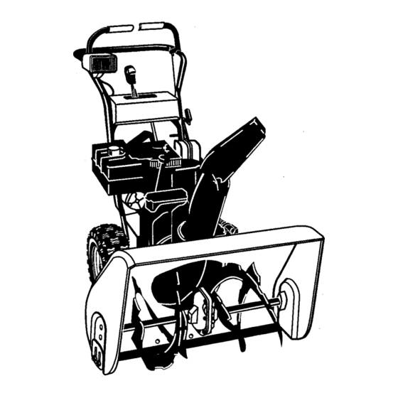
ASSEMBLY Figure 1 shows the snow blower in the shipping position. Figure 2 shows the snow blower completely assembled. Reference to right and left hand side of the snow blower is from the operator's position at the handle. UNPACKING Locate the two tear tabs at the bottom of the carton. Figure 1 Traction Ddve AugerDr_e... -
Page 9: Upper Handle And Crank Assembly
ASSEMBLY UPPER HANDLE AND CRANK ASSEMBLY Loosen, but do not remove the screws, flatw'ashers, lock- Bolt washers and hex nuts in the upper holes of the lowerhan- Lockwasher dle. Locknut Remove the fasteners and the crank assembly eyebolt from the lower holes of the lower handle. Raise upper handle into operating position. -
Page 10: Speed Select Lever
ASSEMBLY SPEED SELECT LEVER 1. Cut plastic tie securing speed select lever assembly to the shifter bracket. (See Figure 7) Remove Iocknut, washer, spring, and the bolt, (See Figure 9) Control Panel Position speed selector lever assembly as shown in Figure 8. -
Page 11: Snow Chute Assembly
ASSEMBLY SNOW CHUTE ASSEMBLY HEADLIGHT ASSEMBLY Position the snow chute onto the snow chute flange. Al- The headlight is mounted on the right side of the upper ign the three holes in the snow chute with holes in snow handle. It is installed upside-down for shipping purposes. chute flange. -
Page 12: Engine And Snow Blower Overview
OPERATION Get to know your snow blower and its controls. Be sure you (or any other operator) have read and understood the Operation Precautions listed on page 2 of this manual. Choke Gas Tank Auger Drive Traction Drive Control Clutch Lever Clutch Lever Primer Button Traction Drive... -
Page 13: Snow Blower Operation
OPERATION The operation of any snow blower can result in foreign objects being thrown into the eyes,which can result in severe eye damage. Always wear safety glasses or eye shields before beginning snow blower Operation. We recommend standard safety glasses or Wide Vision Safety Mask for over spectacles. SNOW BLOWER OPERATION ARNING: Read Owner's Manual before oper- ating machine. -
Page 14: Wheel Lock Out Pin
OPERATION WHEEL LOCK OUT PIN 1. The right wheel is securedto the axle witha klick pin. This unit was shipped with this klick pin in the locked position. (Figure 15). For ease of maneuverability when lighter conditions pre- vail, remove klick pin from wheel locked position and in- sert into single... -
Page 15: Before Starting Engine
OPERATION BEFORE STARTING ENGINE Fill the fuel tank with fresh, clean, unleaded regular, un- leaded premium, or reformulated automotive gasoline Check the oil with a minimum of 85 octane along with a fuel stabilizer (follow instructions on fuel stabilizer package). DO NOT NOTE: The engine was shipped from the factory filled use leaded gasoline. -
Page 16: Before Stopping The Engine
OPERATION BEFORE STOPPING THE ENGINE Run the engine for a few minutes to helpdry off any moisture on the engine. TO STOP ENGINE CAUTION: To stop the engine, do not move the choke Pull out the safety key. control to CHOKE position. Backfire or engine damage can occur. - Page 17 OPERATION Choke Knob Primer Safety Key Starter Motor Recoil Starter Handle Stop Switch Figure 20 How To Start A Cold Engine If the engine does not start in 5 or 6 tries, See Difficult Be sure auger drive and traction drive lovers are in the Starting in the 'q'roubleshooting Table".
-
Page 18: Frozen Starter
OPERATION FROZEN STARTER closed, poorly ventilated areas. Engine exhaust WARNING: Never run engine indoors or in en- If the starter is frozen and will not turn engine: contains CARBON MONOXIDE, AN ODORLESS Pull as much rope out of the starter as possible. AND DEADLY GAS. -
Page 19: Operating Tips
OPERATION OPERATING TIPS Most efficient snowblowingis accomplished when snow After the snowblowing job has been completed, allow the is removed immediately after it falls. engine to idle far a few minutes, to melt snow and ice ac- cumulated on the engine. For complete snow removal, slightly overlap each swath previously taken. -
Page 20: Service Recommendations
SERVICE RECOMMENDATIONS SERVICE RECOMMENDATIONS RRST BEFORE EVERY EVERY EVERY EVERY EVERY BEGINNING PROCEDURE EACH EACH BEFORE HOUR HOURS HOURS HOURS HOURS HOURS SEASON STORAGE Tighten all screws and nuts Check TractionClutch Cable Ad ustment (See Cab e Ad ustment) ; _l Check Auger clutch Cable Ad ustment "_... -
Page 21: Customer Responsibilities
CUSTOMER RESPONSIBILITIES Some adjustments will need to be made periodically to properly maintain your snow blower. All adjustments in ADJUSTMENTS/REPAIRS section of this manual should be checked at least once each season. SNOW BLOWER The following adjustment should be performed more than once each season. -
Page 22: Lubrication - Every 25 Hours
CUSTOMER RESPONSIBILITIES LUBRICATION - EVERY 25 HOURS Chute Rotation Gear Lubricate the chute rotation gear with automotive type oil. (see Figure 24). Figure 24 Chains Lubricatethe chains w_tha chain type lubricant. Wipe the hexahaft and sprockets With 5W30 motor oil. 1. -
Page 23: Engine
CUSTOMER RESPONSIBILITIES ENGINE TEMPERATURE TYPE OF OIL 0°F (-18 ° C) and above S.A.E. 5W30 POWER RATINGS 0°F (-18 ° C) and below synthetic 5W30 The power ratings for an individualengine model are initially developed by starting with SAE (Society of Automotive SAE VlSCosrrY GRADES Engineers) code J1940 (Small Engine Power &... -
Page 24: Adjustment/Repair
ADJUSTMENT/REPAIR To adjust skids, proceed as follows: 4_lb WARNING: Always turn unit off, remove igni- tion key and disconnect the spark plug wire be- Place a block (equal to height from ground desired) un- fore making any repairs or adjustments. der scraper bar near but not under skid. -
Page 25: How To Remove The Snow Hood
ADJUSTMENT/REPAIR HOW TO REMOVE THE SNOW HOOD Mounting Screws To access the spark plug, the snow hood must be removed Snow Hood as follows: Remove the choke control knob (see Figure 29). Spark Plug Remove the safety key. Remove the mounting screws (see Figure 30). Slowly remove the snow hood. -
Page 26: Belt Adjustment
ADJUSTMENT/REPAIR BELT ADJUSTMENT Traction Drive Belt The traction drive belt has constant spring pressure and does not require an adjustment. If the traction drive belt is slipping, replace the belt. See "How To Replace The Belts" in the Maintenance section. Auger Drive Belt If your snowthrower will not discharge snow, check the control cable adjustment. -
Page 27: How To Replace The Belts
ADJUSTMENT/REPAIR HOW TO REPLACE THE BELTS The drive belts are of special construction and must be 16. Install the belt cover. Tighten screw (See Figure 33). replaced with original factory replacement belts available 17. Check the adjustmentof the cables.See "How To Check from your nearest authorized service center. - Page 28 ADJUSTMENT/REPAIR Belt Guide Auger Drive Pulley Auger Drive Belt Traction Drive Spring Traction Drive Belt Traction Drive Pulley Swing Plate Axle Red Engine Pulley Figure 37...
- Page 29 ADJUSTMENT/REPAIR How To Remove the Traction Drive Belt If the snow thrower will not move forward, check the traction 11. Install and adjust the auger drive belt. See "How To Re- drive belt for wear or damage. If the traction drive belt is worn move The Auger Drive Belt"...
-
Page 30: Belt Guide Adjustment
ADJUSTMENT/REPAIR BELT GUIDE ADJUSTMENT 1. Remove spark plug wire. Have someone engage auger drive. Belt Guide Measure the distance between the belt guide and belt. The distance should be 1/8 inch (3.175 mm) for guide. See Figure 39. If adjustment is necessary, loosen belt guide mounting bolt. -
Page 31: Traction Drive Cable Adjustment
ADJUSTMENT/REPAIR Traction Drive Cable Adjustment Bolt Boffom Panel WARNING: Drain the gasoline outdoors, away from fire or flame. Remove the gas from the gas tank. Stand the snow Auger Housing thrower up on the front end of the auger housing. Loosen the bolts on each side of the bottom panel (see Figure 42). -
Page 32: How To Adjust Or Replace The Friction Wheel
ADJUSTMENT/REPAIR HOW TO ADJUST OR REPLACE 5. Tighten the jam nut. THE FRICTION WHEEL Install the bottom panel (see Figure 45). How To Check The Friction Wheel If the snow thrower will not move forward, check the traction Tighten the bolts on each side of the bottom panel. drive belt, the traction drive cable or the friction wheel. - Page 33 ADJUSTMENT/REPAIR How To Replace The Friction Wheel If the frictionwheel is worn or damaged, Me snow thrower will not move forward. The friction wheel must be replaced as follows. 1. Remove the gas from the gas tank. Stand the snow thrower up on the front end of the auger housing (4).
- Page 34 ADJUSTMENT/REPAIR 10. Remove the three fasteners that holdthe friction wheel to the hub (see Figure 51). 11. Remove the friction wheel from the hub. Slip the fric- tion wheel off the hex shaft. 12. Assemble the new friction wheel ontohub withthe fas- teners removed earlier.
-
Page 35: Auger Shear Bolt Replacement
ADJUSTMENT/REPAIR AUGER SHEAR BOLT REPLACEMENT The augers are securedto the auger shaft with special bolts NOTE: For the operator's convlence, the shear bolt that are designed to break if an object becomes lodged in the wrenches are located in the toolbox. auger housing. -
Page 36: Storage
STORAGE OFF SEASON STORAGE Thoroughly clean the snow blower. ARNING: Never store engine with fuel in tank indoors or In enclosed, poorly ventilated enclo- Lubricate all lubrication points (see Lubrication, see Cus- sures, where fuel fumes may reach an open tomer Responsibilities). -
Page 37: Trouble Shooting Chart
TROUBLE SHOOTING CHART PROBLEM LOOK FOR REMEDY Difficult starting Defective spark plug. Replace defective spark plug. Engine runs erratically Blocked fuel line. Clean fuel line. Empty gas tank. Check fuel supply, Stale gasoline. Add fresh gasoline. Water or dirt in fuel system. Remove carburetor bowl to drain fuel tank. -
Page 38: Repair Parts
REPAIR PARTS CRAFTSMAN 27" SNOW BLOWER C950524302A PIECESDERECHANGE CRAFTSMAN 27" CHASSE NEIGE C950524302A ENGINE / MOTEUR 25-2 25-3 25-4 10._ 25-2 Ref. Drive Page Ref. Auger Housin9 Page... - Page 39 CRAFTSMAN 27" SNOW BLOWER C950524302A REPAIRPARTS CRAFTSMAN 27" CHASSE NEIGE C950524302A PII=GESDE RECHANGE ENGINE / MOTEUR Key No. Nosur le Part No. schema N° de pl_ce Description Description 6219 CORD, STARTER ..ENGINE MOTEUR 002x97 BOLT, CARRIAGE 5/16-18 BOULON, PO. 5/16-18...
- Page 40 REPAIR PARTS CRAFTSMAN 27" SNOW BLOWER C950524302A CRAFTSMAN 27" CHASSE NEIGE C950524302A PII=CES DE RECHANGE FRAME / BATI ¢ Ref. Engine Page _ Ref. Auger Housing Page 162. Ref. Drive Page 122 _...
- Page 41 REPAIR PARTS CRAFTSMAN 27" SNOW BLOWER C950524302A PIECESDERECHANGE CRAFTSMAN 27" CHASSE NEIGE C950524302A FRAME / BATI Key No. NOsurle Part No. sch6ma N° de piece Description Description 1501055E701 COVER, BOTTOM PANNEAU INFERIEUR 310169 SCREW, 1/4-20X .63 VIS 1/4-20X .63 1501782 YZ IDLER ASSEMBLY, AUGER BRAS DE POULIE LIBRE.
- Page 42 REPAIR PARTS CRAFTSMAN 27" SNOW BLOWER C950524302A PI#CESDE RECHANGE CRAFTSMAN 27" CHASSE NEIGE C950524302A DRIVE / BATI DE MONTAGE DU MOTEUR Ref. Shift Yoke Page Ref. Frame Page ¢/_ef. Wheel Page Ref. Wheel 238 215. Ref. Wheel Page Wheel Page...
- Page 43 CRAFTSMAN 27" SNOW BLOWER 0950524302A REPAIR PARTS PIECESDE RECHANGE CRAFTSMAN 27" CHASSE NEIGE C950524302A DRIVE / BATI DE MONTAGE DU MOTEUR N °8urle Part piece Description Description stigma N ° de 15O1092 YZ LF AXLE, SWING PLATE YZ PANNEAU ARTICULE...
- Page 44 CRAFTSMAN 27" SNOW BLOWER C950524302A REPAIRPARTS CRAFTSMAN 27" CHASSE NEIGE C950524302A PII=CESDE RECHANGE AUGER HOUSING / VIS SANS FIN Ref. Gear Case Assy...
- Page 45 CRAFTSMAN 27" SNOW BLOWER C950524302A REPAIRPARTS CRAFTSMAN 27" CHASSE NEIGE C950524302A PII=CESDE RECHANGE AUGER HOUSING / VIS SANS FIN Key No. N° sur le Part No. sch6ma N° de piece Description Description 583146 PULLEY, 4L 8,40 OD. POUUE 4L 8.40...
- Page 46 REPAIR PARTS CRAFTSMAN 27" SNOW BLOWER C950524302A PIECESDERECHANGE CRAFTSMAN 27" CHASSE NEIGE C950524302A DISCHARGE CHUTE / D(:::FLECTEUR DE GOULOTTE 599 583 Pop Rivets Ref. Auger Housing Page...
- Page 47 REPAIR PARTS CRAFTSMAN 27" SNOW BLOWER C950524302A PIECES DE RECHANGE CRAFTSMAN 27" CHASSE NEIGE C950524302A DISCHARGE CHUTE / DI=FLECTEUR DE GOULOTrE Key No. NO sur 16 Part No. 6ch6ma N° de piece Description Description 340720 BOLT, CARRIAGE 5/15-16 X;75 BOULON AUTOBLOQUANT 5/16-18X.75...
- Page 48 REPAIR PARTS CRAFTSMAN 27" SNOW BLOWER C950524302A PIECESDE RECHANGE CRAFTSMAN 27" CHASSE NEIGE C950524302A GEARCASE / B0iTER / 310 Key No. Part No. NOsur le N° de sch6ma piece Description Description CASE, GEAR, RH BOTTER OC)TE DROIT CASE, GEAR, LH...
- Page 49 REPAIR PARTS CRAFTSMAN 27" SNOW BLOWER C950524302A CRAFTSMAN 27" CHASSE NEIGE C950524302A PIECESDE RECHANGE WHEELS / ROUE Ref. Drive Page WHL100A Key No, NOsurle Pad No. sch6ma N° de piece Description Description 1501563YZ SHAFT, AXLE D'ARBRE, ROUE 1501089 SPRKT & HUB...
- Page 50 REPAIR PARTS CRAFTSMAN 27" SNOW BLOWER C950524302A PII=GES DE RECHANGE CRAFTSMAN 27" CHASSE NEIGE C950524302A HANDLE / POIGNEE 732 7 33 Ref. Engine Page _'_760...
- Page 51 REPAIR PARTS CRAFTSMAN 27" SNOW BLOWER C950524302A CRAFTSMAN 27" CHASSE NEIGE C950524302A PIECES DE RECHANGE HANDLE / POIGNI=E Key No. Part No. N° 6ur le N ° de sch6ma piece Description Description 310614E701 HANDLE, UPPER POIGNEE, PARTIE SUPERIEURE 7288 SCREW, 3/8-16 X 3...
- Page 52 REPAIR PARTS CRAFTSMAN 27" SNOW BLOWER C950524302A CRAFTSMAN 27" CHASSE NEIGE C950524302A PII=CESDE RECHANGE CONTROL PANEL / PANNEAU DE COMMANDE Ref. Handle Page _781782 Ref. Handle Page...
- Page 53 REPAIR PARTS CRAFTSMAN 27" SNOW BLOWER C950524302A PIF:CES DE RECHANGE CRAFTSMAN 27" CHASSE NEIGE C950524302A CONTROL PANEL / PANNEAU DE COMMANDE Key No. N°6urle Part No. sch6ma N° de piece Description Description 71045 NUT, 3/8-16 HEXJAM _:CROU, 3/8-16 308905E701 BRACKET, SHIFT CONTROL...
- Page 54 REPAIR PARTS CRAFTSMAN 27" SNOW BLOWER C950524302A PIECESDERECHANGE CRAFTSMAN 27" CHASSE NEIGE C950524302A CHUTE ROD / GOULOTTE TIGE Ref, Handle Assy 852-9 852-5 852-13 852-8 Ref. Auger Housing Assy 852-10 852-11 852-1 852-2 852-6 852-7 852-3...
- Page 55 CRAFTSMAN 27" SNOW BLOWER C950524302A REPAIRPARTS CRAFTSMAN 27" CHASSE NEIGE C950524302A PII_CESDE RECHANGE CHUTE ROD / GOULO'R'E TIGE Key No. NOsur le Part No. sch6ma N° de piece Description Description 852-1 1501533 YZ ASSEMBLY, YOKE & ROD ENSEMBLE TRINGLE-CHAPE 852-2...
- Page 56 REPAIR PARTS CRAFTSMAN 27" SNOW BLOWER C950524302A PII_CES DERECHANGE CRAFTSMAN 27" CHASSE NEIGE C950524302A HEADLIGHT / MONTAGE DU PHARE Ref, Handle Page 6,34 NOsur le Part piece Description Description sch6ma N ° de BOTTER SUPI_RIEUR DU PHARE 583490 HOUSING, HEADLIGHT UPPER...
- Page 57 REPAIR PARTS CRAFTSMAN 27" SNOW BLOWER C950524302A PIECESDERECHANGE CRAFTSMAN 27" CHASSE NEIGE C950524302A DECALS / AUTOCOLLANTS Key No. N°sur le Part No. schdma N° de piece Descri _tion Description 48x5966 DECAL DANGER CHUTE HAND AUTOCOLLANT, DANGER MAINS, _JECTION 48x5968 DECAL DANGER FOOT...
- Page 58 BRIGGS ANDSTRATrONENGINE 20A114-O363-E1 REPAIR PARTS MOTEUR BRIGGS ANDSTRATrON 20A114-O363.E1 P IECESDERECHANGE 1019LABEL KIT 1351 ,f 718A 5251 718 _, 1281 358 ENGINE GASKET SET 2° O Assemblies include all parts shown in frames, Les assemblages comprennent toutes les pi_cee illustrdes dans les encadrements.
- Page 59 REPAIR PARTS BRIGGSANDSTRAI"I'ON ENGINE 20A114-O363-E1 PIECESDERECHANGE MOTEUR BRIGGS ANDSTRATTON 20A114-O363-E1 Key No. Nosurle Part No. Description sch6ma N ° de piece Description Cylindre 695464 Cylinder Assembly Kit -entretoise/]oint (face nlagn_to) 698340 Kit-Bushing/Seal (Magneto Side) Joint & huile (face nlagn_to) _391086 Seal-Oil (Magneto Side) Joint de culasse *_.694872...
- Page 60 BRIGGS ANDSTRATTON ENGINE 20A114-0363-E1 REPAIR PARTS MOTEUR BRIGGS ANDSTRATrON 20A114-0363-E1 PII=CES DERECHANGE 1275 27 ° 121 CARBURETOR OVERHAUL KIT 127 O 137 (_ 977 CARBURETOR GASKET SET OlA _'_ 1127_ Assemblies include all parts shown in frames, Lee assemblages comprennent toutes lee pi_ces illustrdes dane lee encadrements.
- Page 61 REPAIR PARTS BRIGGS ANDSTRATrON ENGINE 20A114.0363-E1 PIECESDE RECHANGE MOTEUR BRIGGS ANDSTRATTON 20A114-O363-E1 Key No. No sat le Part No. Description sch6ma N° de piece Description Culasse 697233 Head-Cylinder Joint de culasse *A694872 Gasket-Cylinder Head Tube reniT']erd 696750 Tube-Breather Us (Culasse) 690360 Screw (cylinder Head) Soupape d'_chappernent...
- Page 62 BRIGGS ANDSTRATTON ENGINE 20A114-0363-E1 REPAIR PARTS MOTEUR BRIGGS ANDSTRA'I'FON 20A114.0363-E1 PIECESDE RECHANGE 1119 s92_ 597_ '°° %0 G 12" 1211 69, _ 1036 EMISSIONS LABEL 1005 1070 19o"_i_ Assemblies Include all pa,rts shown in frames. Les assemblages comprennent toutes les pieces illustrdes dans les encadrements.
- Page 63 REPAIR PARTS BRIGGS ANDSTRATTON ENGINE 20A114-O363-E1 PII=CES DE RECHANGE MOTEUR BRIGGS ANDSTRATrON 20A114.0363-E1 Key No, NOsur le Part No. Description $ch6ma N° de pl_ce Description Volant d'inertie 695485 Flywheel Carter (d_marreur _.rappel) 696710 Housing-Rewind Starter 693389 Rope-Starter(Cutto Required LengtPi) Corde de lanceur _ rappel (Iongueur sur demande ou standard) 695740 Grip-Starter Rope...
- Page 64 BRIGGS ANDSTRA'I-I'ON ENGINE 20A114-0363-E1 REPAIR PARTS MOTEUR BRIGGS ANDSTRA'I-rON 20A114.0363-E1 PIIECES DE RECHANGE 472 o28 ,19 1196 1298 1288 892_ 1288A 615 O 604A 2o9_ Assemblies include all parts shown in frames. Les assemblages comprennent toutes les pi_ces illustrdes dana les encadrements,...
- Page 65 BRIGGS ANDSTRATrONENGINE 20A114-0363-E1 REPAIR PARTS MOTEUR BRIGGS ANDSTRATrON 20A114-0363-E1 PIP'CES DE RECHANGE Key No. NOsur le Part No. sch6ma N° de piece Description Description 696750 Tube-Breather Tube reniflard 696753 Stud (Carburetor) Goujon (carburateur) 690877 Screw (Cordrol Bracket) Vis (support des commandes) 695491 Spring-Governor (Positionin Number 6 Ressort d e rdgulateur ( positionner autrouNo.
- Page 66 NOTES...
- Page 67 NOTES...
-
Page 68: Order Repair Parts
Just Call: 1-800-4-MY-HOME ® (1-800-469-4663) 24 hours a day, 7 days a week For the repair of major brand appliances in your own home ... no matter who made it, no matter who sold it! For your nearest Sears Parts & Service location, to bring in products like vacuums, lawn equipment and electronics.