Table of Contents
Advertisement
Quick Links
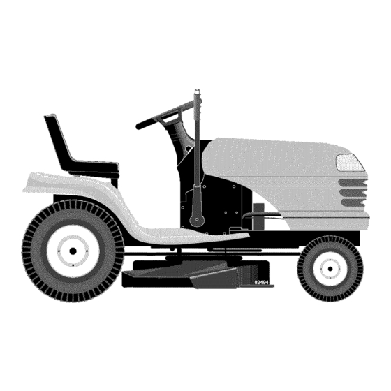
Owner's Manual
CRRFTSMRN °
LAWN TRACTOR
18.5 HP, 42" Mower
Electric Start
6 Speed Transaxle
Model No.
917.275750
[_
his product has a low emission engine which operates
differently
from previously
built engines. Before you start the
engine, read and understand
this Owner's Manual,
IMPORTANT:
Read and follow all Safety
Rules and Instructions
before
operating this equipment.
For answers to your questions about
this product, Call:
1-800-659-5917
Sears Craftsman Help Line
5 am - 5 pm, Mon- Sat
Sears, Roebuck and Co., Hoffman Estates, IL 60179 U.S.A.
Visit our Craftsman
website:www.sears.com/craftsman
Advertisement
Table of Contents

Related Manuals for Craftsman 917.275750


Summary of Contents for Craftsman 917.275750
- Page 1 Read and follow all Safety this product, Call: 1-800-659-5917 Rules and Instructions before Sears Craftsman Help Line operating this equipment. 5 am - 5 pm, Mon- Sat Sears, Roebuck and Co., Hoffman Estates, IL 60179 U.S.A. Visit our Craftsman website:www.sears.com/craftsman...
- Page 2 Service ......Back Cover LIMITED WARRANTY ON CRAFTSMAN RIDING EQUIPMENT For two (2) years from the date of purchase, if this Craftsman Riding Equipment maintained, lubricated and tuned up according to the instructions in the owner's manual, Sears will repair or replace...
- Page 3 IMPORTANT: This cutting machine is capable of amputating hands and feet and throw- ing objects. Failure to observe the following safety instructions could result in serious injury or death. • Never direct discharged material _kWARNING: In order to prevent toward anyone.
- Page 4 II. SLOPE OPERATION • Never carry children, even with the Slopes are a majorfactor relatedto loss of blades shut off. They may fall off and controlandtip-over accidents,which can be seriously injured or interfere with result in severe injury or death. Opera- safe machine operation.
- Page 5 • Keep machine free of grass, leaves, • Removegas-poweredequipmentfrom the truckor trailerand refuelit on the other debris build-up. Clean oil or fuel spillage and remove any fuel-soaked ground.If this is not possible,then debris. Allow machine to cool before refuelsuch equipmentwith a portable storing.
- Page 6 REPAIR PROTECTION Forward: Ground Speed AGREEMENTS (MPH): Congratulations on making a smart pur- chase. Your new Craftsman® product is designed and manufactured for years of dependable operation. But like all products, it may require repair from time to time. That's...
- Page 7 Steering Wheel Steering Wheel Insert (1) Large Flat Washer Boot Steering Steering Wheel Adapter Extension Shaft Steering (1) 5/16 Lock Washer (1) Hex Bolt 5/16-18 Seat (1) Washer 17/32 x 1-3/16 x 12 Gauge _(t) Knob (1) Oil Drain Tube For Future Use Slope Sheet...
- Page 8 Your new tractor has been assembled at the factory with the exception of those parts left unassembled for shipping purposes. To ensure safe and proper operation of your tractor all parts and hardware you assemble must be tightened securely. Use the correct tools as necessary to insure...
- Page 9 7. Slide seat until a comfortableposition NOTE: You may now roll or drive your is reachedwhich allowsyou to press tractor off the skid. Follow the appropriate instruction below to remove the tractor clutch/brakepedal all the way down. from the skid. 8.
- Page 10 CHECK TIRE PRESSURE J CHECKL IS T The tires on your tractor were overin- Before you operate and enjoy your new flated at the factory for shipping purposes. tractor, we wish to assure that you receive Correct tire pressure is important for best the best performance and satisfaction cutting performance.
- Page 11 These symbols may appear on your tractor or in literature supplied with the product. Learn and understand their meaning. I'.,I '_ REVERSE NEUTRAL HIGH CHOKE FAST SLOW IGNITION SWITCH ENGINE OFF REVERSE ENGINE ON ENGINE START PARKING BRAKE PARKING BRAKE PARKING BRAKE OPERATION...
- Page 12 KNOW YOUR TRACTOR READ THIS OWNER'S MANUAL AND SAFETY RULES BEFORE OPERATING YOUR TRACTOR Compare the illustrations with your tractor to familiarize yourself with the locations of various controls and adjustments. Save this manual for future reference. ROS "ON" Position Ignition Switch Attachment Clutch Lever...
- Page 13 The operation of any tractor result in foreign objects thrown into the eyes, which can result in severe eye damage. Always wear safety glasses or eye shields while operating your tractor or performing adjustments or repairs. We recommend a wide vision safety mask over spectacles or standard...
- Page 14 • For best cuttingperformance,grass over 6 inches in height should be mowed Lever High Position twice. Makethe first cut relativelyhigh; Attachment _ the second to desired height. Clutch Lever ,!,_ TO ADJUST GAUGEWHEELS "Engaged' ,"? Position Gaugewheels are properlyadjusted when they are slightly off the groundwhen "Disengag moweris at the desiredcutting height in Position...
- Page 15 TO OPERATE ON HILLS • For cold weather operation you should change oil for easier starting (See the _,WARNING: Do not drive up or down oil viscosity chart in the Maintenance hills with slopes greater than 15 ° and do section of this manual).
- Page 16 NOTE: Before starting, read the warm NOTE: If at a high altitude (above 3000 and cold starting procedures below. feet) or in cold temperatures (below 32 F) Insert key into ignition and turn key the carburetor fuel mixture may need to clockwise to start position and release...
- Page 17 MA,.TE.A.OE SCHEDULE o ¢y F,LL,N OATES AS YOU COMPLETE v,cE O ATHS REGULAR SERVICE Check Brake Operation Check Tire Pressure Check Operator Presence ROS Systems Check for Loose Fasteners Sharpen/Replace Mower Blades Check Battery Level Lubrication Chart Clean Battery and Terminals Check Transaxle Cooling...
- Page 18 TRACTOR • When the engine is running with the ig- nition switch in the ROS "ON" position Always observe safety rules when per- the attachment clutch engaged, any at- forming any maintenance. BRAKE OPERATION tempt by the operator to shift into reverse should NOT shut off the engine.
- Page 19 ENGINE NOTE: Do not use a nail for balancing blade. The lobes of the center hole may LUBRICATION appear to be centered, but are not. Only use high quality detergent oil rated • Slide blade on to an unthreaded portion with API service classification SG-SL.
- Page 20 5. After oil has drained completely, close and lock the drain valve by pushing inward and turning clockwise until the pin is in the locked position as shown. Remove the drain tube and replace cap onto the end of the drain valve. Handle Refill engine with oil through...
- Page 21 MUFFLER CLEANING Inspect and replace corroded muffler • Clean engine, battery, seat, finish, etc. spark arrester (if equipped) as it could cre- of all foreign matter. ate a fire hazard and/or damage. • Keep finished surfaces and wheels free SPARK PLUG(S) of all gasoline, oil, etc.
- Page 22 SERVICE OR ADJUSTMENTS: WARNING: TO AVOID SERIOUS INJURY, BEFORE PERFORMING Depress clutch/brake pedal fully and set parking brake. Place gearshift lever in neutral (N) position. Place attachment clutch in "DISENGAGED" position. Turn ignition key to "STOP" and remove key. Make sure the blades and all moving parts have completely stopped.
- Page 23 TO LEVEL MOWER HOUSING • When distance "D" is 1/8" to 1/2" lower at front than rear, tighten nuts "F" Adjust the mower while tractor is parked on level ground or driveway. Make sure against trunnion on both front links. tires are properly inflated (See "PROD-...
- Page 24 Mandrel With Parking Brake "Engaged" Idler Pulleys Nut "A" Jam Nut Mandrel Pulley TO CHECK AND ADJUST BRAKE Your tractor is equipped with an adjustable 00238 brake system which is mounted on the TO REPLACE MOTION DRIVE BELT right side of the transaxle. Park the tractor on level surface.
- Page 25 TO REMOVE WHEEL FOR REPAIRS Engine Block up axle securely. Remove axle cover, retaining ring and Center washers to allow wheel removal (rear .-Span Clutching wheels have a square key - Do not Keeper lose). Repair tire and reassemble. NOTE: On rear wheels only: align...
- Page 26 TO REPLACE HEADLIGHT BULB TO REMOVE CABLES, REVERSE ORDER Raise hood. Pull bulb holder out of the hole in the BLACK cable first from chassis then from the fully charged battery. backside of the grill. RED cable last from both batteries. Replace bulb in holder and push bulb...
- Page 27 ENGINE IMPORTANT: Damage to the needle valve and the seat in carburetor may result Maintenance, repair, or replacement of the if screw is turned in too tight. emission control devices and systems, which are being done at the customers expense, PRELIMINARY SETTING may be performed...
- Page 28 Immediately prepare your tractor for stor- blended fuels (called gasohol or using age at the end of the season or if the trac- ethanol or methanol) can attract moisture tor will not be used for 30 days or more. which leads to separation and formation acids during...
- Page 29 TROUBLESHOOTING CHART: See appropriate section in manual unless directed to Sears service center PROBLEM CAUSE 3ORRECTION Will not start 1. Out of fuel. Fill fuel tank. See "TO START ENGINE" Engine not "CHOKED" properly. in Operation section. Wait several minutes Engine flooded.
- Page 30 TROUBLESHOOTING CHART: See appropriate section in manual unless directed to Sears service center PROBLEM CAUSE CORRECTION Loss of power Cutting too much grass/too Raise cutting height/reduce fast. speed. Throttle in "CHOKE" position. Adjust throttle control. Clean underside of mower Build-up of grass, leaves and trash under...
- Page 31 TROUBLESHOOTING CHART: See appropriate section in manual unless directed to Sears service center PROBLEM CAUSE CORRECTION Mower blades will 1. Remove obstruction. 1. Obstruction in clutch not rotate mechanism. Worn/damaged mower drive Replace mower drive belt. belt. Frozen idler pulley. Replace idler pulley.
- Page 33 TRACTOR - - MODEL NUMBER 917.275750 SCHEMATIC 02831_193372 BATTERY STARTER ............................SOLENOID FUSE AMMETER (OPTIONAL) BLACK GRAY IGNITION S_'_(_ ,ARK GAP PLUGS UNIT (2 PLUGS • ON TWIN CYL. ENGINES) HOUR BLACK METER (OPTIONAL) HEADLIGHTS NOTE YOUR TRACTOR EQUIPPED WITH A SPECIAL ALTERNATOR SYSTEM.
- Page 34 TRACTOR - - MODEL NUMBER 917.275750 ELECTRICAL...
- Page 35 TRACTOR - - MODEL NUMBER 917.275750 ELECTRICAL PART DESCRIPTION 163465 Battery 74760412 Bolt Hex Hd 1/4-20 unc x 3/4 176689 Box Battery 176138 Switch, Interlock 183759 Harness Asm Light W/4152j 4152J Bulb Light #1156 4799J Cable Battery 6 Ga. 11" red 146147 Cable Battery...
- Page 36 TRACTOR - - MODEL NUMBER 917,275750 CHASSIS AND ENCLOSURES chassis-Laser -It.stk...
- Page 37 TRACTOR - - MODEL NUMBER 917.275750 CHASSIS AND ENCLOSURES PART DESCRIPTION 174619 Chassis 176554 Drawbar 155272 Bumper Hood/Dash 193510X012 Dash STD533710 Bolt, Carriage 3/8-16 x 3/4 174996 Panel, Dash, L.H. 172105X010 Panel, Dash, R.H. 17490608 Screw Thdrol 3/8-16 x 1/2 185682X613 Hood Assembly 184921...
- Page 38 TRACTOR - - MODEL NUMBER 917.275750 GROUND DRIVE 26 27 drive-fender.stlt_38...
- Page 39 TRACTOR - - MODEL NUMBER 917.275750 GROUND DRIVE PART PART DESCRIPTION DESCRIPTION Transaxle Peerless 206-545C 8883R Cover, Pedal (See Breakdown) 175410 Pulley, Engine Bolt, 7/16-20 x 1.5 146682 Spring, Return, Brake 173937 Washer 123666X Pulley, Transaxle 10040700 12000028 Ring, Retainer 154778 Keeper, Belt, Engine,...
- Page 40 TRACTOR - - MODEL NUMBER 917,275750 STEERING ASSEMBLY _2J_39 i!2--37 _7" --'-'-"-36 steedng_pl It 57...
- Page 41 TRACTOR - - MODEL NUMBER 917.275750 STEERING ASSEMBLY PART DESCRIPTION 186780 Steering Wheel 184706 Axle Assembly 169840 Spindle Assembly, 169839 Spindle Assembly, R.H. 6266H Bearing, Race, Thrust, Hardened 121748X Washer 25/32 x 1-5/8 x 16 Ga. 12000029 Ring, Klip 175121 Draglink STD551137 Washer,...
- Page 42 TRACTOR - - MODEL NUMBER 917,275750 ENGINE OPTIONAL EQUIPMENT Spark Arrester engine-bs.lcy! KEY PART PART DESCRIPTION DESCRIPTION 137040 170545X505 Control, Throttle/Choke Line, Fuel 181654 17720408 Screw, Hex Head, Thread Plug Drain Oil Easy 17670412 Cutting 114-20 x 112 Screw, Hex Washer Head, Engine, B&S Model...
- Page 43 TRACTOR - - MODEL NUMBER 917.275750 LIFT ASSEMBLY 13 -..-.._31 lift-rh.lpiece PART PART DESCRIPTION DESCRIPTION 159460 Washer Asm Inner Spring STD624008 Retainer Spring Link Front W/Plunger 173288 159471 Shaft Asm. Lift 73350800 Nut Jam Hex 1/2-13 unc 105767X Pin Groove 175689 Trunnion BIk Zinc...
- Page 44 TRACTOR - - MODEL NUMBER 917.275750 SEAT ASSEMBLY seat It.knob 9 KEY PART KEY PART DESCRIPTION DESCRIPTION 180597 Seat 174648 Bracket Pnt Mounting Switch 180166 121248X Bracket Pnt Pivot Seat (blk) Bushing Snap BIk Nyl 50 Id 71110616 Bolt Fin Hex 3/8-16 unc x 1 72050412 Bolt Rdhd Sht Nk 1/4-20 x 1-1/2...
- Page 45 TRACTOR - - MODEL NUMBER 917,275750 DECALS PART PART DESCRIPTION DESCRIPTION 193308 Decal Oper. instr. 146046 Decal, V-Belt Drive Schematic 193595 Decal Replacement 191551 Decal, Chassis 186280 Decal Hood, R.H. 160396 Decal, V-Belt Schematic 186281 Decal Hood, L.H. 179128 Decal, Deck B 42"...
- Page 46 TRACTOR - - MODEL NUMBER 917,275750 MOWER DECK il 47 118 J" G 42_D_ma n-t-path_stlt...
- Page 47 TRACTOR - - MODEL NUMBER 917.275750 MOWER DECK PART PART DESCRIPTION DESCRIPTION 165892 Mower Deck Assembly, 42" 184907 Arm Assembly, Pad, Brake STD533107 Bolt 178515 Washer, Hardened 138017 Bracket Assembly, Sway Bar, Front 155046 Arm, Idler 165460 Spacer, Retainer Bracket Sway Bar 38142"...
- Page 48 TRACTOR - - MODEL NUMBER 917,274750 PEERLESS TRANSAXLE - - MODEL NUMBER 206-545C MODEL and SERIAL NUMBERS HERE Model et S_riel Ch ffre...
- Page 49 TRACTOR - - MODEL NUMBER 917.274750 PEERLESS TRANSAXLE - - MODEL NUMBER 206-545C REF PART REF PART DESCRIPTION DESCRIPTION Brake Lever Transaxle Cover 790079 772147 Screw 1/4 - 20 x 1-1 /4" 780086A Needle Bearing 5/8" 792073A Screw 1/4 - 20 x 2 1/4" 770128 Transaxle Case 792085A...
- Page 50 TRACTOR - - MODEL NUMBER 917.274750 BRIGGS ENGINE-MODEL NUMBER 31P777, TYPE NUMBER 0299-E1 88, t 11_ 584_ 1330 REPAIR MANUAL 3o7_ 1264_ 11329 REPLACEMENT ENGINE 358 ENGINE GASKET SET 868 _) 943 O 7581 1270 617 0 1022 759 _ 1288 524 _ 8420...
- Page 51 TRACTOR - - MODEL NUMBER 917.274750 BRIGGS ENGINE-MODEL NUMBER 31P777, TYPE NUMBER 0299-E1 1095 VALVE GASKET 1022 8G8 @ 1022 6170 103z [ 524F9 616_::_ 1022 404 # 614 _ 11!9_ 544_ 803 _ 310_ 802 @ 1070 697 " "...
- Page 52 TRACTOR - - MODEL NUMBER 917.274750 BRIGGS ENGINE-MODEL NUMBER 31P777, TYPE NUMBER 0299-E1 105A 127A 142_ _1o6 127 G _L_1°41 276A@ 947A [_ NIKKI ] 1127 276 @ 4311 977 CARBURETOR GASKET 527(_ 276@ 1266 0 121A CARBURETOR OVERHAUL 121 CARBURETOR OVERHAUL 6170 231"_...
- Page 53 TRACTOR - - MODEL NUMBER 917.274750 BRIGGS ENGINE-MODEL NUMBER 31P777, TYPE NUMBER 0299-E1 PART PART DESCRIPTION DESCRIPTION 697174 Cylinder Assembly 690577 Seat-inlet 399265 Kit-Bushing/Seal (Magneto 690464 Valve-Choke (Manual Choke) Side) 108A 695419 Valve-Choke (Nikki) 391086 • Seal-Oil (Magneto Side) 694352 Jet-Main (Standard) 697188...
- Page 54 TRACTOR - - MODEL NUMBER 917.274750 BRIGGS ENGINE-MODEL NUMBER 31P777, TYPE NUMBER 0299-E1 PART PART DESCRIPTION DESCRIPTION 690323 Bolt (Starter Motor) 692424 Terminal-Spark Plug 497608 Brush 690968 Seal-Valve 495859 Armature-Magneto 691108 Screw (Rocker Cover) 691061 Screw (Magneto Armature) 690589 • SeaI-O Ring (Oil Pump Cover) 691043...
- Page 55 SUGGESTED GUIDE FOR SIGHTING SLOPES FOR SAFE OPERATION ONLY RIDE UP AND DOWN HILL, NOT ACROSS HILL 15 DEGREES MAX, down the face of slopes, never across the face. Do not mow ARNING: To avoid serious injury, operate your tractor up and slopes greater than 15 degrees.
- Page 56 Your Home For repair - in your home - of aH major brand appliances, iiiiiiiiiiiiiiiiiiii iiiiiiiiiiiiiiiiiii lawn and garden equipment, or heating and cooling systems, iiiiiiiiiiiiiiiiiii no matter made it, no matter who soJd it! iiiiiiiiiiiiiiiiiii For the replacement parts, accessories owner's manuals that you need to do-it-yourself.