Table of Contents
Advertisement
Available languages
Available languages
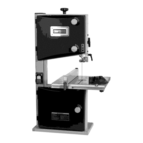
Operator's Manual
CRRFTSMRN °
10"
BAND SAW
Model No.
351.214000
CAUTION:
Read and follow
all Safety Rules and Operating
Instructions
before First Use
of this Product.
Customer
Helpline
1-800-266-9079
Please
have your Model No.
and Serial No. available.
Sears, Roebuck and Co., Hoffman
Estates, IL 60179 U.S.A.
www.sears.com/craftsman
29436.00 Draft (12/08)
Advertisement
Table of Contents

Related Manuals for Craftsman 351.214000


Summary of Contents for Craftsman 351.214000
- Page 1 Helpline CAUTION: Read and follow 1-800-266-9079 all Safety Rules and Operating Please have your Model No. Instructions before First Use and Serial No. available. of this Product. Sears, Roebuck and Co., Hoffman Estates, IL 60179 U.S.A. www.sears.com/craftsman 29436.00 Draft (12/08)
- Page 2 TOOL Do not use power tools in damp or wet locations. Do not expose power tools to rain. If this Craftsman tool fails due to a defect in material or • Work area should be properly lighted. workmanship within one year from the date of purchase, CALL 1-800-4-MY-HOME®...
- Page 3 • Do not force tool. It will work most efficiently at the rate for which it was designed. • Keep hands away from moving parts and cutting surfaces. • Never leave tool running unattended. Turn the power off and do not leave tool until it comes to a complete stop.
- Page 4 Locate four hex bolts and four lock washers from the bag of loose parts. Mount the table to the upper table trunnion and install a bolt with washer in each hole, and then tighten with adjustable wrench. CENTERING THE TABLE •...
- Page 5 STABILIZE MACHINE • To ensure sufficient upright stability of the machine it should be bolted to floor, bench or worktable. For MOTOR this purpose 6mm holes are provided in the The band saw is supplied with a 1_ HP motor. machine's base.
- Page 6 (or green and yellow) wire to a live terminal. The Craftsman 10" Bench Top Band Saw features weld- ed steel frame construction and a solid cast iron table Where a 2-prong wall receptacle is encountered, must be replaced with a properly grounded 3-prong surface to insure durability.
- Page 7 . Keep hands away fromtheblade andallmoving p arts. ADJUSTMENTS . Always weareyeprotection o r faceshield. The blade tracking, tension and blade guides have been . Always stopthebandsawbefore removing scrap properly adjusted at the factory. However, the adjustments pieces fromtable. may change while the saw is in transit. o Never a ttempt t o sawstock thatdoesnothavea flat It is recommended to verify these adjustments before surface, unless a suitable support i s used.
- Page 8 TRACKING THE SAW BLADE Adjust the rear roller guide to be just clear of the back of the saw blade by unlocking the guide adjust- Set the tracking of the saw blade before setting the ing screw (B). blade guides. When the correct adjustment is reached, lock the Once the saw blade is installed and tensioned, track the rear roller guide in position with the guide adjusting...
- Page 9 BLADE THICKNESS • Blade thickness describes the distance between sides of blade. A thicker blade has more rigidity and stronger teeth. • A narrow thick blade is used to cut curves while a wide thin blade is used to make long, straight cuts. BLADE PITCH •...
- Page 10 MITER GAUGE WARNING: Any attempt to repair the motor may cre- ate a hazard unless repair is done by qualified service • Use miter gauge for securing and holding workpiece technician. at desired angle to produce angled cuts. Use scale to adjust gauge to desired angle.
- Page 11 SYM PTO M CORRECTIVE ACTION POSSIBLE CAUSE(S) The machine does not 1. No power supply. 1. Check the cable for breakage. work when switched 2. Defective switch. 2. Replace the lock switch. 3. Defective motor. 3. Replace the motor. The saw blade does 1.
- Page 12 Model 351.21 4000 Figure 23 - Replacement Parts Illustration ..+, ..132 \138 't39 "141...
- Page 13 PART PART PART DESCRIPTION DESCRIPTION DESCRIPTION 29318.00 29343.00 STD833012 Hex. Bolt M6x12* Knurled Knob Cap Blade Tracking Knob Cap 29319.00 Hex. Screw M6x45 29344.00 29366.00 Table Trunion Lower Blade Tracking Knob Body 29320.00 STD833060 Hex. Bolt M6x60* 29367.00 Knurled Knob Body Carriage Bolt M6x16 STD840610...
- Page 14 PART PART PART DESCRIPTION DESCRIPTION DESCRIPTION 29390.00 Knob STD840610 Hex. Nut M6* STD8414420 Hex. Nut M14" 29391.00 29320.00 29424.00 Adjusting Shaft Knurled Knob Body Star Lock Cap 29392.00 Hex. Socket Set Screw M6xl0 29408.00 Hex. Screw M6x45 29425.00 Shaft Mount 29393.00 29318.00 29426.00...
- Page 15 NOTES...
- Page 16 PREPARE EL AREA DE TRABAJO PARA LA TAREA A REALIZAR GARANTIA COMPLETA DE UN ANO PARA • Mantenga el _trea de trabajo limpia. Las _.reas de trabajo HERRAMIENTA CRAFTSMAN desordenadas atraen accidentes. Siesta herramienta Craftsman fallara por causa de defectos •...
- Page 17 • Mantenga todas las partes listas para funcionar. Revise el protector u otras piezas para determinar si funcionan correc- tamente y hacen el trabajo que deben hacer. Verifique que no hayan ocurrido daSos durante el envio. Si hay • Revise que no haya partes daSadas. Verifique el alineamiento daSos, se deber_, presentar...
- Page 18 AJUSTE DE LA MESA PARA PONERLA A ESCUADRA CON LA HOJA DE LA SIERRA Consulte las Figuras 4 y 5. PRECAUClON: Nointente hacer elmontaje sihay partes q ue Afloje la manilla en el mu56n inferior de la mesa y ponga una faltan.
- Page 19 INSTALACION DEL REBORDE PARA ASERRAR A LO LARGO • Coloque el reborde para aserrar a Io largo sobre el riel de guia. Ajuste el reborde para aserrar a Io largo, a fin de que est6 paralelo con la hoja de la sierra. Presione hacia abajo la manivela del reborde para aserrar...
- Page 20 FUENTE DE ALIMENTACION Si se cuenta Qnicamente con un recept_.culo para dos puntas, este deber_t ser reemplazado con un recept_.culo para tres pun- La sierra de banda viene precableada para uso con una fuente tas debidamente conectado a tierra e instalado de acuerdo de alimentaci6n de 120 voltios, 60 Hz.
- Page 21 • Haga cortes de "alivio" antes de cortar curvas largas. La Sierra de Banda de Banco de 10" Craftsman cuenta con un • Destense la hoja cuando no se vaya a utilizar la sierra por un...
- Page 22 AJUSTE DE LA ALTURA DE CORTE • Retire de la mesa el reborde para aserrar a Io largo, el riel guia, la tuerca de mariposa y el tornillo. • La guia superior de la hoja debe colocarse Io m_.s cerca posi- •...
- Page 23 • Afloje el tornillo de ajuste de la guia (C) en cada lado de la AVISO: No ajuste la manivela del reborde de manera que se hoja de la sierra para ajustar las dos guias de rodillo a no ejerza demasiada presidn durante la operacidn;...
- Page 24 TIPO DE CORTE Para un mantenimiento adecuado: • Mantenga la sierra limpia y seca. Limpie donde se hayan • El corte de contorno se hace guiando la pieza de trabajo acumulado virutas o aserrin. mano libre para producir formas curvas. •...
- Page 25 MEDIDA CORRECTIVA SINTOMA CAUSAS(S) POSIBLE(S) La m&quina no funciona 1. No hay suministro el6ctrico. 1. Revise el cable para ver si est& roto. cuando se enciende. 2. Interruptor defectuoso. 2. Reemplace el interruptor bloqueable. 3. Motor defectuoso. 3. Reemplace el motor. La hoja de la sierra no se No se ha apretado la manilla de 1.
- Page 26 NOTAS...
- Page 27 NOTAS...
- Page 28 iiiiiiiiiiiiiiiiiiiiiii;_; _¸¸¸ iiiiiiiiiiiiiiiiiiiiiii ¸ iiiiiiiiiiiiiiiiiii iiiiiiiiiiiiiiiiiii iiiiiiiiiiiiiiiiiii iiiiiiiiiiiiiiiiiii iiiiiiiiiiiiiiiiiii iiiiiiiiiiiiiiiiiii iiiiiiiiiiiiiiiiiii iiiiiiiiiiiiiiiiiii iiiiiiiiiiiiiiiiiii iiiiiiiiiiiiiiiiiii iiiiiiiiiiiiiiiiiii iiiiiiiiiiiiiiiiiii iiiiiiiiiiiiiiiiiii iiiiiiiiiiiiiiiiiii iiiiiiiiiiiiiiiiiii iiiiiiiiiiiiiiiiiii iiiiiiiiiiiiiiiiiii iiiiiiiiiiiiiiiiiii iiiiiiiiiiiiiiiiiii iiiiiiiiiiiiiiiiiii iiiiiiiiiiiiiiiiiii iiiiiiiiiiiiiiiiiii iiiiiiiiiiiiiiiiiii iiiiiiiiiiiiiiiiiii iiiiiiiiiiiiiiiiiii iiiiiiiiiiiiiiiiiii iiiiiiiiiiiiiiiiiii iiiiiiiiiiiiiiiiiii iiiiiiiiiiiiiiiiiii iiiiiiiiiiiiiiiiiii iiiiiiiiiiiiiiiiiii iiiiiiiiiiiiiiiiiii iiiiiiiiiiiiiiiiiii iiiiiiiiiiiiiiiiiii iiiiiiiiiiiiiiiiiii iiiiiiiiiiiiiiiiiii iiiiiiiiiiiiiiiiiii iiiiiiiiiiiiiiiiiii iiiiiiiiiiiiiiiiiii...