Advertisement
Quick Links
Download this manual
See also:
Operator's Manual
Advertisement

Related Manuals for Craftsman 351.218330


Summary of Contents for Craftsman 351.218330
-
Page 1: Assembly Instructions
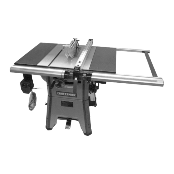
Assembly Instructions 10″ CONTRACTOR TABLE SAW Model No. 351.218330 Sears Brands Management Corporation, Hoffman Estates, IL 60179 U.S.A. www.sears.com/craftsman 31624.00 Draft (10/08/09) -
Page 2: Table Of Contents
Hardware Bag #5 UNPACKING 10/13mm Open End Wrench 4mm Hex Wrench The table saw body comes assembled as one unit. Additional 5mm Hex Wrench parts which need to be fastened to the saw should be located 8mm Hex Wrench and accounted for before assembling: A Extension Table (2) B Dust Chute C Front Rail (2) -
Page 3: Hardware
• Set both panel assemblies upside down on bench and STEP 2 attach the left side panel (stamped ‘B’) to the assemblies made above. • Use the blade tilt handwheel to tilt the blade completely to • Attach the right side panel (stamped ‘C’) to the assembly. 45°. -
Page 4: Hardware
• Refer to Figure 7; loosen and remove the bolt and hex nut STEP 5 from the support. Rotate foot pedal bar so that kick plate cam is inside bracket. The kick plate cam must be under- ATTACH CASTER SETS TO BASE neath the caster to function properly. -
Page 5: M10 X 25 Socket Head
Install the rip fence storage brackets to the right side panel of STEP 7 the base using two screws, flat washers and hex nuts. ATTACH BASE TO CABINET Tools Required: 8mm Hex Wrench Hardware Required: Four M10 x 25 socket head bolts, four M10 lock washers and four M10 flat washers (Hardware bag #4). -
Page 6: Hardware
• Place blade on arbor. Make sure arrow on blade and teeth STEP 10 point towards front of saw. • Replace flange and nut on arbor and securely snug blade ATTACH EXTENSION TABLES in position. Tools Required: 13mm Open End Wrench and Straight Edge Hardware Required: Six M10 x 25 hex head bolts, six M10 lock washers and six M10 flat washers (Hardware bag #1). - Page 7 • After front rails are adjusted level and flat, tighten the Rear screws completely. • Secure all hardware completely. Blade Equal Distances Front Miter Gauge Slots Figure 22 - Use Straight Edge to Align Rail Joint to Blade Figure 20 - Aligning Miter Slots to Blade •...
- Page 8 • Attach brace to the far right end of the rails. Simultaneously slide brace with hex bolts into the rail T- Locking slots and secure in position using lock washers, flat wash- ers and acorn nuts. Screw Locking Knob Bracket Plate Figure 27 - Riving Knife •...
- Page 9 STEP 17 Set Screws ATTACH BLADE GUARD AND ANTI-KICKBACK PAWLS • Place the slot of blade guard body over the riving knife. Slot of bushing is placed in the notch indicated in Figures 29 and 30. • The bushings have a beveled edge and must be located in Latches the center of the slot to lock properly.
- Page 10 STEP 19 STEP 21 INSTALL PUSH STICK SAW COMPLETELY ASSEMBLED • Insert the push stick into brackets on left side of base. Figure 35 Figure 33 STEP 20 INSTALL RIP FENCE • Position rip fence assembly at end of saw. Be certain lock- ing lever is in UP unlocked position.
- Page 11 NOTES...
- Page 12 Get it fixed, at your home or ours! Your Home For expert troubleshooting and home solutions advice: www.managemyhome.com For repair – in your home – of all major brand appliances, lawn and garden equipment, or heating and cooling systems, no matter who made it, no matter who sold it! For the replacement parts, accessories and owner’s manuals that you need to do-it-yourself.