Lenovo ThinkPad T420si User Manual
(english) user guide
Hide thumbs
Also See for ThinkPad T420si:
- Manual do utilizador (256 pages) ,
- Manual d'utilisation (256 pages) ,
- User manual (252 pages)
Table of Contents
Advertisement
Quick Links
Advertisement
Table of Contents
Troubleshooting

Related Manuals for Lenovo ThinkPad T420si


Summary of Contents for Lenovo ThinkPad T420si
-
Page 1: User Guide
User Guide ThinkPad T420s and T420si... - Page 2 • Appendix C “Notices” on page 225 The Safety and Warranty Guide and the Regulatory Notice have been uploaded on the Web site. To refer to them, go to http://www.lenovo.com/support, and then click User guides & manuals. Third Edition (May 2012) ©...
-
Page 3: Table Of Contents
Fingerprint Software... Using the NVIDIA Optimus Graphics feature . . . Lenovo Solution Center ..Using audio features ... . - Page 4 Chapter 4. Security ..71 Performing a warm swap ..Attaching a mechanical lock ..Inserting the hard disk drive into the adapter .
- Page 5 Lenovo Support Web site..Substances Directive (RoHS) ..Calling Lenovo ... . . China RoHS....
- Page 6 User Guide...
-
Page 7: Read This First
© Copyright Lenovo 2012... -
Page 8: Important Safety Information
This information can help you safely use your notebook personal computer. Follow and retain all information included with your computer. The information in this document does not alter the terms of your purchase agreement or the Lenovo Limited Warranty. For more information, see the Safety and Warranty Guide came with your computer. -
Page 9: Conditions That Require Immediate Action
Note: If you notice these conditions with a product (such as an extension cord) that is not manufactured for or by Lenovo, stop using that product until you can contact the product manufacturer for further instructions, or until you get a suitable replacement. -
Page 10: Power Cords And Power Adapters
product are zero. Before you remove the covers from a product equipped with a power cord, always make sure that the power is turned off and that the product is unplugged from any power source. If you have any questions or concerns, contact the Customer Support Center. Although there are no moving parts in your computer after the power cord has been disconnected, the following warnings are required for your safety. -
Page 11: Extension Cords And Related Devices
Hazardous voltage, current, and energy levels are present inside any component that has this label attached. There are no serviceable parts inside these components. If you suspect a problem with one of these parts, contact a service technician. © Copyright Lenovo 2012... -
Page 12: External Devices
In addition, many mobile products, such as notebook computers, utilize a rechargeable battery pack to provide system power when in portable mode. Batteries supplied by Lenovo for use with your product have been tested for compatibility and should only be replaced with approved parts. -
Page 13: Lithium Coin Cell Battery Notice
• Ventilation slots, fans and/or heat sinks are provided with the product for safety, comfort, and reliable operation. These features might inadvertently become blocked by placing the product on a bed, sofa, carpet, or other flexible surface. Never block, cover, or disable these features. © Copyright Lenovo 2012... -
Page 14: Electrical Current Safety Information
• When the ac power adapter is connected to an electrical outlet and your computer, it generates heat. Do not place the adapter in contact with any part of your body while using it. Never use the ac power adapter to warm your body. Extended contact with your body, even through clothing, may cause a skin burn. -
Page 15: Laser Compliance Statement
50332-2 can be dangerous due to excessive sound pressure levels. If your Lenovo computer came with headphones or earphones in the package, as a set, the combination of the headphones or earphones and the computer already complies with the specifications of EN 50332-1. -
Page 16: Additional Safety Information
Additional safety information DANGER Plastic bags can be dangerous. Keep plastic bags away from babies and children to avoid danger of suffocation. Notice for Tablet PC users Safety Notice for users in Australia: DANGER Do not connect phone line while using tablet mode. Notice for users in the U.S.A. -
Page 17: Chapter 1. Product Overview
• “Front view” on page 2 • “Right-side view” on page 5 • “Left-side view” on page 6 • “Rear View” on page 9 • “Bottom view” on page 7 • “Status indicators” on page 10 © Copyright Lenovo 2012... -
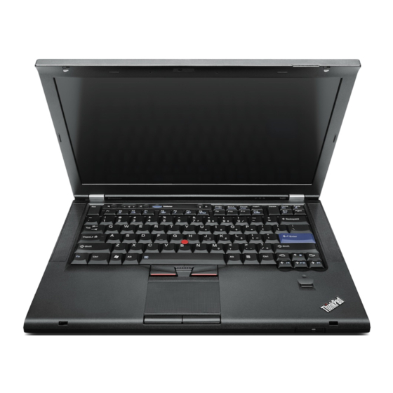
Page 18: Front View
Front view Figure 1. ThinkPad T420s/T420si front view Power switch Computer display ThinkVantage button TrackPoint buttons TrackPoint pointing stick Volume control buttons System and power-status indicators UltraConnect™ wireless antennas (left) Built-in microphone (left) Integrated camera ThinkLight Built-in microphone (right) UltraConnect™ wireless antennas (right) Built-in stereo speaker (right) Forward and Back keys Fingerprint reader... - Page 19 Productivity Center program (for Windows XP and Windows Vista Note: Depending on the date when your computer was manufactured, your computer might have the Lenovo ThinkVantage Toolbox program preinstalled instead of the SimpleTap program or the ThinkVantage Productivity Center program.
- Page 20 For more information about how to use the camera, refer to “Using an integrated camera” on page 60. ThinkLight You can use your computer under less than perfect lighting conditions. ® To illuminate the keyboard, turn on the ThinkLight by pressing Fn+PgUp. To turn it off, press Fn+ PgUp again.
-
Page 21: Right-Side View
Right-side view Figure 2. ThinkPad T420s/T420si right side view Security keyhole Serial Ultrabay Slim Wireless radio switch Security keyhole Your computer comes with a security keyhole. You can purchase a security cable and lock to fit this keyhole. Serial Ultrabay Slim Your computer has a bay for Serial Ultrabay Slim devices. -
Page 22: Left-Side View
Left-side view Figure 3. ThinkPad T420s/T420si left-side view Fan louvers (left) USB connector (left) Combo audio jack Media card reader slot or ExpressCard slot Smart card slot Fan louvers (left) The internal fan and louvers enable air to circulate in the computer and cool the central processor. Note: To avoid impeding airflow, do not place any obstacle in front of the fan. -
Page 23: Bottom View
Media card reader slot or ExpressCard slot Depending on the model, your computer might have a media card reader slot or an ExpressCard slot. • If your computer have a media card reader slot. The media card reader supports the following cards: –... - Page 24 Your computer might include a PCI Express Mini Card in the PCI Express Mini Card slot which enables wireless WAN communications. With Lenovo technologies advancing to provide you with the best engineered systems, some models are equipped with a mSATA solid state drive for data storage.
-
Page 25: Rear View
Rear View Figure 5. ThinkPad T420s/T420si rear view Power jack Ethernet connector USB connector (rear) Always On USB connector DisplayPort connector Monitor connector Fan louvers (rear) Power jack The ac power adapter cable connects to the computer power jack to provide power to the computer and charge the battery. -
Page 26: Status Indicators
USB connector (rear) The Universal Serial Bus connectors are used for connecting devices compatible with a USB interface, such as a printer or a digital camera. Notes: • Your computer is compatible with USB 1.1, 2.0, and 3.0. • If your computer is a USB 3.0 model, any function specific to USB 3.0 will not work until your Windows operating system has been started. - Page 27 System-status indicators Device Access A hard disk drive or an optional drive, such as a drive in the Ultrabay, is being used to read or write data. When this indicator is blinking, do not put the computer into sleep (standby) mode, remove the device from the bay, or turn off the computer.
- Page 28 Sleep (standby in Windows XP) status • Green: The computer is in sleep (standby) mode. • Blinking green: The computer is entering sleep (standby) or hibernation mode, or is resuming normal operation. Battery status • Green: The battery has more than 20% charge. •...
-
Page 29: Locating Important Product Information
Certificate of Authenticity (COA) label. Machine type and model label The machine type and model label identifies your computer. If you contact Lenovo for help, the machine type and model number will enable support technicians to identify your computer and provide the highest level of service. -
Page 30: Fcc Id And Ic Certification Number Label
You can find the machine type and model of your computer in the label as shown below: FCC ID and IC Certification number label There is no FCC ID or IC Certification number for the PCI Express Mini Card shown on the enclosure of your computer. -
Page 31: Certificate Of Authenticity Label
If no integrated wireless PCI Express Mini Card has been preinstalled in your computer, you can install one. To do this, follow the procedure in “Replacing the PCI Express Mini Card for wireless LAN/WiMAX connection” on page 110 or “Replacing the PCI Express Mini Card for Wireless WAN ” on page 119. Certificate of Authenticity label The Certificate of Authenticity label for the preinstalled operating system is attached. - Page 32 • mSATA solid state drive (on some models) Display The color display uses TFT technology: • Size: 14.01 inch (355.6 mm) • Resolution: – LCD: Up to 1600-by-900, depending on the model – External monitor: Up to 2048-by-1536 • Brightness control •...
-
Page 33: Specifications
• Integrated WiMAX (on some models) Security features • Fingerprint reader (on some models) Specifications Size • Width: 343.0 mm (13.5 inch) • Depth: 230.0 mm (9.05 inch) • Height: 21.2 to 26.0mm (0.83 inch to 1.02 inch) Environment: • Maximum altitude without pressurization: 3048 m (10,000 ft) •... -
Page 34: Thinkvantage Technologies And Software
Do not eat or smoke over your keyboard. Particles that fall into your keyboard can cause damage. ThinkVantage Technologies and software Lenovo preinstalls on your PC useful and helpful software applications to help you get started, to stay productive while on the move and to keep you and your computer working. Lenovo offers enhanced security, wireless computing, data-migration and other solutions for your computer. - Page 35 Note: If you do not find the application you need in Control Panel, open the Lenovo ThinkVantage Tools application navigation window and double-click the dimmed icon to install the application you need.
-
Page 36: Access Connections
Table 2. Applications on Control Panel (continued) Application Control Panel section Green text on the Control Panel Recovery Media System and Security Lenovo - Factory Recovery Disks Programs SimpleTap Lenovo - SimpleTap System Update System and Security Lenovo - Update and Drivers... -
Page 37: Fingerprint Software
For detailed information, see “Diagnosing problems” on page 181. To start the Lenovo Solution Center program in Windows 7, see “Accessing applications in Windows 7” on page 18. Lenovo ThinkVantage Tools... -
Page 38: Message Center Plus
To start the Lenovo ThinkVantage Toolbox program, do the following: • For Windows 7: See “Accessing applications in Windows 7” on page 18. • For Windows Vista and Windows XP: Click Start ➙ All Programs ➙ ThinkVantage ➙ Lenovo ThinkVantage Toolbox. -
Page 39: Product Recovery
(ThinkVantage applications, device drivers, UEFI BIOS updates, and other third party applications). Some examples of software that you should keep updated are programs provided by Lenovo, such as the Rescue and Recovery program. To open the System Update, do the following: •... -
Page 40: Thinkvantage Productivity Center
The ThinkVantage Productivity Center program provides an integrated user interface to help you set up, understand, and enhance your computer. It enables you to access other ThinkVantage Technologies, view messages from Lenovo, and perform the most frequently used tasks such as device configuration, wireless network configuration, and computer management and maintenance. -
Page 41: Chapter 2. Using Your Computer
“Using the media card reader” on page 61 Register your computer When you register your computer, information is entered into a database, which enables Lenovo to contact you in case of a recall or other severe problem. In addition, some locations offer extended privileges and services to registered users. - Page 42 Getting connected in different locations is a challenge? • To troubleshoot a wireless networking issue, go to: http://www.lenovo.com/support/faq • Take advantage of the networking features by use of Access Connections. • To learn more about using the wireless features of your computer, refer to “Wireless connections” on page 43.
-
Page 43: Special Keys And Buttons
Vista). Note: Depending on the date when your computer was manufactured, your computer might have the Lenovo ThinkVantage Toolbox program preinstalled instead of the SimpleTap program or the ThinkVantage Productivity Center program. You also can use the ThinkVantage button to interrupt the startup sequence of your computer and start the Rescue and Recovery workspace, which runs independently of the Windows operating system and is hidden from it. -
Page 44: Function Key Combinations
If the numeric keypad is enabled, press and hold Shift to use the cursor- and screen-control keys temporarily. Note: The functions of the cursor- and screen-control keys are not printed on the keys. Function key combinations By setting the function keys, you can change operational features instantly. To use this function, press and hold the Fn key (1);... - Page 45 Power conservation • Fn+F3 Select a power plan (in Windows XP, power scheme) that has been created by Power Manager, or adjust the power level by using the slider control. When you press this combination of buttons, a panel for selecting a power plan (in Windows XP, power scheme) or adjusting the power level appears.
- Page 46 Apply a presentation scheme directly, with no need to start Presentation Director. To disable this function and use the Fn+F7 key combination for switching a display output location, start Presentation Director, and change the settings. Click Start ➙ All Programs ➙ ThinkVantage ➙ Presentation Director. For information on applying a presentation scheme, refer to “Presentation Director”...
- Page 47 For information on the wireless features, refer to “Wireless connections” on page 43. Launching the camera and audio settings • Fn+F6 If you press Fn+F6, the camera and audio settings window is opened and the camera preview is turned on. From this window, you can change the camera and audio settings.
-
Page 48: Volume And Mute Buttons
Volume and mute buttons You can adjust the sound level of the built-in speakers by using the following three buttons: Speaker mute button Volume control button Microphone mute If you mute the sound and then turn off your computer, the sound will remain muted when you turn on your computer again. -
Page 49: Windows Key And Application Key
volume, move the volume control slider up or down. To turn off the sound, select Mute speakers (in Windows Vista and Windows XP, Mute). • The names of windows or fields are slightly different depending on the operating system you use. •... -
Page 50: Using The Ultranav Pointing Device
To display the shortcut menu for an object, select the object on the desktop or within an application and then press this key. Using the UltraNav pointing device Your computer may come with the UltraNav pointing device. The UltraNav consists of the TrackPoint and the touch pad, each of which is itself a pointing device with both basic and extended functions. - Page 51 If you are not familiar with the TrackPoint, these instructions will help you get started: 1. Place your hands in the typing position, and press gently with either index finger on the pointing stick in the direction in which you want the pointer to move. To move the pointer, press the pointing stick away from you to move it up, toward you to move it down, to one side or the other to move it sideways.
-
Page 52: Using The Touch Pad
Note: If you replace the keyboard, a new keyboard is shipped with the default cap. If you wish, you can keep the cap from your old keyboard and use it on the new one. Using the touch pad The touch pad consists of a pad (1) and two click buttons below the TrackPoint buttons at the bottom of the keyboard. -
Page 53: Behavior Of The Ultranav And An External Mouse
2. Click Manage Settings to open the Mouse properties window. 3. Click the UltraNav tab and proceed to customizing the touch pad. For details, refer to the Help in the Utility. Behavior of the UltraNav and an external mouse By default, the TrackPoint and the touch pad are set to Enabled. Note: If you want to attach an external mouse to a USB connector, select “Disabled.”... -
Page 54: Touch Panel
5. Click OK or Apply. 6. If your computer is a Windows 7 model, click Show hidden icons in the task bar. The UltraNav icon is displayed. To add it to the task bar permanently, click Customize and proceed to customize the settings. You can now change the properties of UltraNav by clicking the UltraNav icon on the system tray. -
Page 55: Checking Battery Status
Do more, save more and spend more time unplugged with ThinkPad batteries. Mobility has revolutionized business by allowing you to take your work where ever you go. With ThinkPad batteries, you will be able to work longer without being tied to an electrical outlet. Checking battery status The Power Manager Battery Gauge in the task tray displays the percentage of battery power remaining. -
Page 56: Charging The Battery
Charging the battery When you check battery status and find that the percentage of power remaining is low or when the power alarm alerts you that remaining power is low, you need to charge your battery or replace it with a charged battery. - Page 57 1. Press Fn+F3. A panel for selecting a power plan (in Windows XP, power scheme) appears. 2. Select Fn+F3 Settings. 3. Select Power off display. 4. Click OK. The next time you press Fn+F3, you can turn off the computer display. •...
-
Page 58: Handling The Battery
OK. Handling the battery This system does not support batteries that are not genuine Lenovo-made or authorized. The system will continue to boot, but may not charge unauthorized batteries. Attention: Lenovo has no responsibility for the performance or safety of unauthorized batteries, and provides no warranties for failures or damage arising out of their use. -
Page 59: Connecting To The Network
DANGER Only recharge the battery pack strictly according to instructions included in the product documentation. DANGER Do not put the battery pack in trash that is disposed of in landfills. When disposing of the battery, comply with local ordinances or regulations and your company's safety standards. DANGER There is a danger of an explosion if the backup battery is incorrectly placed. - Page 60 Your computer can be wireless upgradeable. This means that your computer has an antenna that can support wireless LAN access when wireless LAN access points are available. Wireless devices are available from Lenovo. For more information, see “Finding ThinkPad options” on page 129. User Guide...
-
Page 61: Using Bluetooth
Using wireless WAN connections Wireless Wide Area Network (wireless WAN) enables you to establish wireless connections over remote public or private networks. These connections can be maintained over a large geographical area, such as a city or an entire country, by use of multiple antenna sites or satellite systems maintained by wireless service providers. - Page 62 Using Bluetooth for the first time on your computer If this is the first time Bluetooth has been used on your computer, follow either of the following procedures: 1. Double-click the My Bluetooth Places icon on the desktop, or the Bluetooth icon in the task bar. The Start Using Bluetooth window opens, and some virtual device drivers are installed automatically.
- Page 63 • Fax • File transfer • PIM item transfer • Dial-up networking • Network access • Bluetooth serial port • Bluetooth Imaging • Hands Free • AV profile 4. Click the service you want. For more information, press the F1 key to open the online help for Bluetooth. Bluetooth Configuration To use the configuration features of Bluetooth, right-click the icon.
- Page 64 2. Click Start ➙ Run. 3. Type C:\SWTOOLS\Drivers\TPBTooth\Setup.exe (or specify the full path to the setup.exe file you have downloaded from http://www.lenovo.com/support); then click OK. 4. Click Next. 5. Select I accept the terms in the license agreement; then click Next.
- Page 65 Note: If you use the wireless feature (the 802.11 standard) of your computer simultaneously with a Bluetooth option, data transmission speed can be delayed and the performance of the wireless feature can be degraded. Using WiMAX Some ThinkPad notebooks come with a built-in wireless LAN card integrating WiMAX technology. WiMAX, a long-range wireless data transmission technology based on the 802.16 standard, provides you with a “last mile”...
- Page 66 Access Connections icon and wireless status icon The Access Connections icon displays general connection status. The wireless status icon displays the signal strength and status of your wireless connection. You can find more detailed information about the signal strength and status of your wireless connection either by opening Access Connections or by double-clicking the Access Connections wireless status icon in the task bar.
-
Page 67: Using A Projector Or External Display
• Click the Access Connections wireless status icon in the system tray. • Click Power Off Wireless Radio. Notes: • You can use the wireless radio switch to disable the wireless radio of all the wireless devices on your computer. •... -
Page 68: Connecting A Projector Or External Display
2. Click Display at the left. 3. Click Change display settings. 4. Click Advanced settings, select the On Screen Display tab, and then click Num Lock Settings. 5. The setting window opens. 6. Follow the instructions on the screen. For Windows Vista: 1. - Page 69 For Windows Vista: 1. Connect the external monitor to the monitor connector; then connect the monitor to an electrical outlet. 2. Turn on the external monitor. 3. If this is the first time the external monitor has been connected, the New Display Detected dialog box opens.
- Page 70 8. Click Properties. If you are prompted for an administrator password or confirmation, type the password or provide confirmation. 9. Click the Driver tab. 10. Click Update Driver. 11. Click Browse my computer for driver software, and then click Let me pick from a list of device drivers on my computer.
- Page 71 3. Press Fn+F7 to change the display output location to the external monitor. 4. Right-click on the desktop, and click Properties to open the Display Properties window. 5. Click the Settings tab. 6. Click Advanced. 7. Click the Monitor tab. Check the monitor information window to make sure that the monitor type is correct.
-
Page 72: Setting Up A Presentation
1. Switch the Graphics Processing Unit (GPU) to High Performance Graphics. For more information about GPU switching, refer to the help for ThinkPad Power Manager. Note: If your computer is running Windows XP, you cannot switch the GPU. 2. Right-click on the desktop and select NVIDIA Control Panel. The NVIDIA Control Panel opens. 3. -
Page 73: Using Dual Displays
Note: It may take several seconds before the projector displays the image. If you do not see your desktop displayed after 60 seconds, try pressing Fn+F7 to switch between different display output locations. You can create a presentation scheme by following the instructions of the Presentation Director, with the projector attached to your computer. - Page 74 6. Place the icons for the monitors so that they touch. Note: You can set the monitors in any relative position, but the icons must touch each other. 7. Click OK to apply the changes. Note: To change the color settings, right-click on the desktop, and click Screen resolution. Click Advanced Settings, select the Monitor tab, then set Colors For Windows Vista: 1.
-
Page 75: Using The Nvidia Optimus Graphics Feature
Using the NVIDIA Optimus Graphics feature Some ThinkPad notebooks support NVIDIA Optimus Graphics. NVIDIA Optimus Graphics enables a dynamic switch, that is, a switch with no need to restart your computer between High Performance and Energy Saving Graphics. Note: To use the DisplayPort feature or DVI monitor on the docking station, you need to switch to High Performance Graphics. -
Page 76: Using An Integrated Camera
The following table shows which functions of the audio devices attached to the jacks on your computer or docking station are supported. Table 3. Audio feature list Headset with a 3.5 mm Conventional headphone Conventional microphone 4-pole plug Combo audio jack Headphone and Headphone function Not supported... -
Page 77: Using The Thinklight Feature
Configuring camera settings You can configure the camera settings to meet your needs, such as adjusting the quality of the video output. To configure the camera settings, do the following: 1. Press Fn+F6. The Communications settings window opens. 2. Click the Manage Settings button. The Communications Utility window opens. 3. -
Page 78: Inserting An Expresscard, A Flash Media Card, Or A Smart Card
• “Inserting an ExpressCard, a flash media card, or a smart card” on page 62. • “Removing an ExpressCard, a flash media card or a smart card” on page 62. Inserting an ExpressCard, a flash media card, or a smart card Attention: •... - Page 79 • Before removing a storage ExpressCard, such as a flash memory ExpressCard, a solid state ExpressCard, or a memory card reader ExpressCard, from an ExpressCard slot, you must stop the ExpressCard. Otherwise, data on the ExpressCard might be corrupted or lost. •...
- Page 80 User Guide...
-
Page 81: Copyright Lenovo
By keeping these considerations in mind, you can improve performance and achieve greater comfort. Lenovo is committed to providing the latest information and technology to our customers with disabilities. Refer to our accessibility information which outlines our efforts in this area. -
Page 82: Adjusting Your Computer To Fit You
Note that there are many ThinkPad product solutions available to help you modify and expand your computer to best suit your needs. Access the following Web site to view some of these options at http://www.lenovo.com/accessories/services/index.html. Explore your options for docking solutions and external products that can provide the adjustability and features that you want. -
Page 83: Accessibility Information
Accessibility information Lenovo is committed to providing people with disabilities greater access to information and technology. As a result, the following information provides ways to help users that have hearing, vision, and mobility limitations get the most out of their computer experience. -
Page 84: Traveling With Your Computer
To disable the FullScreen Magnifier function, click the FullScreen Magnifier icon and select Exit or press Fn+Spacebar . Traveling with your computer When you travel abroad, your computer can help you feel more at home and at ease. With your own computer and its files, you can be confident about gathering and offering information to clients and coworkers. - Page 85 If you are traveling to another country you might want to consider these items • An ac power adapter for the country that you are traveling to • An adapter to connect to a phone line in that country Other items you may wish to consider •...
- Page 86 User Guide...
-
Page 87: Chapter 4. Security
Refer to the instructions shipped with the mechanical lock. Note: You are responsible for evaluating, selecting, and implementing the locking devices and security features. Lenovo makes no comments, judgments, or warranties about the function, quality, or performance of locking devices and security features. -
Page 88: Passwords And Sleep (Standby) Mode
• “Hard disk security” on page 77 • “Supervisor password” on page 75 Passwords and sleep (standby) mode If you have set passwords and you put your computer into sleep (standby) mode by pressing Fn+F4, the procedure for resuming operation is as follows: •... -
Page 89: Hard Disk Passwords
10. Commit your password to memory. Note: You might want to note your power-on password in a safe place. Otherwise, if you forget it, you have to take your computer to a Lenovo reseller or a marketing representative to have the password canceled. - Page 90 Lenovo cannot reset your passwords or recover data from the hard disk. You must take your computer to a Lenovo reseller or a marketing representative to have the hard disk drive replaced. Proof of purchase is required, and a fee will be charged for parts and service.
-
Page 91: Supervisor Password
• To remove the user hard disk password, type the current master hard disk password in the Enter Current Password field. Then leave the Enter New Password and Confirm New Password fields blank, and press Enter. A Setup Notice window is displayed. Press F10 to exit from the Setup Notice window. Both the user and master hard disk passwords will be removed. - Page 92 Attention: You might want to note your password and keep it in a safe place. If you forget your supervisor password, Lenovo can not reset your password. You must take your computer to a Lenovo reseller or a Lenovo marketing representative to have the system board replaced. Proof of purchase is required, and a fee will be charged for parts and service.
-
Page 93: Hard Disk Security
Hard disk security Your computer supports an enhanced security solution for solid state drive or hard disk drive. To protect passwords from unauthorized security attacks, several of the latest technologies and algorithms are integrated into UEFI BIOS and hardware design of ThinkPad notebooks. To maximize security, do the following: 1. -
Page 94: Setting The Security Chip
of a hardware encryption chip. For the efficient use of the encryption feature, be sure to set a hard disk password for the internal storage device. Setting the security chip Strict security requirements are imposed on network client computers that transfer confidential information electronically. -
Page 95: Using A Fingerprint Reader
Enrolling your fingerprint 1. Turn on your computer. 2. To start Lenovo Fingerprint software, refer to “Fingerprint Software” on page 21. 3. Follow the instructions on the screen to enroll your fingerprint. For details, refer to the Help for the program. - Page 96 Lenovo authorized servicer or a marketing representative to have the password canceled.
- Page 97 If you forget your hard disk password, Lenovo cannot reset your password or recover data from the hard disk. You must take your computer to a Lenovo authorized servicer or a marketing representative to have the hard disk drive replaced. Proof of purchase is required, and a fee will be charged for parts and service.
-
Page 98: Notice On Deleting Data From Your Hard Disk Drive Or Solid State Drive
• Use the Delete command. • Format your hard disk drive or solid state drive, using the software for initializing it. • Using the recovery program, provided by Lenovo, bring the hard disk drive or the solid state drive back to factory-ship state. -
Page 99: Protecting Data Against Viruses
Lenovo provides a full version of antivirus software on your computer with a free 30-day subscription. After 30 days, you must renew the license to continue receiving the antivirus software updates. - Page 100 User Guide...
-
Page 101: Chapter 5. Recovery Overview
Chapter 5. Recovery overview This chapter provides information about the recovery solutions provided by Lenovo. This chapter contains the following topics: • “Creating and using recovery media” on page 85 • “Performing backup and recovery operations” on page 87 •... -
Page 102: Creating Recovery Media
“creating Product Recovery discs”. • To create recovery media on the Windows 7 operating system, click Start ➙ All Programs ➙ Lenovo ThinkVantage Tools ➙ Factory Recovery Disks. Then, follow the instructions on the screen. -
Page 103: Performing Backup And Recovery Operations
• To perform a backup operation using the Rescue and Recovery program on the Windows 7 operating system, do the following: 1. From the Windows desktop, click Start ➙ All Programs ➙ Lenovo ThinkVantage Tools ➙ Enhanced Backup and Restore. The Rescue and Recovery program opens. -
Page 104: Using The Rescue And Recovery Workspace
1. From the Windows desktop, click Start ➙ All Programs ➙ Lenovo ThinkVantage Tools ➙ Enhanced Backup and Restore. The Rescue and Recovery program opens. 2. In the Rescue and Recovery main window, click the Launch advanced Rescue and Recovery arrow. -
Page 105: Creating And Using A Rescue Medium
• To create a rescue medium on the Windows 7 operating system, do the following: 1. From the Windows desktop, click Start ➙ All Programs ➙ Lenovo ThinkVantage Tools ➙ Enhanced Backup and Restore. The Rescue and Recovery program opens. -
Page 106: Reinstalling Preinstalled Applications And Device Drivers
• If you have created a rescue medium using a disc, use the following instructions to use the rescue medium: 1. Turn off your computer. 2. Repeatedly press and release the F12 key when turning on the computer. When the Startup Device Menu opens, release the F12 key. -
Page 107: Solving Recovery Problems
Double-click the file, and follow the instructions on the screen. Attention: If you need updated device drivers, do not download them from the Windows Update Web site. Obtain them from Lenovo. For more information, see “Making sure device drivers are current” on page 176. Solving recovery problems... - Page 108 User Guide...
-
Page 109: Chapter 6. Replacing Devices
• Do not place the part on the computer cover or other metal surface. Replacing memory Before you start, print these instructions. Prerequisites for the procedure When replacing the memory, be sure to follow the precautions © Copyright Lenovo 2012... - Page 110 Note: The operating speed of the memory module depends on the system configuration of your computer and its combination with the memory module installed on your computer. In some conditions, the memory in your computer may not be able to operate at the maximum speed. Attention: Before you start installing a module, touch a metal table or a grounded metal object.
- Page 111 6. With the notched end of the SO-DIMM toward the contact edge side of the socket, insert the SO-DIMM into the socket at an angle of about 20 degrees (1); then press it in firmly (2). Note: If you install a memory module in only one of the two memory slots, install it in the lower slot. 7.
-
Page 112: Replacing The Backup Battery
If the backup battery is incorrectly replaced, there is danger of an explosion. The backup battery contains a small amount of harmful substances. To avoid possible injury: • Replace only with a battery of the type recommended by Lenovo. • Keep the battery pack away from fire. -
Page 113: Replacing The Battery
Replacing the battery Before you start, print these instructions. This system does not support batteries that are not genuine Lenovo-made or authorized. The system will continue to boot, but may not charge unauthorized batteries. Attention: Lenovo has no responsibility for the performance or safety of unauthorized batteries, and provides no warranties for failures or damage arising out of their use. - Page 114 If the rechargeable battery pack is incorrectly replaced, there is danger of an explosion. The battery pack contains a small amount of harmful substances. To avoid possible injury: • Replace only with a battery of the type recommended by Lenovo. • Keep the battery pack away from fire.
-
Page 115: Replacing The Hard Disk Drive
Before you start, print these instructions. You can replace the hard disk drive with a new one which can be purchased from your Lenovo reseller or a marketing representative. To replace the hard disk drive, read the following prerequisites, and select your model from the list below for instruction. - Page 116 • Do not drop the drive or subject it to physical shocks. Put the drive on a material, such as soft cloth, that absorbs any physical shocks. • Do not apply pressure to the cover of the drive. • Do not touch the connector. The drive is very sensitive.
- Page 117 6. Detach the side rubber rails from the hard disk drive. 7. Attach the side rubber rails to a new hard disk drive. 8. Insert the hard disk drive into the hard disk drive bay, then press it firmly into place. Chapter 6 Replacing devices...
-
Page 118: Replacing The Keyboard
9. Reinstall the cover of the bay (1), then reinstall the screw (2). 10. Reinstall the battery. For more information about how to reinstall the battery. refer to “Replacing the battery” on page 97. 11. Turn the computer over again. Connect the ac power adapter and the cables to the computer. Replacing the keyboard Before you start, print these instructions. - Page 119 4. Loosen the screws on the memory slot cover (1), then remove the cover (2). 5. Remove the two screws. 6. Turn the computer over and open the display. Chapter 6 Replacing devices...
- Page 120 7. Push hard in the direction shown by the arrows (1) in the drawing to unlatch the front side of the keyboard. The keyboard will open up slightly (2). 8. Carefully lift the keyboard until you can see how it's connected. Hold the keyboard above the computer, and then detach the connector (1).
- Page 121 Installing the keyboard 1. Attach the connector. 2. Insert the keyboard. Make sure that the front edges of the keyboard are under the frame, as shown by the arrows, and press down the keyboard. Chapter 6 Replacing devices...
- Page 122 3. Slide the keyboard as shown by the arrows. 4. Close the computer display, and turn the computer over. Reinstall two screws. 5. Put the memory slot cover back in place (1), close the cover (2), and then tighten the screws (3). User Guide...
-
Page 123: Replacing The Msata Solid State Drive
Some ThinkPad models have an mSATA solid state drive. You can replace the mSATA solid state drive with a new one, which can be purchased from your Lenovo reseller or a marketing representative. To replace the mSATA solid state drive, read the following prerequisites. - Page 124 5. Remove the screw (1). The card pops up (2). 6. Remove the card. User Guide...
- Page 125 7. Align the contact edge of a new mSATA solid state drive with the corresponding socket. Notes: • You can also replace the mSATA solid state drive with a Wireless PCI Express Mini Card for Wireless WAN. • To install a new PCI Express Mini Card, refer to “Replacing the PCI Express Mini Card for Wireless WAN ”...
-
Page 126: Replacing The Pci Express Mini Card For Wireless Lan/Wimax Connection
10. Reinstall the battery. For more information about how to reinstall the battery, refer to the instructions in “Replacing the battery” on page 97. 11. Turn the computer over again. Connect the ac power adapter and cables to the computer; then turn it on. Replacing the PCI Express Mini Card for wireless LAN/WiMAX connection Before you start, print these instructions. - Page 127 4. Loosen the screws on the memory slot cover (1), then remove the cover (2). 5. If a tool for removing connectors is included in the package with the new card, use it to disconnect the cables from the card. If no such tool is included, disconnect the cables by picking up the connectors with your fingers and gently unplugging them.
- Page 128 6. Remove the screw (1). The card pops up (2). 7. Remove the card. User Guide...
- Page 129 8. Align the contact edge of the new PCI Express Mini Card with the corresponding socket contact of the computer. Note: If the new PCI Express Mini Card has two connectors, as in the next drawing, put the white cable in the cable protection tube.
- Page 130 9. Pivot the card until you can snap it into place by pressing the upper side of the connectors (1), and secure the card with the screw (2). 10. Connect the cables to the new PCI Express Mini Card. Be sure to attach the gray cable to the connector marked “MAIN”...
- Page 131 11. Put the memory slot cover back in place (1), close the cover (2), and then tighten the screws (3). 12. Reinstall the battery. For more information about how to reinstall the battery, refer to “Replacing the battery” on page 97. 13.
- Page 132 5. If a tool for removing connectors is included in the package with the new card, use it to disconnect the cables from the card. If no such tool is included, disconnect the cables by picking up the connectors with your fingers and gently unplugging them. 6.
- Page 133 7. Remove the card. 8. Align the contact edge of the new card with the corresponding socket contact of the computer. Note: If the new PCI Express Mini Card has two connectors, as in the next drawing, put the white cable in the cable protection tube.
- Page 134 9. Pivot the card until you can snap it into place by pressing the upper side of the connectors (1), and secure the card with the screw (2). 10. Connect the cables to the new PCI Express Mini Card. Be sure to attach the gray cable to the connector marked “TR1”...
-
Page 135: Replacing The Pci Express Mini Card For Wireless Wan
11. Put the memory slot cover back in place (1), close the cover (2), and then tighten the screws (3). 12. For more information about how to reinstall the battery, refer to “Replacing the battery” on page 97. 13. Turn the computer over again. Connect the ac power adapter and cables to the computer; then turn it on. Replacing the PCI Express Mini Card for Wireless WAN Before you start, print these instructions. - Page 136 4. Loosen the screws on the memory slot cover (1), then remove the cover (2). 5. If a tool for removing connectors is included in the package with the new card, use it to disconnect the cables from the card. If no such tool is included, disconnect the cables by picking up the connectors with your fingers and gently unplugging them.
- Page 137 6. Remove the screw (1). The card pops up (2). 7. Remove the card. 8. Align the contact edge of the new PCI Express Mini Card with the corresponding socket. Chapter 6 Replacing devices...
- Page 138 9. Pivot the card until you can snap it into place by pressing the upper side of each connector (1). Secure the card with the screw (2). 10. Connect the cables to the new PCI Express Mini Card. Note: Depending on the system configuration of your computer, the card may have only one connector. User Guide...
-
Page 139: Replacing The Sim Card
11. Put the memory slot cover back in place (1), close the cover (2), and then tighten the screws (3). 12. Reinstall the battery. For more information about how to reinstall the battery, refer to “Replacing the battery” on page 97. 13. -
Page 140: Replacing The Solid State Drive
Before you start, print these instructions. You can replace the solid state drive with a new one which can be purchased from your Lenovo reseller or a marketing representative. To replace the solid state drive, read the following prerequisites and select your model from the list below for instructions. - Page 141 • Do not drop the drive or subject it to physical shocks. Put the drive on a material, such as soft cloth, that absorbs any physical shocks. • Do not apply pressure to the cover of the drive. • Do not touch the connector. The drive is very sensitive.
- Page 142 6. Detach the side spacer rails from the solid state drive. 7. Attach the side spacer rails to a new solid state drive. 8. Insert the solid state drive into the solid state drive bay, then press it firmly into place. User Guide...
- Page 143 9. Reinstall the cover of the bay (1), then reinstall the screw (2). 10. Reinstall the battery. For more information about how to reinstall the battery, refer to “Replacing the battery” on page 97. 11. Turn the computer over again. Connect the ac power adapter and the cables to the computer. Chapter 6 Replacing devices...
- Page 144 User Guide...
-
Page 145: Chapter 7. Enhancing Your Computer
You can shop at Lenovo 24 hours a day, 7 days a week directly over the World Wide Web. All you need is an Internet connection and a credit card. -
Page 146: Performing A Hot Swap
2. Unlock the bay lock latch (1) by sliding it to the top. While holding the bay lock latch in the unlocked position, slide the bay eject latch (2) to the left, then pull out the Ultrabay device (3). 3. Insert the replaceable device into the bay; then press the device firmly into the connector. Performing a hot swap To do a hot swap is to connect, remove, or reconnect a device while the computer is operating. -
Page 147: Performing A Warm Swap
2. Unlock the bay lock latch (1) by sliding it to the top. While holding the bay lock latch in the unlocked position, slide the bay eject latch (2) to the left, then pull out the Ultrabay device (3). 3. Insert the replaceable device into the bay; then press the device firmly into the connector. Note: If a hard disk password is set on a hard disk drive, you cannot hot-swap the drive. - Page 148 1. Unlock the bay lock latch (1) by sliding it to the top. While holding the bay lock latch in the unlocked position, slide the bay eject latch (2) to the left, then pull out the Ultrabay device (3). Note: The computer returns from sleep (standby) mode and the pop-up window appears; then the computer automatically goes into sleep (standby) mode again.
-
Page 149: Inserting The Hard Disk Drive Into The Adapter
2. Insert the replaceable device into the bay; then press the device firmly into the connector. 3. Press the Fn key to return from sleep (standby) mode. Inserting the hard disk drive into the adapter The ThinkPad Serial Hard Drive Bay Adapter III (hard disk drive adapter), which is available as an option, enables you to upgrade the capacity of your computer by installing a secondary hard disk drive. - Page 150 3. Insert the hard disk drive with the label facing upward as shown: Note: If your hard disk drive has a strap, be sure not to leave it under the drive. 4. Connect the hard disk drive to its connector. User Guide...
-
Page 151: Inserting The Hard Disk Drive Adapter Into The Bay
5. Close the hard disk drive stopper. Notes: • Make sure that the hard disk drive is inserted tightly into the hard disk drive adapter. • Do not push the cover too hard; you could damage the hard disk drive or the hard disk drive adapter. •... -
Page 152: Thinkpad Port Replicator Series 3, Thinkpad Mini Dock Series 3, Thinkpad Mini Dock Plus Series 3, And Thinkpad Mini Dock Plus Series 3 (170 W)
When you insert the hard disk drive adapter into the bay, make sure that you insert it firmly. If you want to secure your hard disk drive adapter, install a hex-head screw (included in the shipping contents) into the screw hole. ThinkPad Port Replicator Series 3, ThinkPad Mini Dock Series 3, ThinkPad Mini Dock Plus Series 3, and ThinkPad Mini Dock Plus Series 3 (170 W) - Page 153 The sliding adjuster is a guide up the docking connector on your computer as you attach the ThinkPad Port Replicator Series 3. The docking connector is where you attach your computer. ThinkPad Mini Dock Series 3 The power switch turns the computer on and off. The key lock indicator lights when the system lock key is in the locked position.
-
Page 154: Thinkpad Mini Dock Plus Series 3, And Thinkpad Mini Dock Plus Series
ThinkPad Mini Dock Plus Series 3 and ThinkPad Mini Dock Plus Series 3 (170 W) The power switch turns the computer on and off. The key lock indicator lights when the system lock key is in the locked position. When the system lock key is in the locked position, the eject button of the ThinkPad Mini Dock Plus Series 3 or ThinkPad Mini Dock Plus Series 3 (170 W) is locked;... -
Page 155: Rear View
Rear view ThinkPad Port Replicator Series 3 The power jack is for connecting the ac power adapter. The Ethernet connector is for connecting the ThinkPad Port Replicator Series 3 to an Ethernet LAN. The indicator on the connector is the same as that on the computer. Notes: •... - Page 156 ThinkPad Mini Dock Series 3 The power jack is for connecting the ac power adapter. The DisplayPort is for connecting a display device. The digital visual interface connector is for connecting a monitor that supports Single-Link DVI. Note: The DVI connector provides a digital interface only. This connector can be used with a computer that supports DVI via docking only.
- Page 157 ThinkPad Mini Dock Plus Series 3 and ThinkPad Mini Dock Plus Series 3 (170 W) The DisplayPort is for connecting a display device. The digital visual interface connector is for connecting a monitor that supports Single-Link DVI. Note: The DVI connector provides a digital interface only. This connector can be used with a computer that supports DVI via docking only.
-
Page 158: Attaching A Thinkpad Port Replicator Series 3, Thinkpad Mini Dock Series 3, Thinkpad Mini Dock Plus Series 3, Or Thinkpad Mini Dock Plus Series 3 (170 W)
Note: If you attach your computer to the ThinkPad Mini Dock Plus Series 3 or the ThinkPad Mini Dock Plus Series 3 (170 W) and use an external monitor connector, use the external monitor connector on the ThinkPad Mini Dock Plus Series 3 or the ThinkPad Mini Dock Plus Series 3 (170 W), not the one on the computer. When you attach a mechanical lock to the security keyhole, the eject button is locked so that the computer cannot be removed from the ThinkPad Mini Dock Plus Series 3 or the ThinkPad Mini Dock Plus Series 3 (170 W). - Page 159 2. Press the button of the ThinkPad Mini Dock Series 3, the ThinkPad Mini Dock Plus Series 3, or the ThinkPad Mini Dock Plus Series 3 (170 W) (1). Pull the sliding adjuster in the direction shown by the arrow (2). 3.
-
Page 160: Detaching A Thinkpad Port Replicator Series 3, Thinkpad Mini Dock Series 3, Thinkpad Mini Dock Plus Series 3, Or The Thinkpad Mini Dock Plus Series 3 (170 W)
• If you attach the ThinkPad Port Replicator Series 3, the ThinkPad Mini Dock Series 3, the ThinkPad Mini Dock Plus Series 3, or the ThinkPad Mini Dock Plus Series 3 (170 W) to your computer, but do not connect the ac power adapter of that attachment to the power jack, your computer goes into battery mode. - Page 161 2. Make sure that the system lock key of the ThinkPad Mini Dock Series 3, the ThinkPad Mini Dock Plus Series 3, or the ThinkPad Mini Dock Plus Series 3 (170 W) is in place and in the unlocked (horizontal) position.
-
Page 162: Security Feature
Dock Plus Series 3 (170 W), and attach a mechanical lock, the eject button is not locked. To lock the eject button, use the system lock key. Lenovo does not offer a mechanical lock. You will need to purchase one elsewhere. You are responsible for evaluating, selecting, and implementing any locking device and security feature. Lenovo makes no comments, judgments, or warranties about the function, quality, or performance of any locking device or security features. - Page 163 Attach a mechanical lock to the ThinkPad Mini Dock Plus Series 3 or the ThinkPad Mini Dock Plus Series 3 (170 W) as follows: Attach a mechanical lock to the ThinkPad Mini Dock Series 3 as follows: Chapter 7 Enhancing your computer...
-
Page 164: Using The System Lock Key
Attach a mechanical lock to the ThinkPad Port Replicator Series 3 as follows: Using the system lock key The system lock key has two positions, unlocked and locked. When the key is in the locked position, the eject button of the ThinkPad Mini Dock Series 3, the ThinkPad Mini Dock Plus Series 3, or the ThinkPad Mini Dock Plus Series 3 (170 W) is locked, and you cannot remove your computer. -
Page 165: Chapter 8. Advanced Configuration
Installation DVD, you should not change the initial UEFI/Legacy Boot setting in UEFI Setup Utility. The UEFI/Legacy Boot setting must be the same as it was when the Windows OS image was installed. Or, you will see an error. © Copyright Lenovo 2012... -
Page 166: Installing Windows 7
Note: If you cannot find the Supplement files, device drivers, and application software you need on your hard disk drive, or if you want to receive updates and the latest information about them, go to: http://www.lenovo.com/ThinkPadDrivers Installing Registry Patches for Windows 7 Install the following Registry Patches: •... -
Page 167: Installing Windows Vista
To install these Registry Patches, go to: http://www.lenovo.com/support Installing the Windows 7 Update Module Package The Windows 7 Update Modules are in the following directory: C:\SWTOOLS\OSFIXES\. The name of each subfolder is the number of a fix module. For information about each fix module, visit the Microsoft Knowledge Base homepage at: http://support.microsoft.com/, type the number of the fix module... -
Page 168: Installing Windows Xp
Note: If you cannot find the Supplement files, device drivers, and application software you need on your hard disk drive, or if you want to receive updates and the latest information about them, go to: http://www.lenovo.com/support Installing Registry Patches for Windows Vista Install the following Registry Patches: •... - Page 169 ThinkPad Web site at: http://www.lenovo.com/ThinkPadDrivers If you do not have a diskette drive, you can install Intel Rapid Storage Technology Driver by the following...
- Page 170 10. Install Windows XP Service Pack 3. You can install the Windows XP Service Pack 3 using the Windows XP Service Pack 3 Installation CD or download it from either Microsoft Download Center or Microsoft Windows update Web site. 11. Visit the Lenovo Web site at: http://www.lenovo.com/ThinkPadDrivers 12. Download Intel Rapid Storage Technology Driver from the Web site.
-
Page 171: Installing Device Drivers
USB 3.0 driver to use the USB 3.0. Do the following: For Windows 7 and Windows Vista 1. Access Lenovo Web site at http://www.lenovo.com/ThinkPadDrivers. When you get to the site, find your model and display the driver links. - Page 172 Note: Before you install this file, make sure that the correct video driver has been installed. For Windows 7 1. Right-click on the desktop, and click Personalize. 2. Click Display at the left. 3. Click Change display settings. 4. Click Advanced Settings. 5.
-
Page 173: Thinkpad Setup
2. Select the Settings tab. 3. Click the Advanced tab. 4. Select the Monitor tab. 5. Select Plug and Play Monitor from the monitor type list. 6. Click Properties. 7. Select the Driver tab and click Update Driver. The Hardware Update Wizard starts. 8. -
Page 174: Config Menu
An example of the ThinkPad Setup menu is shown as below: 4. Using the cursor keys, move to an item you want to change. When the item you want is highlighted, press Enter. A submenu is displayed. 5. Change the items you wish to change. To change the value of an item, press +/-. If the item has a submenu, you can display it by pressing Enter. -
Page 175: Date And Time Menu
Date and time menu If you need to set the current date and time of your computer, select Date/Time from the ThinkPad Setup menu. The following submenu is displayed: • System Date • System Time To change the date and time, do the following: 1. -
Page 176: Startup Menu
• Hard Disk 2 appears on the Password submenu only if a hard disk drive is installed in the Serial Ultrabay Slim. Note: You can install a 9.5-mm-thick Serial Ultrabay Slim device in the Serial Ultrabay Slim. If you select and enable Hardware Password Manager, you can manage your power-on password, supervisor password, and your hard disk passwords by the management server. - Page 177 Notes: To change the startup sequence temporarily so that the system starts up from a different drive, do the following: 1. Turn off the computer. 2. Turn on the computer; then, while the “To interrupt normal startup, press the blue ThinkVantage button” message is displayed at the lower-left of the screen, press F12.
-
Page 178: Restart Menu
Restart menu If you need to close the ThinkPad Setup and restart the system, select Restart from the ThinkPad Setup menu. The following submenu is displayed: • Exit Saving Changes: Restart the system after saving the changes. • Exit Discarding Changes: Restart the system without saving the changes. •... - Page 179 Table 5. Config menu items (continued) • Disabled Enable or disable boot USB UEFI BIOS Support support for USB diskette, • Enabled USB memory key, and USB optical drive. • Disabled If you select “Enabled”, the Always On USB external USB devices can •...
- Page 180 Table 5. Config menu items (continued) Fn Key Lock • Disabled If you select “Enabled”, you can press the Fn key • Enabled to keep it in a pressed condition, and then press the desired function key. The action is equivalent to pressing the required key and the Fn key simultaneously.
- Page 181 Table 5. Config menu items (continued) DisplayPort or DVI on docking station. Graphics Device • Integrated Graphics Integrated Graphics will achieve longer battery life, • Discrete Graphics and Discrete Graphics • NVIDIA Optimus enhances performance. NVIDIA Optimus runs as Integrated Graphics mode and Discrete Graphics is enabled on demand.
- Page 182 Table 5. Config menu items (continued) Normally, it is not necessary to change the setting. PCI Express Power • Disabled Enable or disable a feature Management that automatically adjusts • Enabled power management when there is no PCI Express activity. Normally, it is not necessary to change the setting.
- Page 183 Table 5. Config menu items (continued) • Disabled Enable or disable additional Core Multi-Processing execution core units within • Enabled a CPU. Note: If you are using a computer with a single-core processor, this item does not appear. Note: For Core Multi-Processing, refer to the instructions in “Installing Windows XP”...
- Page 184 Security menu items Table 6. Security menu items Menu item Submenu item Selection Comments Password Refer to “Security menu” on page 159 and “Using passwords” on page 71. Fingerprint Predesktop Authentication • Disabled Enable or disable fingerprint authentication before the •...
- Page 185 Table 6. Security menu items (continued) • BIOS ROM String Reporting: BIOS text string • ESCD Reporting: Extended system configuration data • CMOS Reporting: CMOS data • NVRAM Reporting: Security data stored in the Asset ID • SMBIOS Reporting: SMBIOS data Clear Security Chip •...
- Page 186 Table 6. Security menu items (continued) Virtualization Intel Virtualization • Disabled If you select “Enabled,” Technology a VMM (Virtual Machine • Enabled Monitor) can utilize the additional hardware capabilities provided by Intel Virtualization Technology. Intel VT-d Feature • Disabled Intel VT-d is Intel Virtualization Technology •...
- Page 187 Table 6. Security menu items (continued) Anti-Theft Intel AT Module Activation • Disabled Enable or disable the UEFI BIOS interface to activate • Enabled Intel AT module that is an • Permanently Disabled optional Anti-Theft service from Intel. Note: If you set the Intel AT module activation to “Permanently Disabled”, you will be unable to enable...
-
Page 188: Updating Your System Uefi Bios
In some instances when you add software, hardware, or a device driver, you may be informed that you need to update your UEFI BIOS in order for the new addition to work properly. To update your UEFI BIOS, visit this Web site at http://www.lenovo.com/ThinkPadDrivers. Then follow the instructions on the screen. -
Page 189: Setting Management Features
Desktop Management Interface The system BIOS (UEFI BIOS) of your computer supports an interface called System Management BIOS Reference Specification(SMBIOS) V2.6.1. SMBIOS provides information about the hardware components of your system. It is the responsibility of the BIOS to supply this database with information about itself and the devices on the system board. - Page 190 2. Select Config. 3. The Config submenu appears. 4. Select Network. 5. The Network item submenu appears. 6. For Wake On LAN, select one of the following: AC Only, AC and Battery, or Disabled. 7. Press F10. Network boot sequence When your computer is turned on remotely, system will try to boot from the device that is selected by Network boot setting, then will follow the boot order list in the Boot menu.
-
Page 191: Chapter 9. Preventing Problems
9. Profile your machine at http://www.lenovo.com/support to keep up to date with current drivers and revisions. 10. Keep up to date for device drivers on other non-Lenovo hardware. You might want to read the device driver information release notes prior to updating for compatibility or known issues. -
Page 192: Making Sure Device Drivers Are Current
This may eliminate the driver as the potential cause of the problem. Getting the latest drivers from the Web site You can download and install updated device drivers from the Lenovo Web site by doing the following: 1. Connect to the Internet. -
Page 193: Taking Care Of Your Computer
Taking care of your computer Although your computer is designed to function reliably in normal work environments, you need to use common sense in handling it. By following these important tips, you will get the most use and enjoyment out of your computer. Be careful about where and how you work •... -
Page 194: Cleaning The Cover Of Your Computer
Take care in setting passwords • Remember your passwords. If you forget a supervisor or hard disk password, Lenovo will not reset it, and you might have to replace your system board, or hard disk drive or solid state drive. - Page 195 1. Prepare a mixture of a gentle kitchen-use detergent (one that does not contain abrasive powder or strong chemicals such as acid or alkaline). Use 5 parts water to 1 part detergent. 2. Absorb the diluted detergent into a sponge. 3.
- Page 196 User Guide...
-
Page 197: Chapter 10. Troubleshooting Computer Problems
Note: If you are unable to isolate and repair the problem yourself after running the program, save and print the log files created by the program. You will need the log files when you speak to a Lenovo technical support representative. -
Page 198: Troubleshooting
Note: If you are unable to isolate and repair the problem yourself after running the program, save and print the log files created by the program. You will need the log files when you speak to a Lenovo technical support representative. -
Page 199: Spills On The Keyboard
4. While the computer is off, remove all sources of power and external hardware. Refer to the procedure in “Replacing memory” on page 93 on how to remove and reseat the memory modules. Remove any non-original memory module added to your computer. After removing the extra memory module and reseating the original memory module, repeat step 2. - Page 200 Solution: The EEPROM checksum is not correct (block # 0 and 1). The system board should be replaced, and the box serial number needs to be reinstalled. Have the computer serviced. • Message: 0189: Invalid RFID configuration information area Solution: The EEPROM checksum is not correct (block # 4 and 5). The system board should be replace, and the UUID needs to be reinstalled.
-
Page 201: Errors Without Messages
Solution: The hard disk is not working. Have the hard disk serviced. • Message: 2102: Detection error on HDD2 (Mini SATA) Solution: The Mini SATA device is not working. Have the Mini SATA device serviced. • Message: 2110: Read error on HDD0 (Main HDD) Solution: The hard disk is not working. -
Page 202: Beep Errors
Note: If you are not sure whether you heard any beeps, turn off the computer by pressing and holding the power switch for 4 seconds or more. Turn it on and listen again. Solution: Make sure that: – The battery is installed correctly. –... -
Page 203: Memory Problems
Memory problems Print these instructions now and keep it with your computer for reference later. If your memory is not operating properly, check the following items: 1. Verify that the memory is installed and seated correctly in your computer. It may be necessary to remove all added memories to test the computer with only the factory-installed memories, and then reinstall the memory one at a time to ensure a proper connection. -
Page 204: A Wireless Lan Problem
6. Click the Driver tab. 7. Click the Update Driver button. The Update Device Driver wizard appears. Follow the instructions on the screen. – The switch port and the adapter have the same duplex setting. If you configured the adapter for full duplex, make sure the switch port is also configured for full duplex. -
Page 205: Bluetooth Problems
Note: Depending on your computer, some models do not have a wireless WAN. Bluetooth problems For Windows 7 and Windows Vista • Problem: Sound does not come from the Bluetooth headset/headphone but comes from the local speaker even though the headset/headphone is connected using Headset profile or AV profile. Solution: Do the following: 1. - Page 206 Solution: Make sure that both your computer and the device are turned on and their Bluetooth antennas are enabled. After making sure of the above, turn the Bluetooth power off and then on again, or restart your computer. Then re-establish your connection to the device. If the problem persists, re-install the Bluetooth software and reestablish your connection to the device.
-
Page 207: Keyboard And Other Pointing Devices
Solution: Start a mail application, and set up your e-mail account. OR, modify the Bluetooth configuration so as not to synchronize e-mail items as follows: 1. Double-click My Bluetooth Places. 2. Click Bluetooth, and select Bluetooth Setup Wizard. 3. Select I want to configure the Bluetooth services that this computer will provide to remote devices., and click Next. -
Page 208: Keyboard Problems
Solution: The pointer might drift when you are not using the TrackPoint during normal operation. This is a normal characteristic of the TrackPoint and is not a defect. Pointer drifting might occur for several seconds under the following conditions: – When the computer is turned on. –... -
Page 209: Display And Multimedia Devices
Display and multimedia devices This section includes the most common display and multimedia devices problems which are Computer screen, External monitor, Audio, and Optical drive. Check these topics to learn more information. Computer screen problems • Problem: The screen is blank. Solution: Do the following: –... -
Page 210: External Monitor Problems
5. Make sure that the correct device driver name is shown in the adapter information window. Note: The device driver name depends on the video chip that has been installed on your computer. 6. Click the Properties button. If you are prompted for an administrator password or confirmation, type the password or provide confirmation. - Page 211 3. Refer to the manual shipped with the external monitor to check the resolutions and refresh rates that are supported. – If the external monitor supports the same resolution as the computer display or a higher resolution, view output on the external monitor or on both the external monitor and the computer display. –...
- Page 212 1. Connect the external monitor to the monitor connector, and then connect the monitor to an electrical outlet. 2. Turn on the external monitor and the computer. 3. Right-click on the desktop, and click Screen resolution. Note: If your computer cannot detect the external monitor, click the Detect button. 4.
- Page 213 13. Clear the Show compatible hardware check box. 14. Select Manufacturer and Model for your monitor. 15. After updating the driver, click Close. 16. Set Resolution and Colors in the Display Settings window. 17. Click OK. For Windows XP: 1. Connect the external monitor to the monitor connector, and then connect the monitor to an electrical outlet.
- Page 214 5. Click Advanced Settings. 6. Click the Monitor tab. 7. Select the correct screen refresh rate. For Windows Vista: 1. Connect the external monitor to the monitor connector, and then connect the monitor to an electrical outlet. 2. Turn on the external monitor and the computer. 3.
- Page 215 9. Select the Resolution of the secondary display. 10. Set the relative position of the each monitor by dragging its icon. You can set the monitors in any relative position, but the icons must touch each other. 11. Click OK to apply the changes. Note: To change the color settings, right-click on the desktop, and click Screen resolution.
-
Page 216: Audio Problems
For Windows Vista: Using the Display Settings window, change the resolution and the color depth to lower settings for the primary display. To launch the Display Settings window, refer to the “Solution” for “The Extend desktop function does not work” above. For Windows XP: Using the Display Properties window, change the resolution and the color depth to lower settings for the primary display. - Page 217 4. Click the Recording tab in the Sound window. 5. Select Microphone, and click the Properties button. 6. Click the Levels tab, and move the Microphone Boost slider upwards. 7. Click OK. For Windows XP: 1. Double-click the volume icon in the task bar. The Volume Control window opens. 2.
-
Page 218: Fingerprint Reader Problems
Solution: To switch from one device to another (for example, from a speaker to a headphone, or from an external microphone to a built-in microphone), do as follows: 1. Click Start ➙ Control Panel ➙ Hardware and Sound. 2. Click the SmartAudio icon. The SmartAudio window opens. 3. -
Page 219: Battery And Power
– Your finger is stained with dirt, mud, or oil. – The surface of your finger is very different from when you enrolled your fingerprint. – Your finger is wet. – A finger is used that has not been enrolled. To improve the situation, try the following: –... -
Page 220: Power Problems
1. Make sure that the connection of the ac power adapter is correct. For connecting the ac power adapter, see the Setup Instructions manual included in the shipping contents of your computer. 2. If the above step is correct, turn off the computer, then disconnect the ac power adapter and uninstall the main battery. -
Page 221: A Power Button Problem
If you receive an error message while the operating system is loading the desktop configuration after the POST is completed, check the following items: 1. Visit the Lenovo Support Web site at http://www.lenovo.com/support and search for the error message. 2. Visit the Microsoft Knowledge Base homepage at http://support.microsoft.com/ and search for the error message. -
Page 222: Drives And Other Storage Devices
– If your computer is a Windows 7 model, it does not support the presentation scheme. • Problem: The computer does not return from sleep (standby) mode, or the sleep (standby) indicator stays on and the computer does not work. Solution: If the system does not return from sleep (standby) mode, it may have entered sleep (standby) or hibernation mode automatically because the battery is depleted. -
Page 223: Solid State Drive Problems
– When you carry your computer. This is a normal characteristic of a hard disk drive and is not a defect. • Problem: The hard disk drive does not work. Solution: In the startup menu of ThinkPad Setup, make sure that the hard disk drive is included in the “Boot priority order”... -
Page 224: Software Problems
– Video CD – DVD-ROM (DVD-video) • Problem: When you try to write to a DVD-RAM disc that has been loaded into a DVD-RAM/CD-RW combination drive on your computer, the following error message may be displayed: “The disc in the drive is not a writable CD or it is full. -
Page 225: Ports And Connectors
– Other applications run correctly on your computer. – The necessary device drivers are installed. – The application works when it is run on some other computer. If an error message appears while you are using the application program, refer to the manuals supplied with the application. - Page 226 User Guide...
-
Page 227: Chapter 11. Getting Support
Register your computer Register your ThinkPad products with Lenovo, go to http://www.lenovo.com/register. This can help authorities return your computer to you if it is lost or stolen. Registering your computer also enables Lenovo to notify you about possible technical information and upgrades. -
Page 228: Getting Help And Service
Lenovo to assist you. This section contains information about where to go for additional information about Lenovo and our products, what to do if you experience a problem with your computer, and whom to call for service should it be necessary. -
Page 229: Purchasing Additional Services
• Lenovo hardware repair - If the problem is determined to be caused by Lenovo hardware under warranty, trained service personnel are available to provide the applicable level of service. • Engineering change management - Occasionally, there might be changes that are required after a product has been sold. - Page 230 User Guide...
-
Page 231: Appendix A. Regulatory Information
Usage environment and your health Integrated wireless cards emit radio frequency electromagnetic energy like other radio devices. However, the level of energy emitted is far much less than the electromagnetic energy emitted by wireless devices like for example mobile phones. © Copyright Lenovo 2012... -
Page 232: Location Of The Ultraconnect Wireless Antennas
Due to the fact that integrated wireless cards operate within the guidelines found in radio frequency safety standards and recommendations, Lenovo believes they are safe for use by consumers. These standards and recommendations reflect the consensus of the scientific community and result from deliberations of panels and committees of scientists who continually review and interpret the extensive research literature. -
Page 233: Locating Wireless Regulatory Notices
For more information about the wireless regulatory notices, refer to the ThinkPad Regulatory Notice shipped with your computer. If your computer is shipped without the Regulatory Notice, go to the Lenovo Web site at http://www.lenovo.com/ThinkPadUserGuides. Then follow the instructions on the screen to find the Regulatory Notice. -
Page 234: Export Classification Notice
• Consult an authorized dealer or service representative for help. Lenovo is not responsible for any radio or television interference caused by using other than specified or recommended cables and connectors or by unauthorized changes or modifications to this equipment. -
Page 235: German Class B Compliance Statement
Geräte der Klasse B. Dieses Gerät ist berechtigt, in Übereinstimmung mit dem Deutschen EMVG das EG-Konformitätszeichen - CE - zu führen. Verantwortlich für die Konformitätserklärung nach Paragraf 5 des EMVG ist die Lenovo (Deutschland) GmbH, Gropiusplatz 10, D-70563 Stuttgart. Informationen in Hinsicht EMVG Paragraf 4 Abs. (1) 4: Das Gerät erfüllt die Schutzanforderungen nach EN 55024 und EN 55022 Klasse B. -
Page 236: Japanese Vcci Class B Statement
Japanese VCCI Class B statement Japan compliance statement for products which connect to the power mains with rated current less than or equal to 20 A per phase Lenovo product service information for Taiwan User Guide... -
Page 237: Appendix B. Weee And Recycling Statements
Collecting and recycling a disused Lenovo computer or monitor If you are a company employee and need to dispose of a Lenovo computer or monitor that is the property of the company, you must do so in accordance with the Law for Promotion of Effective Utilization of Resources. -
Page 238: Battery Recycling Information For Brazil
If you want to replace it with a new one, contact your place of purchase or ask for a repair service provided by Lenovo. If you have replaced it by yourself and want to dispose of the disused lithium battery, insulate it with vinyl tape, contact your place of purchase, and follow their instructions. -
Page 239: Battery Recycling Information For European Union
For proper collection and treatment, go to: http://www.lenovo.com/lenovo/environment Battery recycling information for United States and Canada Appendix B. WEEE and recycling statements... - Page 240 User Guide...
-
Page 241: Appendix C. Notices
Lenovo representative for information on the products and services currently available in your area. Any reference to a Lenovo product, program, or service is not intended to state or imply that only that Lenovo product, program, or service may be used. Any functionally equivalent product, program, or service that does not infringe any Lenovo intellectual property right may be used instead. -
Page 242: Trademarks
Trademarks The following terms are trademarks of Lenovo in the United States, other countries, or both: Lenovo Access Connections Active Protection System Rescue and Recovery ThinkLight ThinkPad ThinkVantage TrackPoint Ultrabay UltraConnect UltraNav Intel and Intel SpeedStep are trademarks or registered trademarks of Intel Corporation or its subsidiaries in the United States and other countries. -
Page 243: Appendix D. Restriction Of Hazardous Substances Directive (Rohs)
Appendix D. Restriction of Hazardous Substances Directive (RoHS) China RoHS Turkish RoHS The Lenovo product meets the requirements of the Republic of Turkey Directive on the Restriction of the Use of Certain Hazardous Substances in Electrical and Electronic Equipment (EEE). Ukraine RoHS © Copyright Lenovo 2012... -
Page 244: India Rohs
India RoHS RoHS compliant as per E-Waste (Management & Handling) Rules, 2011. User Guide... - Page 246 Part Number: (1P) P/N: *1P*...