
Related Manuals for Cub Cadet CC 3075


Summary of Contents for Cub Cadet CC 3075
- Page 1 Operator's Manual Model CC 3075 IMPORTANT: READ SAFETY RULES AND INSTRUCTIONS CAREFULLY P/N 769-00876 (10/03) PRINTED IN USA...
- Page 2 We reserve the right to make changes at any time without notice. Service on this unit both within and after the warranty period should be performed only by a Cub Cadet dealer. Proof of purchase will be required for warranty service.
- Page 3 Section 1 Safety The purpose of safety symbols is to attract your attention to possible dangers. The safety symbols, and the r explanations, deserve your careful attention and understanding. The safety warnings do not by themselves eliminate any danger. The instructions or warnings they give are not substitutes for proper accident prevention measures. SYMBOL MEANING I SAFETY ALERT SYMBOL: Indicates danger,...
- Page 4 Safet) Safety Warnings for Gas Trimmers • Use the right toot. Only use this tool for the purpose intended. • Do not overreach. Always keep proper footing and balance. Gasoline is highly flammable, and its vapors can • Always hold the unit with both hands when operating. explode if ignited.
- Page 5 Safety and International Symbols lhis operator's manuaI describes safety and international symbols and pictographs that may appear on this product. Read the operator's manual for complete safety, assembly, operating and maintenance and repair information. MEANING SYMBOL MEANING SYMBOL * THROWN OBJECTS AND •...
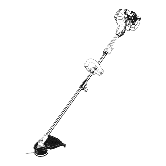
- Page 6 Section 2 KnowYourUnit Applications With the optional brushcutter accessory kit: As a trimmer: Cutting weeds and light bush of up to 1/2 inch in diameter Cutting grass and light weeds Edging Spark Plug. Starter Rope Grip Decorative trimming around trees, fences, etc. Fuel Cap Throttle Control...
- Page 7 Section 3 Assembly Install and Adjust the D-handle Shaft Grip Remove the screws and bottom ciamp piece that (4) Screws =_ were installed on the D-handle for shipping. Shaft Housing Place D-handle over the shaft housing and onto the bottom clamp (Fig. 3-1). Place it a minimum of 6 inches (15.24 cm) from the end of the shaft grip.
- Page 8 Section 4 Oiland Fuel For proper engine operation and maximum reliability, pay strict attention to the oil and fuel mixing instructions on the 2-cycle oil container. Using improperly mixed fuel can severely damage the engine. UNLEADED GAS ° 2 C¥CI-E OI1- Thoroughly mix the proper ratio of 2-cycle engine oil i GALLON US 3i2 FL OZ...
- Page 9 Section 5 Operation P)iii OperateithisunitQn_inawe!!_venti!atedo_doQrar_i carbonmonoxideexhaustfumescanbelethal;ina c_nfinediiareaiiiiiiiiiiiiiiiiiiiiiiiiiiiiiiiiiiiiiiiiiiiiiiiiiiiiiiiiiiiiiiiiiiiiiiiiiiiiiiiiiiiiiiiiiiiiiiiiiiiiiiiiiiiiiiiiiiiiiiiiiiiiiiiiiiiiiiiiiiiiiiiiiiiiiiiii On/Off Stop Control Avoid ac_idental startingi Make sure you are in the S_rting positi_n when puiiing the sta_er rope (Figi s_3) i To avoid serious injury, the operator and unit must be inastable poSit iO_ Whiie start in9 Make SUre that a_ add;-On item is instalied...
- Page 10 Operation(continued) Read and understand the operator's manual for each add-on prior to operation. Removing the Cutting Attachment or Add-0ns [urn the knob counterclockwise to loosen (Fig. 5-4). Press and hold the release button (Fig. 5-4). 3. While firmly holding the upper shaft housing, puil the cutting attachment or add-on straight out of the EZ-Link _Mcoupier (Fig.
- Page 11 Operation(continued) Each time the head is bumped, about 1 inch (25.4 mm) of trimming line releases. A blade in the cutting attachment shield wiii cut the line to the proper length if any excess line is released. For best resuIts, tap the bump knob on bare ground or hard soil.
- Page 12 Section 6 Maintenance Maintenance Schedule NOTE: Maintenance, replacement or repair of the emission control devices and system may be Perform these required maintenance procedures at the performed by any non-read engine repair frequency statedin the table, lhese procedures should establishmen_ individual or authorized also be a part of any seasonal tune-up.
- Page 13 Maintenance (continued) Winding the Existing Inner Reel Hold the outer spooi with one hand and unscrew the Indexing Teeth Bump Knob clockwise (Fig. 6-1). Inspect the bolt inside the Bump Knob to make sure it moves freety. Replace the Bump Knob if damaged. Remove the inner reel from the outer spool (Fig.
- Page 14 Maintenance (continued) 12. insert the ends of the Iine into the two holding slots (Fig. 6-7). 13. insert the ends of the iine through the eyelets in the outer spooi and piace inner reel with spring inside the outer spooi (Fig. 6-8). Push the inner reet and outer spool together.
- Page 15 Maintenance (continued) Air Filter Maintenance Cleaning the Air Filter Carburetor/Air To avoid serious personal injury, always turn your Filter Cover trimmer off and allow it to cool before you clean or service it. Clean and re-oit the air filter every 10 hours of operation. It is an important item to maintain.
- Page 16 Maintenance (continued) Check Fuel Mixture Otd and/or improperly mixed fuel is usualIy the reason for improper unit performance. Drain and refitl the tank with fresh, properly mixed fuet prior to making any adjustments. Refer to Oil and Fuel Information, Clean Air Filter The condition of the air filter is important to the operation of the unit.
- Page 17 Maintenance (continued) Storage • Never store the unit with fuet in the tank where fumes may reach an open flame or spark. • Atlow the engine to cool before storing. • Store the unit locked up to prevent unauthorized use or damage.
- Page 18 Section 7 Troubleshooting CAUSE ACTION On/Off stop control is in the OFF position Turn the on/off stop control to ON Empty fuel tank Fill fuel tank with properly mixed fuel Primer bulb wasn't pressed enough Press primer bulb fully and siowiy 10 times Engine is flooded Squeeze the trigger, put lever in Position 2 and pull the starter rope...
- Page 19 Section 8 Specifications Engine Fype ............................Air-Cooled, 2-Cycle Stroke ..............................1.25 in. (31.75 mm) Displacement ............................. 1.4 cu in. (25 cc) Clutch Type ................................. Centrifugal idle Speed RPM ............................2,400 - 3,600 rpm Operating RPM ..............................7,000+ rpm ignition Tiype ................................Electronic ignition Switch ..............................
- Page 20 Notes zoiiiiiiiiiiii...
- Page 22 Notes ZZiiiiiii...
- Page 23 • In order to file a claim, go to your nearest Authorized Cub Cadet Service Center. Warranty services or repairs wilt be provided at all Authorized Cub Cadet Service Centers.
- Page 24 ENGINE PARTS - MODEL CC3075 2-CYCLE GAS TRIMMER PPN 41ADC75C010 Item Part No. Description • @ @ 753-04015 Cylinder 753-04016 Cylinder Base Gaskel Bolt 791-181706 Item Part Description 791-181707 Insulator 791-181079 Pull Handle 791-181708 Insulator Gasket 791-182118 Pulley Assembly (includes 43-45) 791-181709 Carburetor Gasket...
- Page 25 BOOM AND TRIMMER PARTS - CC3075 2-CYCLE GAS TRIMMER PPN 41ADC75C010 Item Part Description 791-180866 Grip 791-181688 Throttle Cable Assembly 791-180975 Throttle Trigger 791-610314 Throttle Trigger Spring 791-181689 Throttle Trigger Assembly (includes 3 & 4) 791-180252 Switch Assembly 791-181690 Wire Lead Assembly 791-610327 Shoulder Harness Clamp 753-1151...
- Page 26 No implied warranty, including any implied warranty The limited warranty set forth below is given bY Cub Cadet merchantability or fitness for a particular purpose, LLC with respect to new merchandise 15urchased and used applies after the applicable period of express written in the United States, its possessions and territories.