Dell PowerEdge R520 Owner's Manual
Owner's manual
Hide thumbs
Also See for PowerEdge R520:
- Owner's manual (141 pages) ,
- Technical manual (51 pages) ,
- Getting started manual (9 pages)

Related Manuals for Dell PowerEdge R520


Summary of Contents for Dell PowerEdge R520
- Page 1 Dell PowerEdge R520 Owner's Manual Regulatory Model: E19S Series Regulatory Type: E19S001...
-
Page 2: Notes, Cautions, And Warnings
Information in this publication is subject to change without notice. © 2012 Dell Inc. All rights reserved. Reproduction of these materials in any manner whatsoever without the written permission of Dell Inc. is strictly forbidden. Trademarks used in this text: Dell... -
Page 3: Table Of Contents
Contents Notes, Cautions, and Warnings....................2 1 About Your System........................9 ........................9 Front-Panel Features And Indicators ..............................11 LCD Panel Features ..............................11 Home Screen ..............................12 Setup Menu ...............................12 View Menu ..........................13 Hard-Drive Indicator Patterns ........................14 Back-Panel Features And Indicators ..............................15 NIC Indicator Codes ............................15 Power Indicator Codes ...................17... - Page 4 ....................30 Operating With A Setup Password Enabled ...........................30 Entering The UEFI Boot Manager ......................31 Using The Boot Manager Navigation Keys ............................31 Boot Manager Screen ...............................32 UEFI Boot Menu ..........................32 Embedded System Management ..............................32 iDRAC Settings Utility ........................32 Entering The iDRAC Settings Utility 3 Installing System Components....................33 ..............................33 Recommended Tools...
- Page 5 ............................53 Optical Drive (Optional) ..........................53 Removing The Optical Drive ..........................54 Installing The Optical Drive ................................54 Cooling Fans ...........................54 Removing A Cooling Fan ............................55 Installing A Cooling Fan ........................56 Internal USB Memory Key (Optional) ........................56 Replacing the Internal USB Key ......................57 Expansion Cards And Expansion-Card Risers ......................57 Expansion-Card Installation Guidelines...
- Page 6 Troubleshooting An Internal USB Key ..........................104 Troubleshooting An SD Card .........................105 Troubleshooting An Optical Drive ..........................105 Troubleshooting A Hard Drive ........................106 Troubleshooting A Storage Controller ........................106 Troubleshooting Expansion Cards ..........................107 Troubleshooting Processors 5 Using System Diagnostics.....................109 ............................109 Dell Online Diagnostics...
- Page 7 ........................109 Dell Embedded System Diagnostics ..................109 When To Use The Embedded System Diagnostics ....................109 Running The Embedded System Diagnostics ...........................110 System Diagnostic Controls 6 Jumpers And Connectors......................111 ..........................111 System Board Jumper Settings ............................112 System Board Connectors ..........................113 Disabling A Forgotten Password 7 Technical Specifications.......................115...
-
Page 9: About Your System
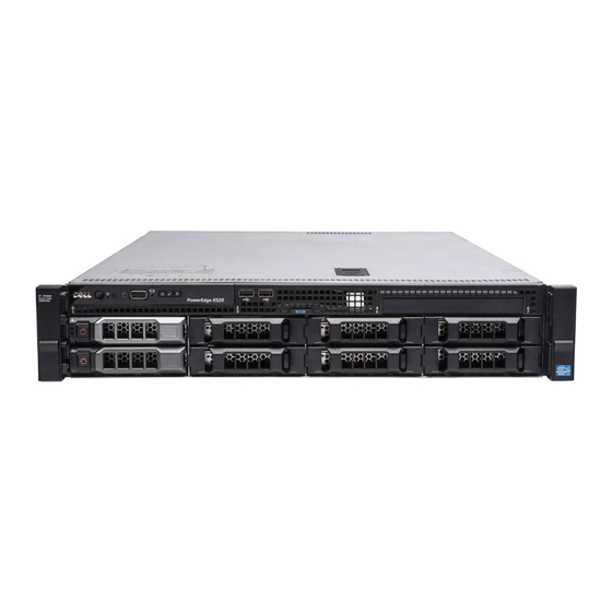
About Your System Front-Panel Features And Indicators Figure 1. Front-Panel Features and Indicators Figure 2. Front-Panel Features and Indicators for a Software RAID System Item Indicator, Button, or Icon Description Connector Power-on indicator, power The power-on indicator lights when the system power is button on. - Page 10 Item Indicator, Button, or Icon Description Connector Use this button only if directed to do so by qualified support personnel or by the operating system's documentation. System identification button The identification buttons on the front and back panels can be used to locate a particular system within a rack. When one of these buttons is pushed, the LCD panel on the front and the system status indicator on the back flashes blue until one of the buttons is pushed again.
-
Page 11: Lcd Panel Features
LCD Panel Features The system's LCD panel provides system information and status and error messages to indicate when the system is operating correctly or when the system needs attention. See LCD Error Messages for information about specific error codes. • The LCD backlight lights blue during normal operating conditions and lights amber to indicate an error condition. -
Page 12: Setup Menu
From the Home screen, press the Select button to enter the main menu. Setup Menu NOTE: When you select an option in the Setup menu, you must confirm the option before proceeding to the next action. Option Description iDRAC Select DHCP or Static IP to configure the network mode. If Static IP is selected, the available fields are IP, Subnet (Sub), and Gateway (Gtw). -
Page 13: Hard-Drive Indicator Patterns
Hard-Drive Indicator Patterns Figure 4. Hard-Drive Indicators 1. hard-drive activity indicator (green) 2. hard-drive status indicator (green and amber) NOTE: If the hard drive is in Advanced Host Controller Interface (AHCI) mode, the status indicator (on the right side) does not function and remains off. Drive-Status Indicator Pattern (RAID Only) Condition Blinks green two times per second... -
Page 14: Back-Panel Features And Indicators
Back-Panel Features And Indicators Figure 5. Back-Panel Features and Indicators—Redundant Power Supply Unit Chassis Figure 6. Back-Panel Features and Indicators—Non-Redundant Power Supply Unit Chassis Item Indicator, Button, or Icon Description Connector PCIe expansion card slot 1 Connects a PCI Express expansion card. vFlash media card slot Allows you to insert a vFlash media card. -
Page 15: Nic Indicator Codes
Item Indicator, Button, or Icon Description Connector the front and the system status indicator on the back blink until one of the buttons is pushed again. Press to toggle the system ID on and off. If the system hangs during POST, press and hold the system ID button for more than five seconds to enter BIOS progress mode. - Page 16 Figure 8. AC Power Supply Status Indicator 1. AC power supply status indicator/handle Figure 9. DC Power Supply Status Indicator 1. DC power supply status indicator Power Condition Indicator Pattern Not lit Power is not connected. Green The handle/LED indicator lights green indicating that a valid power source is connected to the power supply and that the power supply is operational.
-
Page 17: Power Indicator Codes For Non-Redundant Power Supply
Power Condition Indicator Pattern CAUTION: AC power supplies support both 220 V and 110 V input voltages. When two identical power supplies receive different input voltages, they can output different wattages, and trigger a mismatch. CAUTION: If two power supplies are used, they must be of the same type and have the same maximum output power. -
Page 18: Other Information You May Need
• For the full name of an abbreviation or acronym used in this document, see the Glossary at support.dell.com/ manuals. NOTE: Always check for updates on support.dell.com/manuals and read the updates first because they often... -
Page 19: Using The System Setup And Boot Manager
Enters the System Setup. <F10> Enters System Services, which opens the Dell Lifecycle Controller 2 (LC2). The Dell LC2 supports systems management features such as operating system deployment, hardware diagnostics, platform updates, and platform configuration, using a graphical user interface. The exact LC2 feature set is determined by the iDRAC license purchased. -
Page 20: Entering System Setup
NOTE: Operating systems must be UEFI-compatible to be installed from the UEFI boot mode. DOS and 32-bit operating systems do not support UEFI and can only be installed from the BIOS boot mode. NOTE: For the latest information on supported operating systems, go to dell.com/ossupport. Entering System Setup Turn on or restart your system. -
Page 21: System Setup Main Screen
System Setup Main Screen NOTE: Press <Alt><F> to reset the BIOS or UEFI settings to their default settings. Menu Item Description System BIOS This option is used to view and configure BIOS settings. iDRAC Settings This option is used to view and configure iDRAC settings. Device Settings This option is used to view and configure device settings. -
Page 22: Memory Settings Screen
Menu Item Description System Service Tag Displays the system Service Tag. System Manufacturer Displays the name of system manufacturer. System Manufacturer Contact Information Displays the contact information of the system manufacturer. Memory Settings Screen Menu Item Description System Memory Size Displays the amount of memory installed in the system. -
Page 23: Sata Settings Screen
Menu Item Description Virtualization Technology Allows you to enable or disable the additional hardware capabilities provided for virtualization. By default, the Virtualization Technology option is set to Enabled. Adjacent Cache Line Allows you to optimize the system for applications that require high utilization of sequential Prefetch memory access. -
Page 24: Boot Settings Screen
Boot Settings Screen Menu Item Description Boot Mode Allows you to set the boot mode of the system. CAUTION: Switching the boot mode may prevent the system from booting if the operating system is not installed in the same boot mode. If the operating system supports UEFI, you can set this option to UEFI. -
Page 25: Serial Communications Screen
Menu Item Description Internal SD Card If set to Mirror mode, data is written on both SD cards. If any one of the SD card fails, data is Redundancy written to the active SD card. Data from this card is copied to the replacement SD card at the next boot. -
Page 26: System Profile Settings Screen
Custom. By default, the System Profile option is set to Performance Per Watt Optimized (DAPC). DAPC is Dell Active Power Controller. NOTE: The following parameters are available only when the System Profile is set to Custom. -
Page 27: System Security Screen
BIOS updates, it is recommended to set this field to Disabled. By default, the BIOS Update Control option is set to Unlocked. NOTE: BIOS updates using Dell Update Package are not affected by this option. Power Button Allows you to enable or disable the power button on the front of the system. -
Page 28: Miscellaneous Settings
Miscellaneous Settings Menu Item Description System Time Allows you to set the time on the system. System Date Allows you to set the date on the system. Asset Tag Displays the asset tag and allows you to modify it for security and tracking purposes. Keyboard NumLock Allows you to set whether the system boots with the NumLock enabled or disabled. -
Page 29: Deleting Or Changing An Existing System And/Or Setup Password
To enter System Setup, press <F2> immediately after a power-on or reboot. In the System Setup Main Menu, select System BIOS and press <Enter>. The System BIOS screen is displayed. In the System BIOS screen, select System Security and press <Enter>. The System Security screen is displayed. -
Page 30: Using Your System Password To Secure Your System
Using Your System Password To Secure Your System NOTE: If you have assigned a setup password, the system accepts your setup password as an alternate system password. Turn on or reboot your system. Type your password and press <Enter>. When Password Status is Locked, type the password and press <Enter> when prompted at reboot. If an incorrect system password is entered, the system displays a message and prompts you to re-enter your password. -
Page 31: Using The Boot Manager Navigation Keys
Displays a list of the drivers installed on the system and their health status. Launch System Enables you to access the System Setup. Setup System Utilities Enables you to access the BIOS Update File Explorer, run the Dell Diagnostics program, and reboot the system. -
Page 32: Uefi Boot Menu
Sets a one-time boot option not included in the boot option list. Embedded System Management The Dell Lifecycle Controller provides advanced embedded systems management throughout the server’s lifecycle. The Lifecycle Controller can be started during the boot sequence and can function independently of the operating system. -
Page 33: Installing System Components
Installing System Components Recommended Tools You may need the following items to perform the procedures in this section: • Key to the system keylock • #1 and #2 Phillips screwdrivers • T10 and T15 Torx screwdrivers • Wrist grounding strap connected to ground Following tools are required for assembling cables for a DC power supply unit (PSU), when available: •... -
Page 34: Removing The Front Bezel
Damage due to servicing that is not authorized by Dell is not covered by your warranty. Read and follow the safety instructions that came with the product. -
Page 35: Closing The System
Damage due to servicing that is not authorized by Dell is not covered by your warranty. Read and follow the safety instructions that came with the product. - Page 36 Figure 13. Inside the System—Redundant Power Supply Unit Chassis 1. cooling shroud 10. cooling fans (6) 2. expansion-card latch 11. optical drive (optional) 3. power supply (redundant) 12. hard drives (8) 4. expansion-card riser 2 13. information tag 5. expansion card 14.
-
Page 37: Cooling Shroud
Figure 14. Inside the System—Non-Redundant Power Supply Unit Chassis 1. cooling shroud 9. DIMMs (12) 2. expansion-card latch 10. cooling fans (6) 3. power supply (non-redundant) 11. optical drive (optional) 4. expansion-card riser 2 12. hard drives (8) 5. expansion card 13. -
Page 38: Removing The Cooling Shroud
Damage due to servicing that is not authorized by Dell is not covered by your warranty. Read and follow the safety instructions that came with the product. -
Page 39: Installing The Cooling Shroud
Damage due to servicing that is not authorized by Dell is not covered by your warranty. Read and follow the safety instructions that came with the product. - Page 40 The system contains 12 memory sockets split into two sets of six sockets, one set per processor. Each six-socket set is organized into three channels. In each channel, the release levers of the first socket is marked white and the second black.
-
Page 41: General Memory Module Guidelines
General Memory Module Guidelines This system supports Flexible Memory Configuration, enabling the system to be configured and run in any valid chipset architectural configuration. The following are the recommended guidelines for best performance: • UDIMMs and RDIMMs must not be mixed. •... -
Page 42: Memory Optimized (Independent Channel) Mode
NOTE: Advanced ECC with mirroring is not supported. Memory Optimized (Independent Channel) Mode This mode supports SDDC only for memory modules that use x4 device width and does not impose any specific slot population requirements. Memory Sparing NOTE: To use memory sparing, this feature must be enabled in the System Setup. In this mode, one rank per channel is reserved as a spare. - Page 43 System Capacity DIMM Size (in Number of Organization and DIMM Slot Population (in GB) DIMMs Speed 1R x8, 1600 MT/s 1R x8, 1333 MT/s A1, A2 1R x8, 1600 MT/s 1R x8, 1333 MT/s A1, A2, A3, A4, A5 1R x8, 1600 MT/s 1R x8, 1333 MT/s A1, A2, A3 1R x8, 1600 MT/s...
-
Page 44: Removing Memory Modules
Damage due to servicing that is not authorized by Dell is not covered by your warranty. Read and follow the safety instructions that came with the product. -
Page 45: Installing Memory Modules
Damage due to servicing that is not authorized by Dell is not covered by your warranty. Read and follow the safety instructions that came with the product. -
Page 46: Removing A 3.5 Inch Hard-Drive Blank
• up to four 3.5 inch or 2.5 inch hot-swappable hard drives for software RAID NOTE: On software RAID systems, slots 4 through 7 are not functional and are pre-installed with dual slot hard- drive blanks. All hard drives connect to the system board through the hard-drive backplane. Hot-swappable hard drives are supplied in hot-swappable hard-drive carriers that fit in the hard-drive slots. -
Page 47: Removing A Dual Slot Hard-Drive Blank
If applicable, install the front bezel. Figure 19. Hard-Drive Blank Installation Sequence Removing A Dual Slot Hard-Drive Blank CAUTION: To maintain proper system cooling, all empty hard-drive slots must have hard-drive blanks installed. NOTE: Systems configured for software RAID support only four hard drives. The remaining hard-drive slots are pre- installed with dual slot hard-drive blanks, and are not available for software RAID. -
Page 48: Installing A Dual Slot Hard-Drive Blank
Figure 20. Removing and Installing A Dual Slot Hard-Drive Blank 1. dual slot hard-drive blank 2. release tabs (2) Installing A Dual Slot Hard-Drive Blank If installed, remove the front bezel. Insert the dual slot hard-drive blank into the hard-drive slot, and push it until the release tabs click into place. If applicable, install the front bezel. -
Page 49: Installing A Hot-Swap Hard Drive
Damage due to servicing that is not authorized by Dell is not covered by your warranty. Read and follow the safety instructions that came with the product. -
Page 50: Removing A 2.5 Inch Hard Drive From A 3.5 Inch Hard-Drive Adapter
Damage due to servicing that is not authorized by Dell is not covered by your warranty. Read and follow the safety instructions that came with the product. - Page 51 Figure 23. Removing and Installing a Hot-Swap Hard Drive Into a Hard-Drive Carrier 1. hard-drive carrier 2. screws (4) 3. hard drive 4. screw holes (4)
-
Page 52: Installing A Hard Drive Or A Hard-Drive Adapter Into A Hard-Drive Carrier
Damage due to servicing that is not authorized by Dell is not covered by your warranty. Read and follow the safety instructions that came with the product. -
Page 53: Optical Drive (Optional)
Damage due to servicing that is not authorized by Dell is not covered by your warranty. Read and follow the safety instructions that came with the product. -
Page 54: Installing The Optical Drive
Damage due to servicing that is not authorized by Dell is not covered by your warranty. Read and follow the safety instructions that came with the product. -
Page 55: Installing A Cooling Fan
Damage due to servicing that is not authorized by Dell is not covered by your warranty. Read and follow the safety instructions that came with the product. -
Page 56: Internal Usb Memory Key (Optional)
Damage due to servicing that is not authorized by Dell is not covered by your warranty. Read and follow the safety instructions that came with the product. -
Page 57: Expansion Cards And Expansion-Card Risers
Figure 27. Replacing the Internal USB Key 1. USB memory key connector 2. USB memory key Expansion Cards And Expansion-Card Risers NOTE: A missing or an unsupported expansion-card riser logs an SEL event. It does not prevent your system from powering on and no BIOS POST message or F1/F2 pause is displayed. -
Page 58: Removing An Expansion Card
Damage due to servicing that is not authorized by Dell is not covered by your warranty. Read and follow the safety instructions that came with the product. - Page 59 Figure 28. Removing and Installing the Expansion Card from Expansion-Card Riser 1 1. expansion card 2. expansion-card latch 3. riser 1...
-
Page 60: Installing An Expansion Card
Damage due to servicing that is not authorized by Dell is not covered by your warranty. Read and follow the safety instructions that came with the product. -
Page 61: Removing Expansion-Card Risers
Damage due to servicing that is not authorized by Dell is not covered by your warranty. Read and follow the safety instructions that came with the product. -
Page 62: Installing Expansion-Card Risers
Damage due to servicing that is not authorized by Dell is not covered by your warranty. Read and follow the safety instructions that came with the product. -
Page 63: Removing The Idrac Ports Card
Damage due to servicing that is not authorized by Dell is not covered by your warranty. Read and follow the safety instructions that came with the product. -
Page 64: Installing The Idrac Ports Card
Damage due to servicing that is not authorized by Dell is not covered by your warranty. Read and follow the safety instructions that came with the product. -
Page 65: Sd Vflash Card
A vFlash SD card is a Secure Digital (SD) card that plugs into the vFlash SD card slot in the system. It provides persistent on-demand local storage and a custom deployment environment that allows automation of server configuration, scripts, iDRAC7 User's Guide at support.dell.com/ and imaging. It emulates USB device(s). For more information, see the manuals. -
Page 66: Removing The Internal Dual Sd Module
Damage due to servicing that is not authorized by Dell is not covered by your warranty. Read and follow the safety instructions that came with the product. -
Page 67: Installing The Internal Dual Sd Module
Damage due to servicing that is not authorized by Dell is not covered by your warranty. Read and follow the safety instructions that came with the product. -
Page 68: Integrated Storage Controller Card
Damage due to servicing that is not authorized by Dell is not covered by your warranty. Read and follow the safety instructions that came with the product. -
Page 69: Installing The Integrated Storage Controller
Damage due to servicing that is not authorized by Dell is not covered by your warranty. Read and follow the safety instructions that came with the product. -
Page 70: Processors
Damage due to servicing that is not authorized by Dell is not covered by your warranty. Read and follow the safety instructions that came with the product. - Page 71 Figure 36. Removing and Installing the Heat Sink 1. retention sockets (4) 2. heat sink 3. retention screws (4) CAUTION: The processor is held in its socket under strong pressure. Be aware that the release lever can spring up suddenly if not firmly grasped. Position your thumb firmly over the processor socket-release lever and release the lever from the locked position.
-
Page 72: Installing A Processor
Damage due to servicing that is not authorized by Dell is not covered by your warranty. Read and follow the safety instructions that came with the product. -
Page 73: Power Supplies
NOTE: You can update the system BIOS using the Lifecycle Controller. Turn off the system, including any attached peripherals, and disconnect the system from the electrical outlet. When disconnected from power, press and hold the power button for three seconds to fully drain the system of stored power prior to removing the cover. -
Page 74: Removing An Ac Power Supply
Damage due to servicing that is not authorized by Dell is not covered by your warranty. Read and follow the safety instructions that came with the product. -
Page 75: Installing An Ac Power Supply
DC power and to safety grounds. Do not attempt connecting to DC power or installing grounds yourself. All electrical wiring must comply with applicable local or national codes and practices. Damage due to servicing that is not authorized by Dell is not covered by your warranty. Read and follow all safety instructions that came with the product. - Page 76 DC power and to safety grounds. Do not attempt connecting to DC power or installing grounds yourself. All electrical wiring must comply with applicable local or national codes and practices. Damage due to servicing that is not authorized by Dell is not covered by your warranty. Read and follow all safety instructions that came with the product.
- Page 77 DC power and to safety grounds. Do not attempt connecting to DC power or installing grounds yourself. All electrical wiring must comply with applicable local or national codes and practices. Damage due to servicing that is not authorized by Dell is not covered by your warranty. Read and follow all safety instructions that came with the product.
-
Page 78: Removing A Dc Power Supply
DC power and to safety grounds. Do not attempt connecting to DC power or installing grounds yourself. All electrical wiring must comply with applicable local or national codes and practices. Damage due to servicing that is not authorized by Dell is not covered by your warranty. Read and follow all safety instructions that came with the product. -
Page 79: Installing A Dc Power Supply
DC power and to safety grounds. Do not attempt connecting to DC power or installing grounds yourself. All electrical wiring must comply with applicable local or national codes and practices. Damage due to servicing that is not authorized by Dell is not covered by your warranty. Read and follow all safety instructions that came with the product. -
Page 80: Installing The Power Supply Blank
Damage due to servicing that is not authorized by Dell is not covered by your warranty. Read and follow the safety instructions that came with the product. - Page 81 Figure 43. Removing and Installing the Power-Distribution Board 1. power-distribution board 5. release tab 2. fan 6 cable connector 6. power-distribution board connector 3. screws (4) 4. power-interposer board...
- Page 82 Figure 44. Power-Distribution Board Connectors 1. fan 6 cable connector 2. power-distribution board connector 3. 8-pin power connector...
-
Page 83: Installing The Power-Distribution And Power-Interposer Boards
Damage due to servicing that is not authorized by Dell is not covered by your warranty. Read and follow the safety instructions that came with the product. -
Page 84: Removing A Non-Redundant Power Supply
Damage due to servicing that is not authorized by Dell is not covered by your warranty. Read and follow the safety instructions that came with the product. -
Page 85: Installing A Non-Redundant Power Supply
Damage due to servicing that is not authorized by Dell is not covered by your warranty. Read and follow the safety instructions that came with the product. -
Page 86: Removing The Redundant Power Supply Unit Divider
Damage due to servicing that is not authorized by Dell is not covered by your warranty. Read and follow the safety instructions that came with the product. -
Page 87: Installing The Redundant Power Supply Unit Divider
Damage due to servicing that is not authorized by Dell is not covered by your warranty. Read and follow the safety instructions that came with the product. -
Page 88: System Battery
Damage due to servicing that is not authorized by Dell is not covered by your warranty. Read and follow the safety instructions that came with the product. -
Page 89: Hard-Drive Backplane
Damage due to servicing that is not authorized by Dell is not covered by your warranty. Read and follow the safety instructions that came with the product. - Page 90 Figure 49. Removing and Installing the Hard-Drive Backplane 1. securing hooks 6. backplane power connector 2. securing slot 7. SAS B connector 3. release tabs (2) 8. hard-drive backplane 4. SAS A connector 9. hard-drive connectors (8) 5. backplane signal connector...
- Page 91 Figure 50. Cabling Diagram of the Hard-Drive Backplane for a Redundant PSU System 1. system board 6. SAS A cable connector 2. hard-drive backplane 7. cable routing guide 3. SAS B cable connector 8. power distribution board 4. power cable connector 9.
-
Page 92: Installing The Hard-Drive Backplane
Damage due to servicing that is not authorized by Dell is not covered by your warranty. Read and follow the safety instructions that came with the product. -
Page 93: Control Panel Assembly
Damage due to servicing that is not authorized by Dell is not covered by your warranty. Read and follow the safety instructions that came with the product. -
Page 94: Installing The Control-Panel Board
Damage due to servicing that is not authorized by Dell is not covered by your warranty. Read and follow the safety instructions that came with the product. -
Page 95: Installing The Control Panel
Damage due to servicing that is not authorized by Dell is not covered by your warranty. Read and follow the safety instructions that came with the product. -
Page 96: Removing The System Board
Damage due to servicing that is not authorized by Dell is not covered by your warranty. Read and follow the safety instructions that came with the product. -
Page 97: Installing The System Board
Damage due to servicing that is not authorized by Dell is not covered by your warranty. Read and follow the safety instructions that came with the product. - Page 98 If applicable, install the front bezel. 10. Reconnect the system to its electrical outlet and turn the system on, including any attached peripherals. iDRAC7 User's Guide , at 11. Import your new or existing iDRAC Ports license. For more information, see support.dell.com/manuals.
-
Page 99: Troubleshooting Your System
Damage due to servicing that is not authorized by Dell is not covered by your warranty. Read and follow the safety instructions that came with the product. -
Page 100: Troubleshooting A Serial I/O Device
Damage due to servicing that is not authorized by Dell is not covered by your warranty. Read and follow the safety instructions that came with the product. -
Page 101: Troubleshooting A Damaged System
Damage due to servicing that is not authorized by Dell is not covered by your warranty. Read and follow the safety instructions that came with the product. -
Page 102: Troubleshooting The System Battery
Damage due to servicing that is not authorized by Dell is not covered by your warranty. Read and follow the safety instructions that came with the product. -
Page 103: Troubleshooting Cooling Fans
Damage due to servicing that is not authorized by Dell is not covered by your warranty. Read and follow the safety instructions that came with the product. -
Page 104: Troubleshooting An Internal Usb Key
Damage due to servicing that is not authorized by Dell is not covered by your warranty. Read and follow the safety instructions that came with the product. -
Page 105: Troubleshooting An Optical Drive
Damage due to servicing that is not authorized by Dell is not covered by your warranty. Read and follow the safety instructions that came with the product. -
Page 106: Troubleshooting A Storage Controller
Damage due to servicing that is not authorized by Dell is not covered by your warranty. Read and follow the safety instructions that came with the product. -
Page 107: Troubleshooting Processors
Damage due to servicing that is not authorized by Dell is not covered by your warranty. Read and follow the safety instructions that came with the product. -
Page 109: Using System Diagnostics
Dell Online Diagnostics Dell Online Diagnostics, a stand-alone suite of diagnostic programs or test modules, allows you to run diagnostic tests on the systems in a production environment, and helps you ensure maximum uptime of your systems. Online Diagnostics allows you to run diagnostic tests on chassis and storage components such as hard drives, physical memory, and network interface cards (NICs). -
Page 110: System Diagnostic Controls
Displays a time-stamped log of the results of all tests run on the system. This is displayed if at least one event description is recorded. Dell Enhanced Pre-boot System Assessment User Guide at For information about embedded system diagnostics, see the... -
Page 111: Jumpers And Connectors
Jumpers And Connectors System Board Jumper Settings For information on resetting the password jumper to disable a password, see Disabling A Forgotten Password. Table 5. System Board Jumper Settings Jumper Setting Description PWRD_EN The password feature is enabled (pins 2–4). (default) The password feature is disabled (pins 4–6). -
Page 112: System Board Connectors
System Board Connectors Figure 54. System Board Connectors and Jumpers Item Connector Description INT_STORAGE Storage controller card connector ID_BTN System identification button CMA_JACK System identification connector USB 2 USB connector USB 1 USB connector IO_RISER2 Riser 2 connector NIC2 Network connector NIC1 Network connector Video connector... -
Page 113: Disabling A Forgotten Password
Damage due to servicing that is not authorized by Dell is not covered by your warranty. Read and follow the safety instructions that came with the product. - Page 114 Open the system. Move the jumper on the system-board jumper from pins 2 and 4 to pins 4 and 6. Close the system. 10. Reconnect the system to its electrical outlet and turn the system on, including any attached peripherals. 11.
-
Page 115: Technical Specifications
Technical Specifications Processor Processor type One or two Intel Xeon processor E5-2400 product family Expansion Bus Bus type PCI Express Generation 2 and Generation 3 Expansion slots using riser card for a one processor system: Riser 1 (Slot 1) One half-height, half-length x4 link with x8 slot Riser 2 (Slot 2) One full-height, full-length x8 link with x16 slot (Slot 3) One full-height, half-length x4 link with x8 slot... - Page 116 Memory Minimum RAM 2 GB (single processor configuration) Maximum RAM 192 GB Drives Up to eight 3.5 inch or 2.5 inch, internal, hot-swappable Hard drives SAS, SATA, SAS SSD. SATA SSD, or Nearline SAS hard drives in hard-drive slots 0 through 7. Up to four 3.5 inch or 2.5 inch, internal, hot-swappable SAS, SATA, SAS SSD, SATA SSD, or Nearline SAS hard drives in hard-drive slots 0 through 3 for a software RAID...
- Page 117 • Non-redundant power supplies are not supported. • Non Dell qualified peripheral cards and/or peripheral cards are not supported. Storage Temperature –40 °C to 65 °C (–40 °F to 149 °F) with a maximum temperature gradation of 20 °C per hour.
-
Page 119: System Messages
System Messages LCD Messages NOTE: Applicable only if your system has an LCD display. The LCD messages consist of brief text messages that refer to events recorded in the System Event Log (SEL). For information on the SEL and configuring system management settings, see the systems management software documentation. - Page 120 Error Code Message Information AMP0302 Message The system board < name > current is greater than the upper warning threshold. name > current is outside of the optimum range. Details System board < Action 1. Review system power policy. 2. Check system logs for power related failures. 3.
- Page 121 Error Code Message Information BAT0002 Message The system board battery has failed. LCD Message The system board battery has failed. Check battery. Details The system board battery is either missing or bad. Action Getting Help. BAT0017 name > battery has failed. Message The <...
- Page 122 Error Code Message Information CPU0204 Message CPU < number > < name > voltage is outside of range. number > < name > voltage is outside of range. Re-seat CPU. LCD Message CPU < Details Voltages outside the allowable range may damage electrical components or may cause the system to shutdown.
- Page 123 Error Code Message Information 4. Reapply input power and turn on the system. 5. If the issue persists, see Getting Help. CPU0703 Message CPU bus initialization error detected. LCD Message CPU bus initialization error detected. Power cycle system. Details System event log and operating system logs may indicate that the exception is external to the processor.
- Page 124 Error Code Message Information Details Fan has failed. Action Remove and reinstall failed fans or install additional fans. HWC1001 name > is absent. Message The < name > is absent. Check hardware. LCD Message The < Details The absent device may be necessary for proper operation. System functionality may be degraded.
- Page 125 Error Code Message Information Action Check the memory configuration. Re-seat the memory modules. If the issue persists, Getting Help. MEM0701 Message Correctable memory error rate exceeded for < location >. Details The memory may not be operational. This an early indicator of a possible future uncorrectable error.
- Page 126 Error Code Message Information Action Cycle input power, update component drivers, if device is removable, reinstall the device. PCI1308 Message A PCI parity error was detected on a component at bus < bus >device< device >function func >. < LCD Message PCI parity error on bus < bus >...
- Page 127 Error Code Message Information Action Remove and re-seat the failed disk. If the issue persists, see Getting Help. PDR1016 number > is removed from disk drive bay < bay >. Message Drive < number > removed from disk drive bay < bay >. Check drive. LCD Message Drive <...
- Page 128 Error Code Message Information LCD Message Power supply < number > is incorrectly configured. Check PSU. Details Power supplies should be of the same input type and power rating. Action Install matched power supplies and review proper configuration in this manual. PSU0016 number >...
- Page 129 Error Code Message Information PSU0035 Message An over voltage fault detected on power supply < number >. number >. Check PSU. LCD Message Over voltage fault on PSU < Action Check input power or reinstall the power supply. If the issue persists, see Getting Help.
- Page 130 Error Code Message Information Action Check the event log for power supply failures. Review system configuration and power consumption and upgrade or install power supplies accordingly. PWR1005 Message The system performance degraded because the user-defined power capacity has changed. Details The user-defined power settings have affected system operation.
- Page 131 Error Code Message Information Action Reinstall the SD module. RFM2004 name >. Message Failure detected on Internal Dual SD Module < name > failed. Check SD Card. LCD Message Internal Dual SD Module < Details The SD card module is installed but improperly configured or failed to initialize. Action Reinstall the SD module and remove and reinstall SD cards.
- Page 132 Error Code Message Information SEL1204 Message An unknown system hardware failure detected. LCD Message Unknown system hardware failure. Details If the system event log failed to initialize, platform status and failure events are not captured. Some management software do not report platform exceptions. Action Re-configure system to the minimum supported configuration.
-
Page 133: Warning Messages
Warning Messages A warning message alerts you to a possible problem and prompts you to respond before the system continues a task. For example, before you format a hard drive, a message warns you that you may lose all data on the hard drive. Warning messages usually interrupt the task and require you to respond by typing y (yes) or n (no). -
Page 135: Getting Help
Visit support.dell.com. Select your support category. If you are not a U.S. customer, select your country code at the bottom of the support.dell.com page, or select All to see more choices. Select the appropriate service or support link based on your need.