Table of Contents
Advertisement
Advertisement
Table of Contents

Related Manuals for Asus Rampage Extreme - Motherboard - ATX


Summary of Contents for Asus Rampage Extreme - Motherboard - ATX
- Page 1 Rampage Extreme...
- Page 2 Product warranty or service will not be extended if: (1) the product is repaired, modified or altered, unless such repair, modification of alteration is authorized in writing by ASUS; or (2) the serial number of the product is defaced or missing.
-
Page 3: Table Of Contents
Product highlights ............1-2 1.3.2 ROG Intelligent Performance & Overclocking features ... 1-5 1.3.3 ROG unique features ............1-7 1.3.4 ASUS special features ............ 1-8 Chapter 2: Hardware information Before you proceed ..............2-1 Motherboard overview ..............2-4 2.2.1 Motherboard layout ............2-4 2.2.2... -
Page 4: Contents
BIOS setup Managing and updating your BIOS ..........3-1 3.1.1 ASUS Update utility ............3-1 3.1.2 ASUS EZ Flash 2 utility ........... 3-4 3.1.3 AFUDOS utility ..............3-5 3.1.4 ASUS CrashFree BIOS 3 utility ........3-7 BIOS setup program ..............3-8 3.2.1... - Page 5 Boot Device Priority ............3-38 3.7.2 Boot Settings Configuration .......... 3-39 3.7.3 BIOS Boot Priority ............3-40 3.7.4 Security ................. 3-41 Tools menu ................. 3-43 3.8.1 ASUS EZ Flash 2 ............3-43 3.8.2 ASUS O.C. Profile ............3-44 3.8.3 AI NET 2................ 3-45...
- Page 6 ASUS MyLogo3™ ............4-9 4.3.2 AI NET 2.................4-11 4.3.3 Sound Blaster X-Fi audio utility ........4-12 4.3.4 ASUS PC Probe II ............4-16 4.3.5 ASUS EPU-6 Engine ............ 4-22 4.3.6 ASUS AI Suite ............... 4-26 4.3.7 ASUS AI Nap ..............4-28 4.3.8...
- Page 7 Contents Enhanced Intel SpeedStep Technology (EIST) ......A-1 ® A.2.1 System requirements ............A-1 A.2.2 Using the EIST ..............A-2 Intel Hyper-Threading Technology ...........A-3 ® Using the Hyper-Threading Technology ........A-3 Debug code table .................A-4...
-
Page 8: Notices
Notices Federal Communications Commission Statement This device complies with Part 15 of the FCC Rules. Operation is subject to the following two conditions: • This device may not cause harmful interference, and • This device must accept any interference received including interference that may cause undesired operation. -
Page 9: Safety Information
Safety information Electrical safety • To prevent electrical shock hazard, disconnect the power cable from the electrical outlet before relocating the system. • When adding or removing devices to or from the system, ensure that the power cables for the devices are unplugged before the signal cables are connected. -
Page 10: About This Guide
Refer to the following sources for additional information and for product and software updates. ASUS websites The ASUS website provides updated information on ASUS hardware and software products. Refer to the ASUS contact information. Optional documentation Your product package may include optional documentation, such as warranty flyers, that may have been added by your dealer. -
Page 11: Conventions Used In This Guide
Conventions used in this guide To make sure that you perform certain tasks properly, take note of the following symbols used throughout this manual. DANGER/WARNING: Information to prevent injury to yourself when trying to complete a task. CAUTION: Information to prevent damage to the components when trying to complete a task. -
Page 12: Rampage Extreme Specifications Summary
® less than 3GB. Hence, a total installed memory of less than 3 GB is recommended. ****Refer to www.asus.com or this user manual for the Memory QVL (Qualified Vendors Lists). Expansion Slots 2 x PCIe 2.0 x16 slots (�� full x16, x16 speed) (��... - Page 13 - AI Booster Utility - O.C. Profile Overclocking protection: - COP EX (Component Overheat Protection -EX) - Voltiminder LED - ASUS C.P.R. (CPU Parameter Recall) ROG Special Features Speeding HDD BIOS Flashback LCD Poster Onboard Switches: TweakIt / Power / Reset / Clr CMOS...
- Page 14 Optional Thermal Kit for NB and MOS SupremeFX X-Fi Audio Card LCD Poster ASUS Optional Fan DIY Pedestal 3 in 1 ASUS Q-connector kit UltraDMA 133/100/66 cable Floppy disk drive cable Serial ATA signal cables Serial ATA power cables 2-port USB2.0 + IEEE 1394a module...
- Page 15 Rampage Extreme specifications summary Software Support DVD: - Drivers and applications - ASUS PC Probe II - ASUS Update - ASUS AI Suite - Sound Blaster X-Fi utility - Futuremark 3DMark 06 Advanced Edition ® ® - Kaspersky Anti-virus software ®...
-
Page 17: Chapter 1: Product Introduction
This chapter describes the motherboard features and the new technologies it supports. Chapter 1: Product introduction... - Page 18 Chapter summary Welcome! ..................1-1 Package contents ................. 1-1 Special features ................1-2 ROG Rampage Extreme...
-
Page 19: Welcome
Thank you for buying an ROG Rampage Extreme motherboard! The motherboard delivers a host of new features and latest technologies, making it another standout in the long line of ASUS quality motherboards! Before you start installing the motherboard, and hardware devices on it, check the items in your package with the list below. -
Page 20: Special Features
Special features 1.3.1 Product highlights Republic of Gamers The Republic of Gamers consists only the best of the best. We offer the best hardware engineering, the fastest performance, the most innovating ideas, and we welcome the best gamers to join in. In the Republic of Gamers, mercy rules are only for the weak, and bragging rights means everything. - Page 21 PCIe 2.0 This motherboard supports the latest PCIe 2.0 device for twice the current speed and bandwidth. This enhances system performance while still providing backward compatibility to PCIe 1.0 devices. See page 2-19 for details. ATI CrossFireX™ Technology ATI’s CrossFireX™ boosts image quality along with rendering speed, eliminating the need to scale down screen resolutions to get the high image quality you want.
-
Page 22: High Definition Audio
Green ASUS This motherboard and its packaging comply with the European Union’s Restriction on the use of Hazardous Substances (RoHS). This is in line with the ASUS vision of creating environment-friendly and recyclable products/packaging to safeguard consumers’ health while minimizing the impact on the environment. -
Page 23: Rog Intelligent Performance & Overclocking Features
Extreme Engine even armed with high-performance ML- Caps, ensuring extra edge during extreme overclocking. With the power efficiency as high as 96%, ASUS ROG motherboards with the Extreme Engine produces less energy loss and less heat. The intelligent power phase can be changed on the fly, yielding even more heat dissipation. -
Page 24: Voltiminder Led
iROG iROG is a special IC which enables several ROG highlighted functions that give you full disposal of the motherboard at any stage! This design allows advanced user control and management to be processed at a hardware level. iROG greatly increases fun during overclocking for PC enthusiasts and it provides system maintenance and management with more control and efficiency. -
Page 25: Rog Unique Features
Loadline Calibration Maintaining ample voltage support for the CPU is critical during overclocking. The Loadline calibration ensures stable and optimal CPU voltage under heavy loading. It helps overclockers enjoy the motherboard’s ultimate OC capabilities and benchmark scores. 1.3.3 ROG unique features SupremeFX X-Fi features You may enjoy good quality sound from the thoughtful design of SupremeFX card on a hardware level. -
Page 26: Asus Special Features
Fanless Design—Stack Cool 2 ASUS Stack Cool 2 is a fan-less and zero-noise cooling solution that lowers the temperature of critical heat generating components. The motherboard uses a special design on the printed circuit board (PCB) to dissipate heat these critical components generate. -
Page 27: Asus Mylogo 3
See pages 2-39 and 2-44 for details. ASUS MyLogo 3 ASUS MyLogo 3 is a new feature present in the motherboard that allows you to personalize and add style to your system with customizable and animated boot logos. See page 3-39 for details. - Page 28 C.P.R. (CPU Parameter Recall) When the system hangs due to overclocking failure, there is no need to open the system chassis to clear CMOS data. Simply reboot the system, and the BIOS automatically restores the CPU default settings for each parameter. Due to the chipset behavior, AC power off is required before using C.P.R.
-
Page 29: Chapter 2: Hardware Information
This chapter lists the hardware setup procedures that you have to perform when installing system components. It includes description of the jumpers and connectors on the motherboard. Chapter 2: Hardware information... - Page 30 Chapter summary Before you proceed ..............2-1 Motherboard overview ..............2-4 Central Processing Unit (CPU) ........... 2-7 System memory ................. 2-13 Expansion slots ................2-17 Slide switch and jumper ............2-20 Connectors ................2-22 Installing accessories ..............2-39 Starting up for the first time ............2-47 2.10 Turning off the computer ............
-
Page 31: Before You Proceed
Before you proceed Take note of the following precautions before you install motherboard components or change any motherboard settings. • Unplug the power cord from the wall socket before touching any component. • Use a grounded wrist strap or touch a safely grounded object or a metal object, such as the power supply case, before handling components to avoid damaging them due to static electricity. - Page 32 Memory LED Refer to the illustration below for the location of the memory LED and the table below for LED definition. Normal (green) High (yellow) Crazy (red) DRAM Voltage 1.50–1.90 1.92–2.30 2.32– Northbridge/Southbridge LEDs The northbridge and southbridge LEDs each have two different voltage displays.
- Page 33 Hard Disk LED The hard disk LED is designed to indicate the hard disk activity. It blinks when data is being written into or read from the hard disk drive. The LED does not light up when there is no hard disk drive connected to the motherboard or when the hard disk drive does not function.
-
Page 34: Motherboard Overview
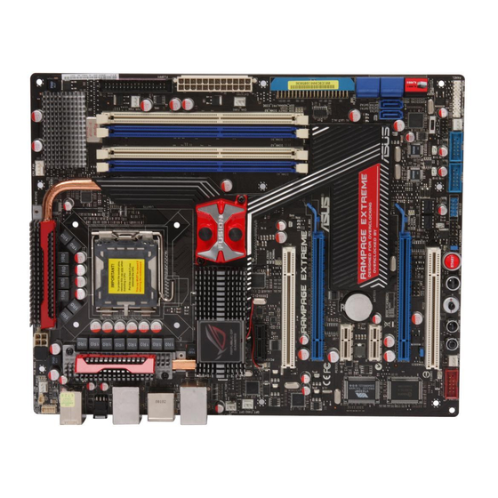
Motherboard overview 2.2.1 Motherboard layout 2.2.2 SupremeFX X-Fi audio card layout Refer to pages 2-22 and 2-31 for details UPREME about the audio jacks and connectors Listen with Absolutely HD on this card. Chapter 2: Hardware information... -
Page 35: Layout Contents
2.2.3 Layout contents Connectors/Jumpers/Switches/Slots Page CPU, chassis, and power fan connectors (4-pin CPU_FAN; 2-29 3-pin CHA_FAN1–3; 3-pin PWR_FAN; 3-pin OPT_FAN1–3) ATX power connectors (24-pin EATXPWR, 8-pin ATX12V) 2-32 LGA775 CPU Socket DDR3 DIMM slots 2-13 Floppy disk drive connector (34-1 pin FLOPPY) 2-24 IDE connector (40-1 pin PRI_EIDE) 2-25... -
Page 36: Placement Direction
2.2.4 Placement direction When installing the motherboard, make sure that you place it into the chassis in the correct orientation. The edge with external ports goes to the rear part of the chassis as indicated in the image below. 2.2.5 Screw holes Place nine (9) screws into the holes indicated by circles to secure the motherboard to the chassis. -
Page 37: Central Processing Unit (Cpu)
ASUS will shoulder the cost of repair only if the damage is shipment/transit-related. • Keep the cap after installing the motherboard. ASUS will process Return Merchandise Authorization (RMA) requests only if the motherboard comes with the cap on the LGA775 socket. -
Page 38: Installing The Cpu
2.3.1 Installing the CPU To install a CPU: Locate the CPU socket on the motherboard. Before installing the CPU, make sure that the cam box is facing towards you and the load lever is on your left. Press the load lever with your thumb Retention tab (A), then move it to the left (B) until it is released from the retention tab. - Page 39 Position the CPU over the socket, CPU notch making sure that the gold triangle is on the bottom-left corner of the socket then fit the socket alignment key into the CPU notch. The CPU fits in only one correct Gold orientation.
- Page 40 Close the load plate (A), then push the load lever (B) until it snaps into the retention tab. The motherboard supports Intel ® LGA775 processors with the Intel ® Enhanced Memory 64 Technology (EM64T), Enhanced Intel SpeedStep Technology ® (EIST), and Hyper-Threading Technology. Refer to the Appendix for more information on these CPU features.
-
Page 41: Installing The Cpu Heatsink And Fan
2.3.2 Installing the CPU heatsink and fan The Intel ® LGA775 processor requires a specially designed heatsink and fan assembly to ensure optimum thermal condition and performance. • When you buy a boxed Intel ® processor, the package includes the CPU fan and heatsink assembly. -
Page 42: Uninstalling The Cpu Heatsink And Fan
Connect the CPU fan cable to the connector on the motherboard labeled CPU_FAN. DO NOT forget to connect the CPU fan connector! Hardware monitoring errors can occur if you fail to plug this connector. 2.3.3 Uninstalling the CPU heatsink and fan To uninstall the CPU heatsink and fan: Disconnect the CPU fan cable from the connector on the motherboard. -
Page 43: System Memory
System memory 2.4.1 Overview The motherboard comes with four Double Data Rate 3 (DDR3) Dual Inline Memory Modules (DIMM) sockets. A DDR3 module has the same physical dimensions as a DDR2 DIMM but is notched differently. DDR3 modules are developed for better performance with less power consumption. - Page 44 • You may install varying memory sizes in Channel A and Channel B. The system maps the total size of the lower-sized channel for the dual-channel configuration. Any excess memory from the higher-sized channel is then mapped for single-channel operation. •...
-
Page 45: Memory Configuration
Dual-channel memory configuration. • C*: Supports four modules inserted into both the blue and white slots as two pairs of Dual-channel memory configuration. Visit the ASUS website for the latest DDR3-1600/1333/1067/800MHz QVL. ROG Rampage Extreme 2-15... -
Page 46: Installing A Dimm
2.4.3 Installing a DIMM Make sure to unplug the power supply before adding or removing DIMMs or other system components. Failure to do so may cause severe damage to both the motherboard and the components. To install a DIMM DDR3 DIMM notch Unlock a DDR3 DIMM socket by pressing the retaining clips outward. -
Page 47: Expansion Slots
Expansion slots In the future, you may need to install expansion cards. The following sub-sections describe the slots and the expansion cards that they support. Make sure to unplug the power cord before adding or removing expansion cards. Failure to do so may cause you physical injury and damage motherboard components. -
Page 48: Interrupt Assignments
2.5.3 Interrupt assignments Priority Standard function System timer Keyboard controller – Re-direct to IRQ#9 IRQ holder for PCI steering* Communications port (COM1)* IRQ holder for PCI steering* Floppy disk controller System CMOS/Real Time Clock IRQ holder for PCI steering* IRQ holder for PCI steering* IRQ holder for PCI steering* PS/2 compatible mouse port* Numeric data processor... -
Page 49: Pci Slots
2.5.4 PCI slots The PCI slots support cards such as a LAN card, SCSI card, USB card, and other cards that comply with PCI specifications. Refer to the figure below for the location of the slots. 2.5.5 PCI Express x1 slots This motherboard supports PCI Express x1 network cards, SCSI cards and other cards that comply with the PCI Express specifications. -
Page 50: Slide Switch And Jumper
Slide switch and jumper Clear RTC RAM (3-pin CLRTC_SW) This onboard slide switch allows you to enable the clr CMOS switch on the back I/O. You can clear the CMOS memory and system setup parameters by erasing the CMOS RTC RAM data. The clr CMOS switch on the back I/O helps you easily clear the system setup information such as system passwords. - Page 51 BIOS flash setting (6-pin BIOS_FLASHBACK) Two sets of BIOS Flash ROM (BIOS 1 and BIOS 2) are present on this motherboard. This jumper allows you to select either BIOS as the one to boot, or back up or restore BIOS content from one ROM to the other. Moving the jumper cap to pins 1-2 (default) allows you to enter BIOS MENU to select which BIOS to boot.
-
Page 52: Connectors
Connectors 2.7.1 Rear panel connectors PS/2 keyboard port (purple). This port is for a PS/2 keyboard. LAN 2 (RJ-45) port. This port allows Gigabit connection to a Local Area Network (LAN) through a network hub. Refer to the table below for the LAN port LED indications. - Page 53 Line In port (light blue). This port connects the tape, CD, DVD player, or other audio sources. Line Out port (lime). This port connects a headphone or a speaker. In 4-channel, 6-channel, and 8-channel configuration, the function of this port becomes Front Speaker Out.
-
Page 54: Internal Connectors
2.7.2 Internal connectors Floppy disk drive connector (34-1 pin FLOPPY) This connector is for the provided floppy disk drive (FDD) signal cable. Insert one end of the cable to this connector, then connect the other end to the signal connector at the back of the floppy disk drive. Pin 5 on the connector is removed to prevent incorrect cable connection when using a FDD cable with a covered Pin 5. - Page 55 IDE connector (40-1 pin PRI_EIDE) The onboard IDE connector is for the Ultra DMA 133/100/66 signal cable. There are three connectors on each Ultra DMA 133/100/66 signal cable: blue, black, and gray. Connect the blue connector to the motherboard’s IDE connector, then select one of the following modes to configure your device.
- Page 56 ICH9R Serial ATA connectors (7-pin SATA1-6 [blue]) These connectors are for the Serial ATA signal cables for Serial ATA hard disk drives and optical disc drives. If you installed Serial ATA hard disk drives, you can create a RAID 0, 1, 5, and 10 configuration with the Intel Matrix Storage Technology through the ®...
- Page 57 SIL5723 Serial ATA RAID connectors (7-pin SPEEDING HDD1/2 [black]) These connectors are for the Serial ATA signal cables for Serial ATA hard disk drives. If you install SATA hard disk drives, you can create a Super Speed or an EZ Backup configuration with the Speeding HDD Technology through the onboard Silicon Image SIL5723 controller.
- Page 58 Never connect a 1394 cable to the USB connectors. Doing so will damage the motherboard! You can connect the USB cable to ASUS Q-Connector (USB, blue) first, and then install the Q-Connector (USB) to the USB connector onboard. IEEE 1394a port connector (10-1 pin IE1394_2) This connector is for a IEEE 1394a port.
- Page 59 DO NOT place jumper caps on the fan connectors! • Only the CPU_FAN, CHA_FAN1–3, and OPT_FAN1–3 connectors support the ASUS Fan Xpert feature. • If you install two VGA cards, we recommend that you plug the chassis fan cable to the motherboard connector labled OPT_FAN1/2/3 for better thermal environment.
- Page 60 Thermal sensor cable connectors (2-pin OPT_TEMP1/2/3) These connectors are for temperature monitoring. Connect the thermal sensor cables to these connectors and place the other ends to the devices which you want to monitor temperature. The optional fan1/2/3 can work with the temperature sensors for a better cooling effect.
-
Page 61: Audio Connectors
10. Audio connectors Optical drive audio connector: This connector allows you to receive stereo This connector allows you to receive stereo allows you to receive stereo audio input from sound sources such as a CD-ROM, TV tuner, or MPEG card. Front panel audio connector: This connector is for a chassis-mounted front panel audio I/O module that supports either HD Audio or legacy AC`97 audio standard. - Page 62 500W to 600W power or above to ensure the system stability. • If you are uncertain about the minimum power supply requirement for your system, refer to the Recommended Power Supply Wattage Calculator at http://support.asus.com/PowerSupplyCalculator/PSCalculator. aspx?SLanguage=en-us for details. 2-32 Chapter 2: Hardware information...
- Page 63 12. ROG connector (2-pin ROG) This connector is for the box labeled as Republic of Gamers on the heatpipe assembly. Connect the cable of the box to this connector, and the box lights up when the system is on. ROG Rampage Extreme 2-33...
-
Page 64: System Panel Connector
13. System panel connector (20-8 pin PANEL) This connector supports several chassis-mounted functions. • System power LED (2-pin PLED) This 2-pin connector is for the system power LED. Connect the chassis power LED cable to this connector. The system power LED lights up when you turn on the system power, and blinks when the system is in sleep mode. - Page 65 ASUS Q-Connector (system panel) You can use the ASUS Q-Connector to connect/disconnect chassis front panel cables in a few steps. Refer to the instructions below to install the ASUS Q- Connector. Connect the front panel cables to the ASUS Q-Connector.
-
Page 66: Onboard Switches
2.7.3 Onboard switches Onboard switches allow you to fine-tune performance when working on a bare or open-case system. This is ideal for overclockers and gamers who continually change settings to enhance system performance. Power-on switch Press the power-on switch to wake/power up the system. Reset switch Press the reset switch to reboot the system. -
Page 67: Tweakit
2.7.4 TweakIt TweakIt, along with the LCD Poster, allows you full control over system voltages and frequency to fulfill your overclocking desire during game play. You can also during game play. You can also You can also monitor hardware information or configure BIOS boot selection and BIOS backup. TweakIt consists of the TOGGLE button, the CONFIRM button, and the SELECT joystick: TOGGLE: Press to go back to the previous option. - Page 68 TweakIt options The following table shows TweakIt options. For detailed voltage and frequency settings, refer to 3.3 Extreme Tweaker menu. For BIOS boot selection and backup settings, refer to 3.7.3 BIOS Boot Priority and 3.8.4 BIOS Flashback. Options Usages and Notes 0 ALL 1 VTTCPU 2 VTTDDR...
-
Page 69: Installing Accessories
Installing accessories 2.8.1 Installing the optional fan Install the optional fan only if you are using a passive cooler or a water cooler. Installing the optional fan with an active CPU cooler will interfere with the airflow and destabilize the system. Fit the fan to the grooved edge of Position the fan above the pipe the heatsink. -
Page 70: Installing The Audio Card
2.8.2 Installing the audio card Take out the audio card from the Locate the audio slot on the package. motherboard. Align the card connector with the The photo below shows the slot and press firmly until the card audio card installed on the sits on the slot completely. -
Page 71: Installing El I/O Shield And Lcd Poster
2.8.3 Installing EL I/O shield and LCD Poster Install the EL I/O shield to the Orient the motherboard and install chassis by snaping it in place from it to the chassis. Make sure that the inside. motherboard external ports fit the shield openings. -
Page 72: Installing Fusion Block System Accessory
2.8.4 Installing Fusion Block System accessory Install your watercooling system to the motherboard using the bundled accessories to obtain the best thermal solution. Package contents 3/8” ID tubes x 2 1/2” to 3/8” ID fittings x 2 10mm to 3/8” ID fittings x 2 3/4”... - Page 73 For watercooling system with 1/2” or 10mm ID tubes Insert a fitting (1/2” to 3/8” ID or 10mm to 3/8” ID) into the tube. Your watercooling system may come with tube clamps. Use a clamp to fasten the fitting and the tube together. Connect a supplied 3/8”...
-
Page 74: Replacing Nb Or Mos Thermal Kit
2.8.5 Replacing NB or MOS Thermal Kit Replacing the North Bridge (NB) Thermal Kit Place the NB Thermal Kit on the Loosen the waterblock screws heatpipe assembly and align the and remove the waterblock. Keep screw holes. the two screws for later use. Fasten the NB Thermal Kit to To install the optional fan, fit the the heatpipe assembly with the... - Page 75 Replacing the MOS Thermal Kit Place the MOS Thermal Kit on the Loosen the MOS heatsink screws heatpipe assembly and align the and remove the heatsink. Keep screw holes. the two screws for later use. Fasten the MOS Thermal Kit to the heatpipe assembly with the screws you removed in Step 1.
-
Page 76: Installing Diy Pedestal
2.8.6 Installing DIY Pedestal Take out the DIY Pedestal from the motherboard package. Arrange and stick the DIY Pedestal to the back of your motherboard. Place the motherboard with the DIY Pedestal as desired to get more efficient heat dissipation. •... -
Page 77: Starting Up For The First Time
Starting up for the first time After making all the connections, replace the system case cover. Be sure that all switches are off. Connect the power cord to the power connector at the back of the system chassis. Connect the power cord to a power outlet that is equipped with a surge protector. -
Page 78: 2.10 Turning Off The Computer
2.10 Turning off the computer 2.10.1 Using the OS shut down function If you are using Windows Vista: ® Click the Start button and then select Shut Down. The power supply should turn off after Windows shuts down. ® If you are using Windows ®... -
Page 79: Chapter 3: Bios Setup
This chapter tells how to change the system settings through the BIOS Setup menus. Detailed descriptions of the BIOS parameters are also provided. BIOS setup... - Page 80 Chapter summary Managing and updating your BIOS ..........3-1 BIOS setup program ..............3-8 Extreme Tweaker menu ............. 3-11 Main menu .................. 3-20 Advanced menu ................. 3-25 Power menu ................3-33 Boot menu .................. 3-38 Tools menu ................. 3-43 Exit menu ..................3-46 ROG Rampage Extreme...
-
Page 81: Managing And Updating Your Bios
ASUS Update (Updates the BIOS in Windows environment.) ® ASUS EZ Flash 2 (Updates the BIOS using a floppy disk or USB flash disk.) ASUS AFUDOS (Updates the BIOS using a bootable floppy disk) ASUS CrashFree BIOS 3 (Updates the BIOS using a bootable floppy disk, USB flash disk or the motherboard support DVD when the BIOS file fails or gets corrupted.) - Page 82 To update the BIOS through the Internet: desktop by clicking Start Launch the ASUS Update utility from the Windows ® > Programs > ASUS > ASUSUpdate > ASUSUpdate. The ASUS Update main window appears. Select Update BIOS from the Select the ASUS FTP site nearest...
- Page 83 To update the BIOS through a BIOS file: desktop by clicking Start Launch the ASUS Update utility from the Windows ® > Programs > ASUS > ASUSUpdate > ASUSUpdate. The ASUS Update main window appears. Select Update BIOS from a file option from the drop-down menu, then click Next.
-
Page 84: Asus Ez Flash 2 Utility
3.1.2 ASUS EZ Flash 2 utility The ASUS EZ Flash 2 feature allows you to update the BIOS without having to go through the long process of booting from a floppy disk and using a DOS-based utility. The EZ Flash 2 utility is built-in the BIOS chip so it is accessible by pressing <Alt>... -
Page 85: Afudos Utility
The utility returns to the DOS prompt after copying the current BIOS file. Updating the BIOS file To update the BIOS file using the AFUDOS utility: Visit the ASUS website (www.asus.com) and download the latest BIOS file for the motherboard. Save the BIOS file to a bootable floppy disk. ROG Rampage Extreme... - Page 86 A:\>afudos /iExtreme.ROM The utility verifies the file and starts updating the BIOS. A:\>afudos /iExtreme.ROM AMI Firmware Update Utility - Version 1.19(ASUS V2.07(03.11.24BB)) Copyright (C) 2002 American Megatrends, Inc. All rights reserved. WARNING!! Do not turn off power during flash BIOS Reading file ..
-
Page 87: Asus Crashfree Bios 3 Utility
3.1.4 ASUS CrashFree BIOS 3 utility The ASUS CrashFree BIOS 3 is an auto recovery tool that allows you to restore the BIOS file when it fails or gets corrupted during the updating process. You can update a corrupted BIOS file using the motherboard support DVD, the floppy disk, or the USB flash disk that contains the updated BIOS file. -
Page 88: Bios Setup Program
The BIOS setup screens shown in this section are for reference purposes only, and may not exactly match what you see on your screen. • Visit the ASUS website (www.asus.com) to download the latest BIOS file for this motherboard. Chapter 3: BIOS setup... -
Page 89: Bios Menu Screen
3.2.1 BIOS menu screen Menu items Menu bar Configuration fields General help BIOS SETUP UTILITY Extreme Tweaker Main Advanced Power Boot Tools Exit System Time [10:55:25] Use [ENTER], [TAB] or System Date [Thu 19/06/2008] [SHIFT-TAB] to select a field. Legacy Diskette A [1.44M, 3.5 in] Language [English]... -
Page 90: Menu Items
3.2.4 Menu items The highlighted item on the menu bar Use [ENTER], [TAB], System Time [06:22:54] or [SHIFT-TAB] to System Date [Thu 06/19/2008] displays the specific items for that select a field. Legacy Diskette A [1.44M, 3.5 in] Language [English] Use [+] or [-] to menu. -
Page 91: Extreme Tweaker Menu
Extreme Tweaker menu The Extreme Tweaker menu items allow you to configure overclocking-related items. Take caution when changing the settings of the Extreme Tweaker menu items. Incorrect field values can cause the system to malfunction. BIOS SETUP UTILITY Extreme Tweaker Main Advanced Power... -
Page 92: Configure System Performance Settings
3.3.1 Configure System Performance Settings TweakIt/EPU-Six Engine [TweakIt] Allows you to select either the TweakIt or the EPU-Six Engine function. Configuration options: [TweakIt] [EPU-Six Engine] CPU Level Up [Auto] Allows you to select a CPU level, and the related parameters will be automatically adjusted according to the selected CPU level. -
Page 93: Cpu Configuration
The following three items appear when you set Ai Overclock Tuner to [Manual]. OC From CPU Level Up [Auto] After you select a CPU level and set Ai Overclock Tuner to [Manual], the FSB Frequency item will be adjusted accordingly. Configuration options: [Auto] [E6400] [E6550] [E6600] [E6700] [X6800] [E6850] [Crazy] OC From Memory Level Up [Auto] After you select a CPU level and set Ai Overclock Tuner to [Manual], the... - Page 94 BIOS SETUP UTILITY Extreme Tweaker Configure advanced CPU settings Sets the ratio between CPU Core Clock and the Manufacturer:Intel FSB Frequency. Brand String:Intel(R) Core(TM)2 Duo CPU E6750 @ NOTE: If an invalid 2.66GHz ratio is set in Frequency :2.81GHz CMOS then actual and FSB Speed :1333 MHz setpoint values may...
- Page 95 CPU Clock Skew [Auto] Configuration options: [Auto] [Normal] [Delay 100ps] [Delay 200ps] [Delay 300ps] [Delay 1400ps] – NB Clock Skew [Auto] Configuration options: [Auto] [Normal] [Delay 100ps] [Delay 200ps] [Delay 300ps] [Delay 1400ps] – FSB Strap to North Bridge [Auto] Configuration options: [Auto] [200MHz] [266MHz] [333MHz] [400MHz] PCIE Frequency [XXX] Allows you to set the PCI Express frequency.
- Page 96 RAS# to CAS# Delay [5 DRAM Clocks] Configuration options: [3 DRAM Clocks] [4 DRAM Clocks]–[18 DRAM Clocks] –[18 DRAM Clocks] [18 DRAM Clocks] RAS# PRE Time [5 DRAM Clocks] Configuration options: [3 DRAM Clocks] [4 DRAM Clocks]–[18 DRAM Clocks] –[18 DRAM Clocks] [18 DRAM Clocks] RAS# ACT Time [15 DRAM Clocks] Configuration options: [3 DRAM Clocks] [4 DRAM Clocks]–[34 DRAM Clocks]...
- Page 97 PRE to PRE Delay [Auto] Configuration options: [Auto] [1 DRAM Clocks] [2 DRAM Clocks] [3 DRAM Clocks] ALL PRE to ACT Delay [Auto] Configuration options: [Auto] [1 DRAM Clocks]–[15 DRAM Clocks] ALL PRE to REF Delay [Auto] Configuration options: [Auto] [1 DRAM Clocks]–[15 DRAM Clocks] DRAM Static Read Control [Auto] Configuration options: [Auto] [Disabled] [Enabled] DRAM Dynamic Write Control [Auto]...
- Page 98 Common Performance Level [05] (This value is auto-detected) Set this item to a higher level for better compatibility or a lower level for better performance. Use the <+> and <-> keys to adjust the value or type the desired value using the numeric keypad. The values range from 1 to 31. Pull-In of CHA PH2 [Disabled] Set this item to [Enabled] to enhance DRAM Channel A, Phase 1 to 2.
- Page 99 FSB Termination Voltage [Auto] Allows you to select the Front Side Bus Termination voltage. The text color in the configuration field corresponds to the onboard NB LED color, both of which indicate voltage condition. When you set the NB LED Selection item to [VTT], the onboard northbridge LED displays FSB Termination voltage condition.
- Page 100 DDR3 ChannelA/B Vref [Auto] Allows you to set the memory reference voltage. You can also use the <+> and <-> keys to adjust the value. Configuration options: Configuration options: [Auto] [DDR3_REF-30mV] [DDR3_REF-20mV] [DDR3_REF-10mV] [DDR3_REF+10mV] [DDR3_REF+20mV] [DDR3_REF+30mV] South Bridge 1.5 Voltage [Auto] Allows you to select the southbridge 1.5V voltage.
-
Page 101: Main Menu
Main menu When you enter the BIOS Setup program, the Main menu screen appears, giving you an overview of the basic system information. Refer to section 3.2.1 BIOS menu screen for information on the menu screen items and how to navigate through them. BIOS SETUP UTILITY Extreme Tweaker Main... -
Page 102: Sata 1-6
3.4.5 SATA 1–6 While entering Setup, the BIOS automatically detects the presence of Serial ATA devices. There is a separate sub-menu for each SATA device. Select a device item then press <Enter> to display the SATA device information. BIOS SETUP UTILITY Main SATA 1 Select the type of... -
Page 103: Storage Configuration
DMA Mode [Auto] Selects the DMA mode. Configuration options: [Auto] [SWDMA0] [SWDMA1] [SWDMA2] [MWDMA0] [MWDMA1] [MWDMA2] [UDMA0] [UDMA1] [UDMA2] [UDMA3] [UDMA4] [UDMA5] SMART Monitoring [Auto] Sets the Smart Monitoring, Analysis, and Reporting Technology. Configuration options: [Auto] [Disabled] [Enabled] 32Bit Data Transfer [Enabled] Enables or disables 32-bit data transfer. -
Page 104: Ahci Configuration
If you want the Serial ATA hard disk drives to use the Advanced Host Controller Interface (AHCI), set this item to [AHCI]. Hard Disk Write Protect [Disabled] Disables or enables device write protection. This will be effective only if device is accessed through BIOS. -
Page 105: System Information
: BIOS1 Save and Exit BIOS Boot Selection : BIOS Menu ESC Exit v02.61 (C)Copyright 1985-2008, American Megatrends, Inc. ASUS BIOS Displays the auto-detected BIOS information. Processor Displays the auto-detected CPU specification. System Memory Displays the auto-detected system memory. -
Page 106: Advanced Menu
Advanced menu The Advanced menu items allow you to change the settings for the CPU and other system devices. BIOS SETUP UTILITY Extreme Tweaker Main Advanced Power Boot Tools Exit Set Chipset, DRAM, Chipset and Clock related Onboard Devices Configuration parameters. -
Page 107: Onboard Devices Configuration
Initiate Graphic Adapter [PEG/PCI] Allows you to decide which graphics controller to use as the primary boot device. Configuration options: [PCI/PEG] [PEG/PCI] PEG Port Controller [Auto] Configuration options: [Auto] [Disabled] 3.5.2 Onboard Devices Configuration BIOS SETUP UTILITY Advanced Onboard Device Configuration Enable or Disable High Definition Audio Controller... - Page 108 Marvell IDE/eSATA [Legacy Mode] Allows you to enable or disable the onboard Marvell IDE/eSATA controller. Configuration options: [Legacy Mode] [Disabled] IDE/eSATA Boot ROM [Enabled] This item appears only when you set the previous item to [Legacy Mode]. Configuration options: [Disabled] [Enabled] Speeding HDD Control [Auto] Allows you to enable or disable the SPEEDING HDD1 and SPEEDING HDD2 ports.
-
Page 109: Usb Configuration
3.5.3 USB Configuration The items in this menu allows you to change the USB-related features. Select an item then press <Enter> to display the configuration options. BIOS SETUP UTILITY Advanced USB Configuration Options USB Devices Enabled: Enabled None Disabled USB Functions [Enabled] USB 2.0 Controller [Enabled]... -
Page 110: Pci Pnp
Legacy USB Support [Auto] Allows you to enable or disable the support for legacy USB devices. Setting to [Auto] allows the system to detect the presence of USB devices at startup. If detected, the USB controller legacy mode is enabled. If no USB device is detected, the legacy USB support is disabled. - Page 111 ROG Logo [Enabled] If this item is set to [Enabled], the box labeled as Republic of Gamers on the heatpipe assembly lights up when the system is on. Configuration options: [Enabled] [Disabled] LCD Poster Backlight [Turn Off] Allows you to turn on/off the LCD Poster backlight when the system is working. Configuration options: [Turn On] [Turn Off] LCD Poster Backlight (S5) [Turn Off] Allows you to turn on/off the LCD Poster backlight when the system is in soft-off...
-
Page 112: Other Configuration
Motherboard light [Turn On] Allows you to turn on/off the motherboard light. Configuration options: [Turn On] [Turn Off] 3.5.6 Other Configuration BIOS SETUP UTILITY Advanced iROG ID_Number Information iROG CrashBIOS Rule iROG_1 ID_Number:27 Keep: system will not iROG_2 ID_Number:15 change to the other BIOS. -
Page 113: Power Menu
Power menu The Power menu items allow you to change the settings for the Advanced Power Management (APM). Select an item then press <Enter> to display the configuration options. BIOS SETUP UTILITY Extreme Tweaker Main Main Advanced Advanced Power Boot Tools Exit Select the ACPI state... -
Page 114: Apm Configuration
3.6.5 APM Configuration BIOS SETUP UTILITY Power APM Configuration <Enter> to select whether or not to restart the system Restore on AC Power Loss [Power Off] after AC power loss. Power On By RTC Alarm [Disabled] Power On By External Modems [Disabled] Power On By PCI Devices [Disabled]... -
Page 115: Hardware Monitor
Power On By PS/2 Keyboard [Disabled] Allows you to disable the Power On by PS/2 keyboard function or set specific keys on the PS/2 keyboard to turn on the system. This feature requires an ATX power supply that provides at least 1A on the +5VSB lead. Configuration options: [Disabled] [Space Bar] [Ctrl-Esc] [Power Key] 3.6.6 Hardware Monitor... -
Page 116: Fan Speed Control
The following item appears when you enable CPU Q-Fan Control. CPU Fan Profile [Standard] Allows you to set the appropriate performance level of the ASUS Q-Fan. When set to [Standard], the CPU fan automatically adjusts depending on the CPU temperature. Set this item to [Silent] to minimize fan speed for quiet CPU fan operation, or [Turbo] to achieve maximum CPU fan speed. - Page 117 The following item appears when you enable Chassis Q-Fan Control. Chassis Fan Profile [Standard] Allows you to set the appropriate performance level of the ASUS Q-Fan. When set to [Standard], the chassis fan automatically adjusts depending on the chassis temperature. Set this item to [Silent] to minimize fan speed for quiet chassis fan operation, or [Turbo] to achieve maximum chassis fan speed.
-
Page 118: Boot Menu
Boot menu The Boot menu items allow you to change the system boot options. Select an item then press <Enter> to display the sub-menu. BIOS SETUP UTILITY Extreme Tweaker Main Main Advanced Advanced Power Power Boot Tools Exit Specifies the Boot Boot Settings Device Priority sequence. -
Page 119: Boot Settings Configuration
Full Screen Logo [Enabled] This allows you to enable or disable the full screen logo display feature. Configuration options: [Disabled] [Enabled] Set this item to [Enabled] to use the ASUS MyLogo 3 feature. ™ AddOn ROM Display Mode [Force BIOS] Sets the display mode for option ROM. -
Page 120: Bios Boot Priority
3.7.3 BIOS Boot Priority This item appears only when you move the BIOS_FLASHBACK jumper • cap to pins 1-2: BIOS MENU. Refer to 2. BIOS flash setting (6-pin BIOS_FLASHBACK) in 2.6 Slide • switch and jumper for further information. BIOS SETUP UTILITY Boot BIOS1 Now BIOS status... -
Page 121: Security
3.7.4 Security The Security menu items allow you to change the system security settings. Select an item then press <Enter> to display the configuration options. BIOS SETUP UTILITY Boot Security Settings <Enter> to change password. <Enter> again to Supervisor Password :Not Installed disabled password. -
Page 122: Change User Password
After you have set a supervisor password, the other items appear to allow you to change other security settings. BIOS SETUP UTILITY Boot Security Settings <Enter> to change password. <Enter> again to Supervisor Password :Not Installed disabled password. User Password :Not Installed Change Supervisor Password User Access Level... -
Page 123: Tools Menu
3.8.1 ASUS EZ Flash 2 Allows you to run ASUS EZ Flash 2. When you press <Enter>, a confirmation message appears. Use the left/right arrow key to select between [Yes] or [No], then press <Enter> to confirm your choice. Please see page 3-4, section 3.1.2 for details. -
Page 124: Asus O.c. Profile
3.8.2 ASUS O.C. Profile This item allows you to store or load multiple BIOS settings. BIOS SETUP UTILITY Tools O.C. PROFILE Configuration Typing your profile name, [0-9][a-z][A-Z] O.C. Profile 1 Status :Not Installed are acceptable. O.C. Profile 2 Status :Not Installed Add Your CMOS Profile. -
Page 125: Ai Net 2
3.8.3 AI NET 2 BIOS SETUP UTILITY Advanced Ai Net 2 Check Marvell LAN Pair Status Length cable during POST. Check Marvell LAN cable [Disabled] Select Screen Select Item Change Field Select Field General Help Save and Exit ESC Exit v02.58 (C)Copyright 1985-2008, American Megatrends, Inc. -
Page 126: Bios Flashback
3.8.4 BIOS Flashback This menu allows you to back up or restore BIOS content from BIOS 1 to BIOS2, and vice versa. BIOS SETUP UTILITY Tools BIOS1 to BIOS2 Now BIOS status : BIOS1 Only current operating BIOS Boot Selection : BIOS Menu BIOS can be mirrored. -
Page 127: Exit Menu
Exit menu The Exit menu items allow you to load the optimal or failsafe default values for the BIOS items, and save or discard your changes to the BIOS items. BIOS SETUP UTILITY Main Extreme Tweaker Advanced Power Boot Tools Exit Exit Options Exit system setup... - Page 128 3-48 Chapter 3: BIOS setup...
-
Page 129: Chapter 4: Software Support
This chapter describes the contents of the support DVD that comes with the motherboard package and the software. Software support... - Page 130 Chapter summary Installing an operating system ........... 4-1 Support DVD information ............4-1 Software information ..............4-9 RAID configurations ..............4-40 Creating a RAID driver disk ............4-49 ROG Rampage Extreme...
-
Page 131: Installing An Operating System
The contents of the support DVD are subject to change at any time without notice. Visit the ASUS website (www.asus.com) for updates. 4.2.1 Running the support DVD Place the support DVD to the optical drive. -
Page 132: Drivers Menu
Installs the Marvell Yukon Gigabit Ethernet Driver. ASUS EPU-Six Engine Installs the ASUS EPU-Six Engine driver and utility. Do not install ASUS Six-Engine if you use the TweakIt function. Operating both functions simultaneously might damage your motherboard. USB 2.0 Driver Installs the Universal Serial Bus 2.0 (USB 2.0) driver. -
Page 133: Utilities Menu
ASUS InstAll-Installation Wizard for Utilities Installs all of the utilities through the Installation Wizard. ASUS Update The ASUS Update utility allows you to update the motherboard BIOS in Windows ® environment. This utility requires an Internet connection either through a network or an Internet Service Provider (ISP). -
Page 134: Adobe Acrobat Reader
This utility helps you keep your computer in healthy operating condition. Do not install ASUS PC Probe II if you use the TweakIt function. Operating both functions simultaneously might damage your motherboard. ASUS AI Suite Installs the ASUS AI Suite. -
Page 135: Make Disk Menu
Corel MediaOne Starter Installs the Corel MediaOne Starter application to easily manage, edit share and protect your multimedia data. Ulead Burn.Now Installs the Ulead Burn.Now application for Audio DVD, CD and data disc creation. Ulead PhotoImpact 12 SE Installs the Ulead PhotoImpact 12 SE software. Winzip 11 Installs the Winzip utility for easy file-compression and protection. -
Page 136: Manual Menu
4.2.5 Manual menu The Manuals menu contains a list of supplementary user manuals. Click an item to open the folder of the user manual. Most user manual files are in Portable Document Format (PDF). Install the Adobe Acrobat Reader from the Utilities menu before opening a user manual ®... -
Page 137: Asus Contact Information
4.2.7 ASUS Contact information Click the Contact tab to display the ASUS contact information. You can also find this information on the inside front cover of this user guide. 4.2.8 Other information The icons on the top right corner of the screen give additional information on the motherboard and the contents of the support DVD. -
Page 138: Technical Support Form
Browse this DVD Displays the support DVD contents in graphical format. Technical support form Displays the ASUS Technical Support Request Form that you have to fill out when requesting technical support. Filelist Displays the contents of the support DVD and a brief description of each in text format. -
Page 139: Software Information
4.3.1 ASUS MyLogo3™ The ASUS MyLogo3™ utility lets you customize the boot logo. The boot logo is the image that appears on screen during the Power-On Self-Tests (POST). The ASUS MyLogo3™ is automatically installed when you install the ASUS Update utility from the support DVD. - Page 140 Ratio box. When the screen returns to the ASUS Update utility, flash the original BIOS to load the new boot logo. 10. After flashing the BIOS, restart the computer to display the new boot logo during POST.
-
Page 141: Ai Net 2
4.3.2 AI NET 2 The AI NET 2 features the Marvell Virtual Cable Tester™ (VCT). VCT is a cable ® diagnostic utility that reports LAN cable faults and shorts using the Time Domain Reflectometry (TDR) technology. The VCT detects and reports open and shorted cables, impedance mismatches, pair swaps, pair polarity problems, and pair skew problems of up to 64 ns at one meter accuracy. -
Page 142: Sound Blaster X-Fi Audio Utility
4.3.3 Sound Blaster X-Fi audio utility With the SupremeFX X-Fi audio card installed to the motherboard, you will be able to enjoy excellent audio quality and experience realistic sound effects through the ADI AD2000B audio codec and Sound Blaster X-Fi interface. Activating X-Fi’s CMSS3D, Crystalizer, and EAX will deliver accurate virtual surround sound and enhanced audio dynamics, which amount to ultimate gaming experience. -
Page 143: Speakers And Headphone Panel
Main Panel The Main Panel displays all the features and functions your SupremeFX X-Fi audio card supports. Click each icon to configure the following settings (from left to right): Speakers and Headphone, EAX Effects, X-Fi CMSS-3D, X-Fi Crystalizer, Smart Volume Management, Graphic Equalizer, and Mixer. Minimize Exit Help... - Page 144 EAX Effects Panel This panel contains environment effects that you can select to obtain a sense of realism during interactive 3D games. Click to enable EAX Effects Drag to adjust effects amount Click to select an environment X-Fi CMSS-3D Panel This panel allows you to configure 3D virtual surround effects.
- Page 145 Smart Volume Management Panel Enable Smart Volume Management (SVM) to avoid large volume fluctuations. Click to switch on/off SVM Graphic Equalizer Panel This panel allows you to customize equalizer settings or select an EQ presets. Click to select Click to an EQ preset enable EQ Click to save...
-
Page 146: Asus Pc Probe Ii
To launch the PC Probe II from the Windows ® > ASUS > PC Probe II > PC Probe II v1.xx.xx. The PC Probe II main window appears. After launching the application, the PC Probe II icon appears in the Windows ®... - Page 147 Button Function Opens the Configuration window Opens the Report window Opens the Desktop Management Interface window Opens the Peripheral Component Interconnect window Opens the Windows Management Instrumentation window Opens the hard disk drive, memory, CPU usage window Shows/Hides the Preference section Minimizes the application Closes the application Sensor alert...
- Page 148 Hardware monitor panels The hardware monitor panels display the current value of a system sensor such as fan rotation, CPU temperature, and voltages. The hardware monitor panels come in two display modes: hexagonal (large) and rectangular (small). When you check the Enable Monitoring Panel option from the Preference section, the monitor panels appear on your computer’s desktop.
- Page 149 Monitoring sensor alert The monitor panel turns red when a component value exceeds or is lower than the threshold value. Refer to the illustrations below. Small display Large display WMI browser Click to display the WMI (Windows Management Instrumentation) browser. This browser displays various Windows®...
- Page 150 PCI browser Click to display the PCI (Peripheral Component Interconnect) browser. This browser provides information on the PCI devices installed on your system. Click the plus sign (+) before the PCI Information item to display available information. Usage The Usage browser displays real-time information on the CPU, hard disk drive space, and memory usage.
- Page 151 Memory usage The Memory tab shows both used and available physical memory. The pie chart at the bottom of the window represents the used (blue) and the available physical memory. Configuring PC Probe II Click to view and adjust the sensor threshold values. The Config window has two tabs: Sensor/Threshold and Preference.
-
Page 152: Asus Epu-6 Engine
4.3.5 ASUS EPU-6 Engine ASUS EPU-6 Engine is an energy-efficient tool that satisfies different computing needs. This utility provides four modes that you can select to enhance system performance or save power. Selecting Auto mode will have the system shift modes automatically according to current system status. -
Page 153: Engine Main Menu
6 Engine main menu Displays CPU Power and Total CPU Energy Saving Lights up when power saving engine is activated Displays the following message if no VGA power saving engine is detected. *Shifts between Displays the the display of Total amount of CO2 and Current CO2 reduced... -
Page 154: Advanced Settings Menu
Advanced settings menu Click Setting ( ) from the 6 Engine main menu to display configuration options in each mode. Some options in certain modes are dimmed, meaning that they are not available. Click to select a mode Move the slider to adjust Click the arrow to see more... - Page 155 • Fan Control: Adjusts fan speeds to reduce noise and save system power. • Quiet: Lowers CPU fan speed and shuts off two chassis fans. • Slow: Lowers CPU fan and two chassis fan speeds. • AI Nap Idle Time: Enters AI Nap mode after a certain time during system idle process.
-
Page 156: Asus Ai Suite
4.3.6 ASUS AI Suite ASUS AI Suite allows you to launch EPU-6 Engine, AI Booster, Fan Xpert, CPU Fan Xpert, CPU Level Up, and AI Nap utilities easily. AI Nap utilities easily. Installing AI Suite To install AI Suite on your computer: Place the support DVD to the optical drive. - Page 157 Other feature buttons Click on right corner of the main window to open the monitor window. Displays the CPU/ system temperature, CPU/memory/PCIE voltage, and CPU/ chassis fan speed Displays the FSB/CPU frequency Click on right corner of the expanded window to switch the temperature from degrees Centigrade to degrees Fahrenheit.
-
Page 158: Asus Ai Nap
4.3.7 ASUS AI Nap This feature allows you to minimize the power consumption of your computer whenever you are away. Enable this feature for minimum power consumption and a more quiet system operation. After installing AI Suite from the bundled support DVD, you can launch the utility by double-clicking the AI Suite icon on the Windows OS taskbar and click the AI Nap button on the AI Suite main window. -
Page 159: Asus Fan Xpert
4.3.8 ASUS Fan Xpert Asus Fan Xpert intelligently allows you to adjust both the CPU and chassis fan speeds according to different ambient temperatures caused by different climate conditions in different geographic regions and your PC’s system loading. The built-in variety of useful profiles offer flexible controls of fan speed to achieve a quiet and cool environment. -
Page 160: Fan Profile Modes
Fan profile modes Disable: Select this mode to disable the Fan Xpert function. • Standard: This mode makes the fan adjust speed in moderate pattern. • Silent: This mode minimizes fan speed for quiet fan operation. • Turbo: This mode boosts the fan to achieve maximal fan speed for the best •... -
Page 161: Asus Ai Booster
4.3.9 ASUS AI Booster The ASUS AI Booster application allows you to overclock the CPU speed in WIndows environment without the hassle of booting the BIOS. ® After installing AI Suite from the bundled support DVD, you can launch the utility... -
Page 162: Cpu Level Up
4.3.10 CPU Level Up The CPU Level Up application allows you to overclock immediately with OC profile presets in WIndows environment without the hassle of entering BIOS. This ® application provides comprehensive and detailed tuning to frequencies, voltagies, and even timings to create a real professional level of overclocking configurations. After installing AI Suite from the bundled Support DVD, launch the utility by double- clicking the AI Suite icon on the Windows OS taskbar and click the CPU Level Up... -
Page 163: Rog Speeding Hdd
4.3.11 ROG Speeding HDD ROG Speeding HDD secures the data stored in your hard disk drive and enhances hard drive performance, saving you the trouble of complicated configurations. With its friendly graphical user interface, you can easily make hard drive backups or increase the hard drive’s transfer rate. - Page 164 Configuring EZ Backup This mode allows one hard disk to back up the data on the other automatically. This helps you save your vital data even if one hard disk is damaged. • We recommend that you use two new hard disks for this setup. •...
- Page 165 Configuring Super Speed This mode allows two hard disks to access data simultaneously. The dual channel design can largely enhance hard disk transfer rate. • We recommend that you use two new hard disks for this setup. • This setup erases all original data in the two hard disks. Back up all data in them before using this setup.
- Page 166 Changing to Normal Mode This mode allows you to disable the Speeding HDD function and use the two SATA connectors as the other onboard SATA connectors. When using one hard disk in Normal Mode, connect the hard disk to the SPEEDING HDD1 connector on the motherboard.
-
Page 167: Partitioning Volumes
Partitioning volumes You have to partition volumes for the hard disk after Speeding HDD configuration. To partition volumes: Right-click My Computer on the Windows desktop, ® and then select Manage from the pop-up window. Select Disk Management. Right-click the unallocated space of the disk, and then select New Partition. - Page 168 Other feature buttons Click to open the Schedule Drive Verify window Click to open the Event Log list Click to open the Setup Password window Click to open the Firmware Update window Click to open the Help menu Click to hide the setup window Click to return to the previous page Schedule Drive Verify Allows you to set up the schedule for verifying the hard disks.
- Page 169 Event Log Displays event log list that might be helpful for troubleshooting and locating a system malfunction. Click Refresh to update the event log list; and click Ok to close the window. Setup Password Allows you to change the password for configuration access.
-
Page 170: Raid Configurations
RAID configurations The motherboard comes with the Intel ICH9R Southbridge controller that supports ® RAID 0, RAID 1, RAID 10, and RAID 5 for six independent Serial ATA channels. 4.4.1 RAID definitions RAID 0 (Data striping) optimizes two identical hard disk drives to read and write data in parallel, interleaved stacks. -
Page 171: Installing Serial Ata Hard Disks
4.4.2 Installing Serial ATA hard disks The motherboard supports Serial ATA hard disk drives. For optimal performance, install identical drives of the same model and capacity when creating a disk array. To install the SATA hard disks for a RAID configuration: Install the SATA hard disks into the drive bays. -
Page 172: Intel Matrix Storage Manager Option Rom Utility
Intel Matrix Storage Manager option ROM utility ® The Intel ® Matrix Storage Manager Option ROM utility allows you to create RAID 0, RAID 1, RAID 10 (RAID 0+1), and RAID 5 set(s) from Serial ATA hard disk drives that are connected to the Serial ATA connectors supported by the Southbridge. To enter the Intel ®... - Page 173 Creating a RAID 0 set (striped) To create a RAID 0 set: From the utility main menu, select 1. Create RAID Volume and press <Enter>. The following screen appears. Intel(R) Matrix Storage Manager option ROM v8.0.0.1027 ICH9R wRAID5 Copyright(C) 2003-08 Intel Corporation. All Rights Reserved. [ CREATE VOLUME MENU ] Name:...
- Page 174 Use the up/down arrow key to select the stripe size for the RAID 0 array, and then press <Enter>. The available stripe size values range from 4 KB to 128 KB. The default stripe size is 128 KB. We recommend a lower stripe size for server systems, and a higher stripe size for multimedia computer systems used mainly for audio and video editing.
-
Page 175: Creating A Raid 1 Set (Mirrored)
Creating a RAID 1 set (mirrored) To create a RAID 1 set: From the utility main menu, select 1. Create RAID Volume and press <Enter>. The following screen appears. Intel(R) Matrix Storage Manager option ROM v8.0.0.1027 ICH9R wRAID5 Copyright(C) 2003-08 Intel Corporation. All Rights Reserved. [ CREATE VOLUME MENU ] Name:... - Page 176 Creating a RAID 10 set (RAID 0+1) To create a RAID 10 set: From the utility main menu, select 1. Create RAID Volume and press <Enter>. The following screen appears. Intel(R) Matrix Storage Manager option ROM v8.0.0.1027 ICH9R wRAID5 Copyright(C) 2003-08 Intel Corporation. All Rights Reserved. [ CREATE VOLUME MENU ] Name:...
- Page 177 Press <Enter> when the Create Volume item is highlighted. The following warning message appears. WARNING: ALL DATA ON SELECTED DISKS WILL BE LOST. Are you sure you want to create this volume? (Y/N): Press <Y> to create the RAID volume and return to the main menu or <N> to go back to the Create Volume menu.
- Page 178 The Disks item is highlighted, press <Enter> to select the hard disk drives to configure as RAID. The following screen appears. [ SELECT DISKS Port Drive Model Serial # Size Status XXXXXXXXXXXX XXXXXXXX XX.XGB Non-RAID Disk XXXXXXXXXXXX XXXXXXXX XX.XGB Non-RAID Disk XXXXXXXXXXXX XXXXXXXX XX.XGB Non-RAID Disk...
-
Page 179: Creating A Raid Driver Disk
Creating a RAID driver disk A floppy disk with the RAID driver is required when installing Windows XP/Vista ® and later operating system on a hard disk drive that is included in a RAID set. For Windows Vista user, you can create a RAID driver disk with a floppy disk drive or a USB flash disk drive. - Page 180 To install the RAID driver in Windows XP: During the OS installation, the system prompts you to press the <F6> key to install third-party SCSI or RAID driver. Press <F6> then insert the floppy disk with RAID driver into the floppy disk drive.
-
Page 181: Appendix: Cpu Features
The Appendix describes the CPU features and technologies that the motherboard supports as well as the debug code table for the LCD Poster. Appendix: CPU features... -
Page 182: A.1 Intel ® Em64T
Chapter summary Intel ® EM64T ..................A-1 Enhanced Intel SpeedStep Technology (EIST) ......A-1 ® Intel Hyper-Threading Technology ...........A-3 ® Debug Code Table ................A-4 ROG Rampage Extreme... -
Page 183: Intel ® Em64T
32-bit operating systems. • The motherboard comes with a BIOS file that supports EM64T. You can download the latest BIOS file from the ASUS website (www.asus.com/ support/download/) if you need to update the BIOS file. See Chapter 4 for details. -
Page 184: Using The Eist
A.2.2 Using the EIST To use the EIST feature: Turn on the computer, then enter the BIOS Setup. Go to the Advanced Menu, highlight CPU Configuration, then press <Enter>. Set the Enhanced Intel SpeedStep (tm) Tech. item to [Enabled], then press <Enter>. -
Page 185: Intel ® Hyper-Threading Technology
® Intel Hyper-Threading Technology • The motherboard supports Intel Pentium LGA775 processors with Hyper- ® ® Threading Technology. • Hyper-Threading Technology is supported under Windows ® Vista/XP and Linux 2.4.x (kernel) and later versions only. Under Linux, use the Hyper- Threading compiler to compile the code. -
Page 186: Debug Code Table
Debug code table Code Description CPU INIT CPU Initiation DET CPU Test CMOS R/W functionality. Early chipset initialization: -Disable shadow RAM CHIPINIT -Disable L2 cache -Program basic chipset registers Detect memory DET DRAM -Auto-detection of DRAM size, type and ECC. -Auto-detection of L2 cache DC FCODE Expand compressed BIOS code to DRAM... - Page 187 8254TEST Test 8254 8259MSK1 Test 8259 interrupt mask bits for channel 1. 8259MSK2 Test 8259 interrupt mask bits for channel 2. 8259TEST Test 8259 functionality. COUNTMEM Calculate total memory by testing the last double word of each 64K page. 1. Program MTRR of M1 CPU 2.
- Page 188 Initialize PnP boot devices 1. USB final Initialization 2. NET PC: Build SYSID structure 3. Switch screen back to text mode USB FINAL 4. Set up ACPI table at top of memory. 5. Invoke ISA adapter ROMs 6. Assign IRQs to PCI devices 7.