Table of Contents
Advertisement
Advertisement
Table of Contents

Related Manuals for Exmark LAZER Z LZ27KC604


Summary of Contents for Exmark LAZER Z LZ27KC604
- Page 1 For Serial Nos. 720,000 & Higher LAZER Z ® LZ27KC604 MODEL ONLY Place Model No. and Serial No. Date Purchased Label Here (Included in the Literature Pack) or Fill in Below Engine Model No. and Spec. No. Model No. Engine Serial No. (E/No) Serial No.
- Page 2 Replacements may be ordered through the engine manufacturer. Exmark reserves the right to make changes or add improvements to its products at any time without incurring any obligation to make such changes to products manufactured previously.
-
Page 4: Introduction
All Exmark parts are thoroughly tested and inspected before leaving the factory, however, attention is required on your part if you are to obtain the fullest measure of satisfaction and performance. -
Page 5: Table Of Contents
Contents Deck Leveling ..........33 Pump Drive Belt Tension....... 34 Mule Drive Belt Tension Adjustment ..... 34 Introduction ............4 Deck Belt Tension ........35 Safety ..............6 Belt Guide Adjustment ........35 Safety Alert Symbol ......... 6 Brake Link Adjustment........35 Safe Operating Practices ........ -
Page 6: Safety
• Evaluate the terrain to determine what accessories ALERT! YOUR SAFETY IS INVOLVED! and attachments are needed to properly and safely perform the job. Only use accessories and attachments approved by Exmark. • Wear appropriate clothing including safety glasses, Figure 2 substantial footwear, long trousers, and hearing 1. - Page 7 Safety DANGER DANGER In certain conditions gasoline is extremely In certain conditions during fueling, static flammable and vapors are explosive. electricity can be released causing a spark which can ignite gasoline vapors. A fire or A fire or explosion from gasoline can burn explosion from gasoline can burn you and you, others, and cause property damage.
- Page 8 Safety Operation damage and make repairs before restarting and operating the mower). WARNING – Before clearing blockages. – Whenever you leave the mower. Operating engine parts, especially the muffler, become extremely hot. Severe burns • Stop engine, wait for all moving parts to stop, and can occur on contact and debris, such as engage parking brake: leaves, grass, brush, etc.
- Page 9 Safety • Watch for ditches, holes, rocks, dips and rises that DANGER change the operating angle, as rough terrain could overturn the machine. Operating on wet grass or steep slopes can cause sliding and loss of control. Wheels • Avoid sudden starts when mowing uphill because dropping over edges, ditches, steep banks, or the mower may tip backwards.
-
Page 10: Maintenance And Storage
Safety Maintenance and Storage WARNING • Disengage drives, lower implement, set parking Hydraulic fluid escaping under pressure brake, stop engine and remove key or disconnect can penetrate skin and cause injury. Fluid spark plug wire. Wait for all movement to stop accidentally injected into the skin must be before adjusting, cleaning or repairing. -
Page 11: Safety And Instructional Decals
Exmark equipment dealer or labels. distributor or from Exmark Mfg. Co. Inc. • Replace all worn, damaged, or missing safety • Safety signs may be affixed by peeling off the signs. - Page 12 Safety 103-1798 1–633922 103–3270 1–643222 103–4474 1–643339 98-5954...
- Page 13 Safety 103-4930 103-5881 107-2102 107-2112 103–6319...
- Page 14 Safety 109-3148 109-1214 109–7949 109-1215 103–9255...
-
Page 15: Specifications
Specifications Specifications Model Numbers Serial Nos: 720,000 and Higher LZ27KC604 Systems Operator Controls • Steering and Motion Control: Engine Note: Motion control levers are adjustable to • Engine Specifications: See your Engine Owner’s two heights. Manual – Separate levers, on each side of the console, •... -
Page 16: Dimensions
Specifications – Optional suspension seat: molded adjustable • Deck Drive: flip-up armrests. – Electric clutch mounted on horizontal engine • Seat Safety Switch: Incorporated into the shaft. “B” Section belt (with self-tensioning Safety Interlock System. Time delay seat switch idler) from electric clutch to transfer shaft eliminates rough ground cut-outs. -
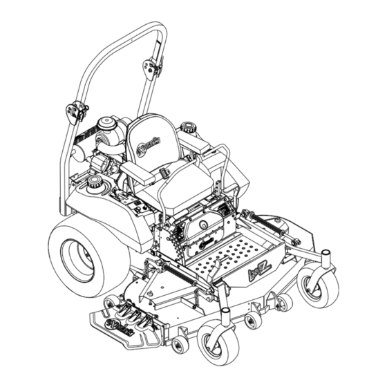
Page 17: Torque Requirements
Product Overview Overall Height: Product Overview Roll Bar - Up Roll Bar - Down 71.9 in. (182.6 cm) 53.8 inches (136.7 cm) Tread Width: (Center to Center of Tires, Widthwise) Drive Wheels 41.9 inches (106.4 cm) Caster Wheels 37.3 inches (94.7 cm) Wheel Base: (Center of Caster Tire to Center of Drive Tire) 53.7 inches (136.4 cm) -
Page 18: Operation
Operation Operation Push the lever forward and down to disengage the brake. Note: Determine the left and right sides of the The unit must be tied down and brake engaged when machine from the normal operating position. transporting. Controls Ignition Switch Located on right fuel tank. -
Page 19: Pre-Start
Operation Drive Wheel Release Valves 1. Remove the hairpin cotter pins and remove the two roll bar pins (Figure 5). Located on the top right front corner of hydrostatic 2. Raise the roll bar to the upright position and pumps. install the two pins and secure them with the Drive wheel release valves are used to release the hairpin cotter pins (Figure 5). -
Page 20: Stopping The Engine
Operation 4. Place the throttle midway between the “SLOW” 2. Pull the PTO switch outward to the “ROTATE” and “FAST” positions. position. 5. On a cold engine, push the choke lever forward 3. Place the throttle in the “FAST” position to begin into the “ON”... -
Page 21: Adjusting The Cutting Height
Operation When levers are centered in the T-slot the drive system is in the neutral position. With levers moved out in the T-slot the drive system is in the neutral lock position (Figure 6). Figure 6 Figure 7 1. Handles Out (Neutral 5. -
Page 22: Adjusting The Anti-Scalp Rollers
Operation deck lift assist lever located at the front right 6. Place the rollers in one of the positions shown corner of the floor pan. (Figure 9). Rollers will maintain 3/4 inch (19 mm) clearance to the ground to minimize gouging and Note: When changing the cutting height roller wear or damage. -
Page 23: Transporting
Operation WARNING Loading a unit on a trailer or truck increases the possibility of backward tip-over. Backward tip-over could cause serious injury or death. • Use extreme caution when operating a unit on a ramp. • Use only a single, full width ramp; Do Not use individual ramps for each side of the unit. - Page 24 Operation Important: Do Not attempt to turn the unit while on the ramp, you may lose control and drive off the side. Avoid sudden acceleration when driving up a ramp and sudden deceleration when backing down a ramp. Both maneuvers can cause the unit to tip backward.
-
Page 25: Maintenance
Maintenance Maintenance Note: Determine the left and right sides of the machine from the normal operating position. WARNING WARNING While maintenance or adjustments are being The engine can become very hot. Touching made, someone could start the engine. a hot engine can cause severe burns. Accidental starting of the engine could Allow the engine to cool completely before seriously injure you or other bystanders. -
Page 26: Periodic Maintenance
Maintenance Maintenance Service Maintenance Procedure Interval • Grease the brake brackets. Every 200 hours • Check the wheel hub slotted nut torque specifications. Every 500 hours • Check the wheel lug nuts. • Check the battery charge. Monthly • Grease front caster pivots. •... -
Page 27: Check Mower Blades
Always install the original Exmark blades, blade bushings, and blade bolts as shown. Figure 11 Check Safety Interlock 1. -
Page 28: Check Rollover Protections Systems (Roll Bar) Pins
Note: If machine does not pass any of these tests, 4. Remove paper element. Check the condition do not operate. Contact your authorized EXMARK of the paper element. Replace if dirty, bent or SERVICE DEALER. damaged. -
Page 29: Change Engine Oil
Maintenance 6. Do Not wash or use pressurized air to clean the level of oil when it is at 225°F (107°C). The paper element or inner element. “COLD” level shows the level of the oil when it is at 75°F (24°C). Fill to the appropriate level 7. -
Page 30: Lubricate Caster Wheel Hubs
Maintenance Lubrication Chart Fitting Initial Number of Service Locations Pumps Places Interval 1. Front *Yearly Caster Wheel Hubs 2. Front *Yearly Caster Pivots 3. Height 40 Hours Adjustment Shaft Bearings 4. Deck Yearly Drive Belt Idler Arm Number 6 (Mule Drive Belt Idler Arm) Located 5. -
Page 31: Lubricate Brake Handle Pivot
7. Insert one bearing, one new seal into the wheel. Service Interval: Every 160 hours Note: Seals (Exmark P/N 103-0063) must be 1. Stop engine, wait for all moving parts to stop, and remove key. Engage parking brake. -
Page 32: Change Hydraulic System Filter
Two threads (0.1 inch) or less should be showing. Note: Use only Exmark Part No. 109-4180 for summer use above 32°F (0°C) or Part No. 1-523541 3. If more than two threads (0.1 inch) are showing for winter use below 32°F (0°C). -
Page 33: Mobil Hts Grease (Or Food-Grade Anti-Seize)
Maintenance Adjustments • Caster wheel spacer nuts. • Fuel tank bulkhead fitting nuts. Note: Disengage PTO, shut off engine, wait for all moving parts to stop, engage parking brake, and Adhesives such as “Loctite RC/609 or RC/680” or remove key before servicing, cleaning, or making any “Fel-Pro Pro-Lock Retaining I or Retaining II”... -
Page 34: Pump Drive Belt Tension
Maintenance all the chains is approximately equal. Make sure center of the bolt head is at or below the center all chain attachment bolts are tight. Reposition of the bottom alignment hole. anti-scalp rollers and tighten securely. 3. When adjustment is necessary, loosen the idler pulley on the right-hand side so it can move up and down in the slot. -
Page 35: Deck Belt Tension
Maintenance Brake Link Adjustment Check to make sure brake is adjusted properly. 1. Disengage brake lever (lever down). 2. Measure the length of the spring. Measurement should be 2 3/4 inches (7.0 cm) between washers. (Figure 18). 3. If adjustment is necessary, tighten the nut directly below the yoke and loosen the bottom nut (bottom one of the two tightened together) below the spring. -
Page 36: Electric Clutch Adjustment
Maintenance between the spring retainer bracket and the adjacent nyloc nut. Tighten the jam nut above the trunnion roller. 4. If adjustment is necessary, loosen the nut directly below the yoke. Turn the bottom nut (below washer) until the correct measurement is obtained (see Figure 18) turn nut clockwise to lengthen the gap (screws rod into yoke) and turn counterclockwise to shorten the gap (screws... -
Page 37: Motion Control Damper Adjustment
Maintenance 1. This adjustment must be made with the drive appropriate direction until the wheels slightly wheels turning. First raise the frame and block up creep in reverse (Figure 20). Move the motion so that drive wheels can rotate freely. control lever to the reverse position and while applying slight pressure to the lever allow the 2. -
Page 38: Adjust Seat Switch
Maintenance Caster Pivot Bearings Pre-Load Adjustment Remove dust cap from caster and tighten nyloc nut until washers are flat and back off 1/4 of a turn to properly set the pre-load on the bearings. If disassembled, make sure the spring disc washers are reinstalled as shown in Figure 23. -
Page 39: Cleaning
Maintenance Cleaning Clean Grass Build-Up Under Deck Clean Engine Cooling Service Interval: Before each use or daily System 1. Stop engine, wait for all moving parts to stop, and remove key. Engage parking brake. Service Interval: Before each use or daily 2. - Page 40 Maintenance Federal law states that batteries should not be placed in the garbage. Management and disposal practices must be within relevant federal, state, or local laws. If a battery is being replaced or if the unit containing the battery is no longer operating and is being scrapped, take the battery to a local certified recycling center.
-
Page 41: Troubleshooting
Troubleshooting Troubleshooting Important: It is essential that all operator safety mechanisms be connected and in proper operating condition prior to mower use. When a problem occurs, do not overlook the simple causes. For example: starting problems could be caused by an empty fuel tank. The following table lists some of the common causes of trouble. - Page 42 Troubleshooting Problem Possible Cause Corrective Action Engine overheats 1. Engine load is excessive 1. Reduce the ground speed. 2. Oil level in the crankcase is low. 2. Add oil to the crankcase. 3. Cooling fins and air passages for the 3.
-
Page 43: Schematics
Schematics Schematics Electrical Diagram GREEN GREEN STRIPE GREEN/WHITE WHITE BLACK BLACK BLACK BLACK BLACK BLACK GREEN GREEN BLACK STRIPE ORANGE/BLACK GREY STRIPE GREEN/WHITE YELLOW BLUE BROWN GREEN GREEN STRIPE PINK/BLACK BLUE BROWN BLUE BLUE BLUE GREEN BLACK GREEN GREY GREEN BLUE G006132... - Page 44 Schematics Hydraulic Diagram...
- Page 45 No Claim of breach of warranty shall be cause for cancellation included with the product. or rescission of the contract of sale of any Exmark mower. All warranty work must be performed by an authorized Some states do not allow exclusions of incidental or...
-
Page 46: Service Record
Service Record Date: Description of Work Done: Service Done By:... - Page 48 © 2007 Exmark Mfg. Co., Inc. Part No. 4500-246 Rev. A Industrial Park Box 808 (402) 223-6300 Beatrice, NE 68310 Fax (402) 223–5489 All Rights Reserved Printed in the USA.