
Related Manuals for Emerson NXL UPS Systems


Summary of Contents for Emerson NXL UPS Systems
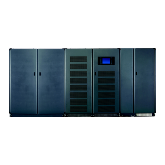
- Page 1 Liebert Maintenance Bypass Cabinet ® ™ Installation Manual – 250-400kVA, 60Hz AC Power For Business-Critical Continuity™...
-
Page 2: Product Warranty Registration
ONTACTING IEBERT FOR To contact Emerson Network Power Liebert Services for information or repair service in the United States, call 1-800-LIEBERT (1-800-543-2378). Liebert Services offers a complete range of start-up services, repair services, preventive maintenance plans and service contracts. For repair or maintenance service outside the 48 contiguous United States, contact Liebert Services, if available in your area. -
Page 3: Table Of Contents
MPORTANT AFETY NSTRUCTIONS INGLE ODULE ECHANICAL Introduction ..............2 Preliminary Checks . - Page 4 Figure 1 Cabinet arrangement—Liebert NXL UPS, battery cabinets, maintenance bypass cabinet..4 Figure 2 Two-Breaker Maintenance Bypass Cabinet, one-input, attached ......7 Figure 3 Two-Breaker Maintenance Bypass Cabinet, two-input, attached .
-
Page 5: Important Safety Instructions
MPORTANT AFETY NSTRUCTIONS SAVE THESE INSTRUCTIONS This manual contains important instructions that should be followed during installation of your Liebert NXL Maintenance Bypass Cabinet. ™ WARNING Exercise extreme care when handling cabinets to avoid equipment damage or injury to personnel. The Liebert NXL Maintenance Bypass Cabinet weight ranges from 700 to 900 lb (317 to 409kg). -
Page 6: Single -Module Mechanical Installation
INGLE ODULE Introduction This section describes the requirements that must be taken into account when planning the position- ing and cabling of the Liebert NXL Maintenance Bypass Cabinet. This chapter is a guide to general procedures and practices that should be observed by the installing engineer. -
Page 7: Storage
1.3.2 Storage Should the equipment not be installed immediately, it must be stored in a room for protection against excessive humidity and or heat sources (see Table 6). Positioning The cabinet is structurally designed to handle lifting from the base. Access to the power terminals, auxiliary terminals blocks and power switches is from the front. -
Page 8: Power Cables
Power Cables The Maintenance Bypass Cabinet requires both power and control cabling once it has been mechani- cally installed. All control cables must be separate from the power cables. Run control cables in metal conduits or metal ducts that are electrically bonded to the cabinets they are connected to. The cable design must comply with the voltages and currents provided in Tables 7 and 8, follow local wiring practices and take into consideration the environmental conditions (temperature and physical support media). -
Page 9: Power Cable Connection Procedure
The operations described in this section must be performed by authorized electricians or qualified technical personnel. If you have any difficulties, do not hesitate to contact Emerson Network Power Liebert Services. See the back page of this manual for contact information. - Page 10 Once the equipment has been finally positioned and secured, connect the power cables as described in the following procedure. Refer to the appropriate cable connection drawing in 2.0 - Installation Drawings. 1. Verify that the bypass equipment is isolated from its external power source and all the power isolators are open.
-
Page 11: Installation Drawings
NSTALLATION RAWINGS Figure 2 Two-Breaker Maintenance Bypass Cabinet, one-input, attached Main Input Switchgear UPS Module Battery System Two Breaker Maintenance Bypass Cabinet DC Bus MIB - Maintenance Isolation Breaker MBB - Maintenance Bypass Breaker FBO – Furnished By Others N – Neutral EG –... -
Page 12: Figure 3 Two-Breaker Maintenance Bypass Cabinet, Two-Input, Attached
Figure 3 Two-Breaker Maintenance Bypass Cabinet, two-input, attached Main Input Switchgear UPS Module Battery System Figure 4 Two-Breaker Maintenance Bypass Cabinet, three-input, attached or detached Main Input Switchgear UPS Module Battery System Two Breaker Maintenance Bypass Cabinet DC Bus MIB - Maintenance Isolation Breaker BIB - Bypass Input Breaker MBB - Maintenance Bypass Breaker FBO –... -
Page 13: Figure 5 Liebert Nxl Maintenance Bypass Cabinet-250 And 300Kva Main Component Location
Figure 5 Liebert NXL Maintenance Bypass Cabinet—250 and 300kVA main component location OPTIONAL SOLENOID INTERLOCK MAINTENANCE ISOLATION BREAKER (MIB) INPUT PHASE C OUTPUT INPUT PHASE A PHASE A INPUT PHASE B GROUND NEUTRAL BUSBAR DETAIL B MAINTENANCE BYPASS BREAKER (MBB) CONTROL WIRING TERMINAL BLOCK (TB1) -
Page 14: Figure 6 Liebert Nxl Maintenance Bypass Cabinet-400Kva Main Component Location
Figure 6 Liebert NXL Maintenance Bypass Cabinet—400kVA main component location GROUND OPTIONAL SOLENOID INTERLOCK MAINTENANCE ISOLATION BREAKER (MIB) FRONT INPUT OUTPUT PHASE C PHASE C OUTPUT INPUT PHASE A PHASE A INPUT OUTPUT PHASE B PHASE B BREAKER REMOVED FOR CLARITY NEUTRAL BUSBAR DE TAIL B MAINTENANCE... -
Page 15: Figure 7 Liebert Nxl Maintenance Bypass Cabinet-250 And 300Kva Outline Drawing
Figure 7 Liebert NXL Maintenance Bypass Cabinet—250 and 300kVA outline drawing 24.0 ( 610) 24.8 ( 630) KNOCK-OUT FOR CONTROL WIRING O 1" 3 PLCS TOP VIEW (DOOR OPEN) 76.8 ( 1951) 38.5 ( 979) 12.2 (309) 24.2 (615) NOTES: 1. -
Page 16: Figure 8 Liebert Nxl Maintenance Bypass Cabinet-400Kva Outline Drawing
Figure 8 Liebert NXL Maintenance Bypass Cabinet—400kVA outline drawing 24.0 ( 610) 30.8 (782) Knock-out for control wiring O 1.0" (25.4mm) 3 Places TOP VIEW (DOOR OPEN) 76.8 (1950) 38.5 (979) 12.2 (309) 24.2 (615) See Note 10 FRONT NOTES: 1. -
Page 17: Figure 9 Liebert Nxl Maintenance Bypass Cabinet-250 And 300Kva Terminal Details
Figure 9 Liebert NXL Maintenance Bypass Cabinet—250 and 300kVA terminal details ( 65 ) ( 40 ) ( 51 ) ( 45 ) TOP VIEW BREAKER REMOVED FOR CLARIT Y FRONT VIEW ( 65 ) ( 51 ) ( 123 ) BUS BAR DETAIL A 8 PLACES BUS TERMINATION DETAIL... -
Page 18: Figure 10 Liebert Nxl Maintenance Bypass Cabinet-400Kva Terminal Details
Figure 10 Liebert NXL Maintenance Bypass Cabinet—400Kva terminal details ( 65 ) 1.59 ( 40 ) 2.00 ( 51 ) TOP VIEW BREAKERS REMOVED FOR CLARITY FRONT VIEW 2.57 2.57 ( 65) 4.59 (117) 2.00 ( 51) 4.84 (123 ) 1.78 ( 45 ) BUSBAR DETAIL A... -
Page 19: Figure 11 Cable Routing
Figure 11 Cable routing TOP ENTRY NOTES: 1. Cables from lower busbars must be routed and tied to the aligning holes on the the cable landing bar directly above (see figure below). Installation method is to prevent cables from lower busbars from contacting the upper busbars. -
Page 20: Figure 12 Liebert Nxl Maintenance Bypass Cabinet, One-Input System, Point-To-Point Wiring
Figure 12 Liebert NXL Maintenance Bypass Cabinet, one-input system, point-to-point wiring to UPS FRONT Installation Drawings BYPASS NEUTRAL OUTPUT NEUTRAL... -
Page 21: Liebert-Supplied Interconnect Wiring For One-Input Liebert Nxl Maintenance
Table 1 Liebert-supplied interconnect wiring for one-input Liebert NXL Maintenance Bypass Cabinet Utility AC - Phase A Utility AC - Phase B Utility AC - Phase C Utility Neutral Utility Ground MBC Bypass AC - Phase A MBC Bypass AC - Phase B MBC Bypass AC - Phase C UPS Bypass AC - Phase A UPS Bypass AC - Phase B... -
Page 22: Figure 13 Liebert Nxl Maintenance Bypass Cabinet, Two-Input System, Point-To-Point Wiring
Figure 13 Liebert NXL Maintenance Bypass Cabinet, two-input system, point-to-point wiring to UPS FRONT Installation Drawings BYPASS NEUTRAL OUTPUT NEUTRAL... -
Page 23: Liebert-Supplied Interconnect Wiring For Two-Input Liebert Nxl Maintenance
Table 2 Liebert-supplied interconnect wiring for two-input Liebert NXL Maintenance Bypass Cabinet Utility AC - Phase A Utility AC - Phase B Utility AC - Phase C Utility Neutral Utility Ground MBC Bypass AC - Phase A MBC Bypass AC - Phase B MBC Bypass AC - Phase C Utility Bypass AC - Phase A Utility Bypass AC - Phase B... -
Page 24: Figure 14 Liebert Nxl Maintenance Bypass Cabinet, Three-Input System, Point-To-Point Wiring
Figure 14 Liebert NXL Maintenance Bypass Cabinet, three-input system, point-to-point wiring to UPS FRONT Installation Drawings BYPASS NEUTRAL OUTPUT NEUTRAL... -
Page 25: Liebert-Supplied Interconnect Wiring For Three-Input Liebert Nxl Maintenance
Table 3 Liebert-supplied interconnect wiring for three-input Liebert NXL Maintenance Bypass Cabinet Utility AC - Phase A Utility AC - Phase B Utility AC - Phase C Utility Neutral Utility Ground Utility AC - Phase A Utility AC - Phase B Utility AC - Phase C Utility AC - Phase A Utility AC - Phase B... -
Page 26: Figure 15 Liebert Nxl Maintenance Bypass Cabinet Control Wire Diagram Without Interlock
Figure 15 Liebert NXL Maintenance Bypass Cabinet Control wire diagram without interlock LOW VOLTAGE TERMINAL STRIP - TB1 - TB1-13 TB0813 TB1-12 TB1-11 TB1-10 TB0811 TB1-9 TB1-8 TB1-7 TB0823 TB1-6 TB1-5 TB1-4 TB0821 TB1-3 TB1-2 EPO PB SW TB1-1 WIRE DIAGRAM WITHOUT INTERLOCK Connections at UPS External Interface Board (EIB) 02-806708... -
Page 27: Figure 16 Liebert Nxl Maintenance Bypass Cabinet Control Wire Diagram With Interlock
Figure 16 Liebert NXL Maintenance Bypass Cabinet control wire diagram with interlock LOW VOLTAGE TERMINAL STRIP - TB1 - TB1-16 TB0820 TB1-15 TB1-14 TB1-13 TB0813 TB1-12 TB1-11 TB1-10 TB0811 TB1-9 TB1-8 TB1-7 TB0824 TB1-6 TB1-5 TB1-4 TB0821 TB1-3 TB1-2 EPO PB SW TB1-1 WIRE DIAGRAM WITH INTERLOCK Connections at UPS External... -
Page 28: Figure 17 Liebert Nxl Maintenance Bypass Cabinet Control Wire Routing
Figure 17 Liebert NXL Maintenance Bypass Cabinet control wire routing CONDUIT KNOCK-OUTS FOR CONTROL WIRING INTERNAL ROUTING FOR CONTROL WIRING INTERNAL ROUNTING FOR CONTROL WIRING CONDUIT KNOCK-OUTS FOR CONTROL WIRING SECTION A-A Installation Drawings FRONT VIEW... -
Page 29: Figure 18 Ground Strap Location For Connected Cabinets
Figure 18 Ground strap location for connected cabinets FRONT SIDE OF UNITS Typical Ground Strap Installation (Use for all connected units except Battery Cabinet) DETAIL A Installation Drawings Reference of corner post of connected cabinets Cabinet-to-Cabinet Bolting Instructions... -
Page 30: Specifications
PECIFICATIONS Table 6 Liebert NXL Maintenance Bypass Cabinet specifications Model Size Input Parameters Input Voltage to Bypass, VAC Permissible Input Voltage Range, VAC Input Frequency, Hz Permissible Input Frequency Range, Hz Neutral Current Output Parameters Output Power, kW Output Voltage, VAC Output Frequency, Hz Physical Parameters &... -
Page 31: Table 7 Liebert Nxl Maintenance Bypass Cabinet Current Ratings-System Input
Table 7 Liebert NXL Maintenance Bypass Cabinet current ratings—System Input UPS Rating Voltage (VAC) Input Bypass Table 8 Liebert NXL Maintenance Bypass Cabinet current ratings—System Output UPS Rating Voltage, VAC Input Bypass Table 9 Recommended conduit and cable sizes—Maintenance Bypass Input UPS Rating System Input Voltage (VAC) Maint... -
Page 32: Table 11 Recommended Conduit And Cable Sizes-Module Bypass Input
Table 11 Recommended conduit and cable sizes—Module Bypass Input Rating System Input Voltage (VAC) Maint kVA kW Rectifier Bypass Output 250 225 300 270 400 360 500 450 Table 12 Recommended conduit and cable sizes—Module Output System Rating Input Voltage (VAC) Maint kVA kW Rectifier Bypass Output... -
Page 33: Table 15 Recommended Lug Sizes
Notes See the Liebert NXL UPS installation manual, SL-25420, for UPS rectifier, UPS bypass and UPS out- put sizes. The manual is available at the Liebert Web site: These are guidelines only and are superseded by local regulations and codes of practice where appli- cable. - Page 34 Specifications...
- Page 36 Embedded Computing Connectivity Embedded Power DC Power Monitoring Business-Critical Continuity, Emerson Network Power and the Emerson Network Power logo are trademarks and service marks of Emerson Electric Co. ©2008 Emerson Electric Co. Technical Support / Service monitoring@emersonnetworkpower.com Outside the US: 614-841-6755 upstech@emersonnetworkpower.com...