Table of Contents
Advertisement
Advertisement
Table of Contents

Related Manuals for Draytek VIGOR 2700GE/E


Summary of Contents for Draytek VIGOR 2700GE/E
- Page 2 Vigor 2700Ge/e A D S L 2/2+ F irew a l l R ou t er U ser’s Gu id e Version: 1.0 D a t e: 2 005 /11/14 Copyright 2005 All rights reserved. This publication contains information that is protected by copyright. No part may be reproduced, transmitted, transcribed, stored in a retrieval system, or translated into any language without written permission from the copyright holders.
- Page 3 Vigor2700Ge/e User’s Guide...
-
Page 4: Table Of Contents
Preface........................1 1.1 LED Indicators and Connectors ...................1 1.1.1 LED Explanation ......................1 1.1.2 Connector Explanation ....................2 1.2 Hardware Installation......................2 Configuring Basic Settings................5 2.1 Changing Password ......................5 2.2 Quick Start Wizard.......................7 2.2.1 Adjusting Protocol/Encapsulation ..................7 2.2.2 PPPoE/PPPoA......................8 2.2.3 Bridged IP........................9 2.2.4 Routed IP........................11 2.3 Online Status........................12 2.4 Saving Configuration ......................14 Advanced Web Configuration..................15... - Page 5 3.4.7 URL Content Filter ......................48 3.4.8 Web Content Filter ......................50 3.5 Applications........................50 3.5.1 Dynamic DNS ......................50 3.5.2 Schedule........................52 3.5.3 UPnP ..........................54 3.6 Wireless LAN ........................55 3.8.1 Basic Concept......................56 3.6.2 General Settings ......................57 3.6.3 Security........................58 3.6.4 Access Control......................59 3.7 System Maintenance......................60 3.7.1 System Status......................60 3.7.2 Administrator Password ....................61 3.7.3 Configuration Backup....................62...
-
Page 6: Preface
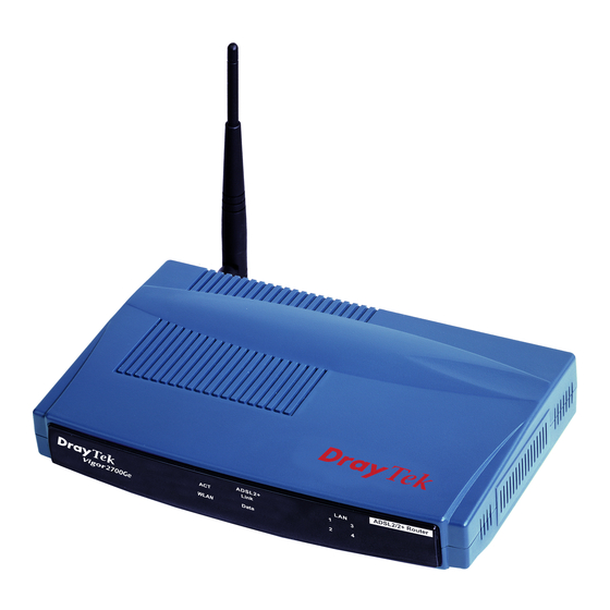
Targeting requirement for residential, SOHO (Small Office and Home Office) and business users, the Vigor2700Ge/e is an ADSL2/2+ enabled integrated access device. With downstream speed up to 12Mbps (ADSL2) or 24Mbps (ADSL2+), the Vigor2700Ge/e provides exceptional bandwidth for Internet access. To secure your network, the Vigor2700Ge/e provides an advanced firewall with advanced features, such as Stateful Packet Inspection (SPI) to offer network reliability by detecting and prohibiting malicious penetrating packets or DoS attacks, user-configurable web filtering for... -
Page 7: Connector Explanation
Factory Reset ADSL2+ for Annex A Factory Reset ADSL2+ for Annex B Factory Reset ADSL2+ for Annex A Factory Reset ADSL2+ for Annex B Interface Description ADSL 2+ Connecter for accessing the Internet through ADSL 2+. LAN 4 – 1 Connecter for local networked devices. - Page 8 Vigor2700Ge/e User’s Guide...
- Page 9 Vigor2700Ge/e User’s Guide...
-
Page 10: Configuring Basic Settings
For use the router properly, it is necessary for you to change the password of web configuration for security and adjust primary basic settings. This chapter explains how to setup a password for an administrator and how to adjust basic settings for accessing Internet successfully. - Page 11 Go to System Maintenance page and choose Administrator Password. Enter the login password (the default is blank) on the field of Old Password. Type a new one in the field of New Password and retype it on the field of Retype New Password. Then click OK to continue.
-
Page 12: Quick Start Wizard
If your router can be under an environment with high speed NAT, the configuration provide here can help you to deploy and use the router quickly. The first screen of Quick Start Wizard is entering login password. After typing the password, please click Next. In the Quick Start Wizard, you can configure the router to access the Internet with different protocol/modes such as PPPoE, PPPoA, Bridged IP, or Routed IP. -
Page 13: Pppoe/Pppoa
Stands for Virtual Channel Identifier. It is a 16-bit field inside ATM cell’s header that indicates the cell’s next destination as it travels through the network. A virtual channel is a logical connection between two end devices on the network. Protocol/Encapsulation Select an IP mode for this WAN interface. -
Page 14: Bridged Ip
User Name Assign a specific valid user name provided by the ISP. Password Assign a valid password provided by the ISP. Confirm Password Retype the password. Always On Check this box to allow the router connecting to Internet forever. Idle Timeout Type in the value (unit is second) as the idle timeout of the connection. - Page 15 After finishing the settings in this page, click Next to see the following page. Click Finish. The online status of this protocol will be shown as below. Vigor2700Ge/e User’s Guide...
-
Page 16: Routed Ip
Click 1483 Routed IP as the protocol. Type in all the information that your ISP provides for this protocol. After finishing the settings in this page, click Next to see the following page. Click Finish. The online status of this protocol will be shown as below. Vigor2700Ge/e User’s Guide... -
Page 17: Online Status
The online status shows the system status, WAN status, ADSL Information and other status related to this router within one page. If you select PPPoE or PPPoA as the protocol, you will find out a button of Dial PPPoE or Dial PPPoE in the Online Status web page. Online status for PPPoA/PPPoE Vigor2700Ge/e User’s Guide... - Page 18 Online status for Bridge Online status for Routed IP Primary DNS Displays the assigned IP address of the primary DNS. Secondary DNS Displays the assigned IP address of the secondary DNS. IP Address (in LAN) Displays the IP address of the LAN interface. TX Packets Displays the total transmitted packets at the LAN interface.
-
Page 19: Saving Configuration
Each time you click OK on the web page for saving the configuration, you can find messages showing the system interaction with you. Ready indicates the system is ready for you to input settings. Settings Saved means your settings are saved once you click Finish or OK button. Vigor2700Ge/e User’s Guide... -
Page 20: Advanced Web Configuration
After finished basic configuration of the router, you can access Internet with ease. For the people who want to adjust more settings for suiting his/her request, please refer to this chapter for getting detailed information about the advanced configuration of this router. As for other examples of application, please refer to Chapter 4. -
Page 21: Pppoe/Pppoa
PPPoA, included in RFC1483, can be operated in either Logical Link Control-Subnetwork Access Protocol or VC-Mux mode. As a CPE device, Vigor router encapsulates the PPP session based for transport across the ADSL loop and your ISP’s Digital Subscriber Line Access Pultiplexer (SDLAM). - Page 22 For Wired LAN – If you check this box, PCs on the same network can use another set of PPPoE session (different with the Host PC) to access into Internet. For Wireless LAN – If you check this box, PCs on the same network through wireless connection can use another set of PPPoE session (different with the Host PC) to access into Internet.
-
Page 23: Mpoa
If you do not check Join NAT IP Pool, you can still use these public IP addresses for other purpose, such as DMZ host, Open Ports. Default MAC Address Type in MAC address for the router. You can use Default MAC Address or specify another MAC address for your necessity. - Page 24 To choose MPoA as the accessing protocol of the internet, please select MPoA from the Internet Access menu. The following web page will be shown. MPoA (RFC1483/2684) Click Enable for activating this function. If you click Disable, this function will be closed and all the settings that you adjusted in this page will be invalid.
-
Page 25: Multi-Pvcs
Specify an IP address – Click this radio button to specify some data. IP Address – Type in the private IP address. Subnet Mask – Type in the subnet mask. Gateway IP Address – Type in gateway IP address. Default MAC Address Type in MAC address for the router. You can use Default MAC Address or specify another MAC address for your necessity. -
Page 26: Lan
Type in the value provided by your ISP. Type in the value provided by your ISP. QoS Type Select a proper QoS type for the channel. Protocol Select a proper protocol for this channel. Encapsulation Choose a proper type for this channel. The types will be different according to the protocol setting that you choose. - Page 27 In some special case, you may have a public IP subnet from your ISP such as 220.135.240.0/24. This means that you can set up a public subnet or call second subnet that each host is equipped with a public IP address. As a part of the public subnet, the Vigor router will serve for IP routing to help hosts in the public subnet to communicate with other public hosts or servers outside.
-
Page 28: General Setup
You can group local hosts by physical ports and create up to 4 virtual LANs. To manage the communication between different groups, please set up rules in Virtual LAN (VLAN) function and the rate of each. This page provides you the general settings for LAN. Click LAN to open the LAN settings page and choose General Setup. - Page 29 DHCP Server You can configure the router to serve as a DHCP server for the 2nd subnet. Start IP Address: Enter a value of the IP address pool for the DHCP server to start with when issuing IP addresses. If the 2nd IP address of your router is 220.135.240.1, the starting IP address must be 220.135.240.2 or greater, but smaller than 220.135.240.254.
-
Page 30: Static Route
Enable Server - Let the router assign IP address to every host in the LAN. Disable Server – Let you manually assign IP address to every host in the LAN. Relay Agent – (1 subnet/2 subnet) Specify which subnet that DHCP server is located the relay agent should redirect the DHCP request to. - Page 31 Index The number (1 to 10) under Index allows you to open next page to setup static route. Destination Address Displays the destination address of the static route. Status Displays the status of the static route. Viewing Routing Table Displays the routing table for your reference. Here is an example of setting Static Route in Main Router so that user A and B locating in different subnet can talk to each other via the router.
- Page 32 Go to LAN page and click General Setup, select 1st Subnet as the RIP Protocol Control. Then click the OK button. Note: There are two reasons that we have to apply RIP Protocol Control on 1st Subnet. The first is that the LAN interface can exchange RIP packets with the neighboring routers via the 1st subnet (192.168.1.0/24).
-
Page 33: Vlan
Go to Diagnostics and choose Routing Table to verify current routing table. Go to LAN page and click Static Route to open the web page. Select the index number of the one that you want to delete. Select Empty/Clear from the drop-down menu, and then click the OK button to delete the route. - Page 34 To add or remove a VLAN, please refer to the following example. If, VLAN 0 is consisted of hosts linked to P1 and P2 and VLAN 1 is consisted of hosts linked to P3 and P4. After checking the box to enable VLAN function, you will check the table according to the needs as shown below.
-
Page 35: Nat
Usually, the router serves as an NAT (Network Address Translation) router. NAT is a mechanism that one or more private IP addresses can be mapped into a single public one. Public IP address is usually assigned by your ISP, for which you may get charged. Private IP addresses are recognized only among internal hosts. - Page 36 The port redirection can only apply to incoming traffic. The server users inside the LAN can not access public IP address of the server. The correct route is to access the server using the local private IP address of the server, or you should set up an alias in a Windows hosts file. Please only redirect the ports you know you have to forward rather than forward all ports.
-
Page 37: Dmz Host
Private Port Specify the private port number of the service offered by the internal host. Active Check this box to activate the port-mapping entry you have defined. Note that the router has its own built-in services (servers) such as Telnet, HTTP and FTP etc. Since the common port numbers of these services (servers) are all the same, you may need to reset the router’s in order to avoid confliction. - Page 38 The inherent security properties of NAT are somewhat bypassed if you set up DMZ host. We suggest you to add additional filter rules or a secondary firewall. Click DMZ Host to open the following page: If you previously have set up WAN Alias in Internet Access>>PPPoE/PPPoA or Internet Access>>MPoA, you will find them in Aux.
-
Page 39: Open Ports
When you have selected one private IP from the above dialog, the IP address will be shown on the following screen. Click OK to save the setting. Open Ports allows you to open a range of ports for the traffic of special applications. Common application of Open Ports includes P2P application (e.g., BT, KaZaA, Gnutella, WinMX, eMule and others), Internet Camera etc. - Page 40 To add or edit port settings, click one index number on the page. The index entry setup page will pop up. In each index entry, you can specify 10 port ranges for diverse services. However, if you previously have set up WAN Alias in Internet Access>>PPPoE/PPPoA or Internet Access>>MPoA, you will find that WAN IP appeared for your selection.
-
Page 41: Well-Known Ports List
This page provides you a view of well-known ports. While the broadband users demand more bandwidth for multimedia, interactive applications, or distance learning, security has been always the most concerned. The firewall of the Vigor router helps to protect your local network against attack from unauthorized outsiders. It also restricts users in the local network from accessing the Internet. - Page 42 The users on the LAN are provided with secured protection by the following firewall facilities: User-configurable IP filter (Call Filter/ Data Filter). Stateful Packet Inspection (SPI): tracks packets and denies unsolicited incoming data Selectable Denial of Service (DoS) /Distributed DoS (DDoS) attacks protection URL Content Filter Depending on whether there is an existing Internet connection, or in other words “the WAN link status is up or down”, the IP filter architecture categorizes traffic into two: Call Filter and...
- Page 43 Stateful inspection is a firewall architecture that works at the network layer. Unlike legacy static packet filtering, which examines a packet based on the information in its header, stateful inspection builds up a state machine to track each connection traversing all interfaces of the firewall and makes sure they are valid.
-
Page 44: General Setup
To provide an appropriate cyberspace to users, Vigor router equips with URL Content Filter not only to limit illegal traffic from/to the inappropriate web sites but also prohibit other web feature where malicious code may conceal. Once a user type in or click on an URL with objectionable keywords, URL keyword blocking facility will decline the HTTP request to that web page thus can limit user’s access to the website. - Page 45 Call Filter Check Enable to activate the Call Filter function. Assign a start filter set for the Call Filter. Data Filter Check Enable to activate the Data Filter function. Assign a start filter set for the Data Filter. Log Flag For troubleshooting needs you can specify the filter log here.
-
Page 46: Filter Setup
Click Firewall and click Filter Setup to open the setup page. To edit or add a filter, click on the set number to edit the individual set. The following page will be shown. Each filter set contains up to 7 rules. Click on the rule number button to edit each rule. - Page 47 Comments Enter filter set comments/description. Maximum length is 14- character long. Check this box to enable the filter rule. Check to enable the Filter Rule Pass or Block Specifies the action to be taken when packets match the rule. Block Immediately - Packets matching the rule will be dropped immediately.
- Page 48 the Start Port and the End Port). (!=)If the End Port is empty, the port number is not equal to the value of the Start Port. Otherwise, this port number is not between the Start Port and the End Port (including the Start Port and End Port).
-
Page 49: Im Blocking
As stated before, all the traffic will be separated and arbitrated using on of two IP filters: call filter or data filter. You may preset 12 call filters and data filters in Filter Setup and even link them in a serial manner. Each filter set is composed by 7 filter rules, which can be further defined. -
Page 50: P2P Blocking
P2P is the short name of peer to peer. Click Firewall and click P2P Blocking to open the setup page. You will see a list of common P2P applications. Check Enable P2P Blocking and select the one(s) to block. To block selected P2P applications during specific periods, enter the number of the scheduler predefined in Applications>>Call Schedule. -
Page 51: Dos Defense
As a sub-functionality of IP Filter/Firewall, there are 15 types of detect/ defense function in the DoS Defense setup. The DoS Defense functionality is disabled for default. Click Firewall and click DoS Defense to open the setup page. Enable Dos Defense Check the box to activate the DoS Defense Functionality. - Page 52 port-scanning Threshold rate, the Vigor router will send out a warning. By default, the Vigor router sets the threshold as 150 packets per second. Block IP options Check the box to activate the Block IP options function. The Vigor router will ignore any IP packets with IP option field in the datagram header.
-
Page 53: Url Content Filter
SYN packets with the identical source and destination addresses, as well as the port number to victims. Check the box to activate the Block Unknown Protocol function. Block Unknown Protocol Individual IP packet has a protocol field in the datagram header to indicate the protocol type running over the upper layer. - Page 54 Enable URL Access Check the box to activate URL Access Control. Control Black List (block those Click this button to restrict accessing into the corresponding webpage with the keywords listed on the box below. matching keyword) White List (pass those Click this button to allow accessing into the corresponding webpage with the keywords listed on the box below.
-
Page 55: Web Content Filter
Enable Restrict Web Check the box to activate the function. Java - Check the checkbox to activate the Block Java object Feature function. The Vigor router will discard the Java objects from the Internet. ActiveX - Check the box to activate the Block ActiveX object function. - Page 56 Assume you have a registered domain name from the DDNS provider, say hostname.dyndns.org, and an account with username: test and password: test. In the DDNS setup menu, check Enable Dynamic DNS Setup. Select Index number 1 to add an account for the router. Check Enable Dynamic DNS Account, and choose correct Service Provider: dyndns.org, type the registered hostname: hostname and domain name suffix: dyndns.org in the Domain Name block.
-
Page 57: Schedule
Delete a Dynamic DNS Account In the DDNS setup menu, click the Index number you want to delete and then push Clear All button to delete the account. The Vigor router has a built-in real time clock which can update itself manually or automatically by means of Network Time Protocols (NTP). - Page 58 Action Specify which action Call Schedule should apply during the period of the schedule. Force On -Force the connection to be always on. Force Down -Force the connection to be always down. Enable Dial-On-Demand -Specify the connection to be dial-on-demand and the value of idle timeout should be specified in Idle Timeout field.
-
Page 59: Upnp
The UPnP (Universal Plug and Play) protocol is supported to bring to network connected devices the ease of installation and configuration which is already available for directly connected PC peripherals with the existing Windows 'Plug and Play' system. For NAT routers, the major feature of UPnP on the router is “NAT Traversal”. -
Page 60: Wireless Lan
The reminder as regards concern about Firewall and UPnP: Can't work with Firewall Software Enabling firewall applications on your PC may cause the UPnP function not working properly. This is because these applications will block the accessing ability of some network ports. -
Page 61: Basic Concept
factors, including volume of network traffic, network overhead and building materials). Hence, you can finally smoothly enjoy stream music and video. In an Infrastructure Mode of wireless network, Vigor wireless router plays a role as an Access Point (AP) connecting to lots of wireless clients or Stations (STA). All the STAs will share the same Internet connection with other wired hosts via Vigor wireless router. -
Page 62: General Settings
Station List will display all the station in your wireless network and the status of their connection. Besides, you can allow the connection of only trusted user with the function MAC Access control. Station Rate Control can assign specific download/upload rate to each STA. WLAN Isolation enables you to isolate your wireless LAN from wired LAN for either quarantine or limit access reasons. -
Page 63: Security
Scheduler Set the wireless LAN to work at certain time interval only. You may choose up to 4 schedules out of the 15 schedules pre-defined in Applications >> Call Schedule setup. The default setting of this filed is blank and the function will always work. SSID and Channel The default SSID is "default". -
Page 64: Access Control
Mode Disable-Turn off the encryption mechanism. For the security of your router, please select any one of the encryption mode here. WEP-Accepts only WEP clients and the encryption key should be entered in WEP Key. WPA/PSK-Accepts only WPA clients and the encryption key should be entered in PSK. -
Page 65: System Maintenance
Enable Access Control Select to enable the MAC Address access control feature. Mac Address Manually enter the MAC address of wireless client. Add a new MAC address into the list. Remove Delete the selected MAC address in the list. Edit Edit the selected MAC address in the list. -
Page 66: Administrator Password
Model Name Displays the model name of the router. Firmware Version Displays the firmware version of the router. Build Date&Time Displays the date and time of the current firmware build. MAC Address Displays the MAC address of the LAN Interface. IP Address Displays the IP address of the LAN interface. -
Page 67: Configuration Backup
Retype New Password Type in the new password again. When you click OK, the login window will appear. Please use the new password to access into the web configurator again. Follow the steps below to backup your configuration. Go to System Maintenance >> Configuration Backup. The following windows will be popped-up, as shown below. -
Page 68: Syslog/Mail Alert
Click Save button, the configuration will download automatically to your computer as a file named config.cfg. The above example is using Windows platform for demonstrating examples. The Mac or Linux platform will appear different windows, but the backup function is still available. Go to System Maintenance >>... - Page 69 Enable Click “Enable” to activate this function. Syslog Server IP The IP address of the Syslog server. Destination Port Assign a port for the Syslog protocol. SMTP Server The IP address of the SMTP server. Mail To Assign a mail address for sending mails out. Return-Path Assign a path for receiving the mail from outside.
-
Page 70: Time And Date
It allows you to specify where the time of the router should be inquired from. Current System Time Click Inquire Time to get the current time. Use Browser Time Select this option to use the browser time from the remote administrator PC host as router’s system time. -
Page 71: Management
Chick the checkbox to allow remote firmware upgrade through FTP (File Enable remote Transfer Protocol). firmware upgrade Enable the checkbox to allow system administrators to login from the Allow management Internet. By default, it is not allowed. from the Internet Check the checkbox to reject all PING packets from the Internet. -
Page 72: Reboot System
Note that this example is running over Windows OS (Operating System). Download the newest firmware from DrayTek's web site or FTP site. The DrayTek web site is www.draytek.com (or local DrayTek's web site) and FTP site is ftp.draytek.com. -
Page 73: Diagnostics
For the detailed information about firmware update, please go to Chapter 4. Diagnostic Tools provide a useful way to view or diagnose the status of your Vigor router. Click Diagnostics and click PPPoE/PPPoA Diagnostics to open the web page. Refresh To obtain the latest information, click here to reload the page. -
Page 74: Routing Table
Click Diagnostics and click Routing Table to open the web page. Refresh Click it to reload the page. Click Diagnostics and click ARP Cache Table to view the content of the ARP (Address Resolution Protocol) cache held in the router. The table shows a mapping between an Ethernet hardware address (MAC Address) and an IP address. -
Page 75: Nat Port Redirection Table
Refresh Click it to reload the page. Click Diagnostics and click NAT Port Redirection Table to open the setup page. Refresh Click it to reload the page. Vigor2700Ge/e User’s Guide... -
Page 76: Nat Active Sessions Table
Click Diagnostics and click NAT Active Sessions Table to open the setup page. Refresh Click it to reload the page. Vigor2700Ge/e User’s Guide... - Page 77 Vigor2700Ge/e User’s Guide...
-
Page 78: Application And Examples
An example of default setting and the corresponding deployment are shown below. The default Vigor router private IP address/Subnet Mask is 192.168.1.1/255.255.255.0. The built-in DHCP server is enabled so it assigns every local NATed host an IP address of 192.168.1.x starting from 192.168.1.10. - Page 79 You can just set the settings wrapped inside the red rectangles to fit the request of NAT usage. Vigor2700Ge/e User’s Guide...
-
Page 80: Upgrade Firmware For Your Router
4. The file RTSxxx.exe will be asked to copy onto your computer. Remember the place of storing the execution file. 5. Go to www.draytek.com to find out the newly update firmware for your router. 6. Access into Support Center >> Downloads. Find out the model name of the router and click the firmware link. - Page 81 9. Double click on the icon of router tool. The setup wizard will appear. 10. Follow the onscreen instructions to install the tool. Finally, click Finish to end the installation. 11. From the Start menu, open Programs and choose Router Tools XXX >> Firmware Upgrade Utility.
- Page 82 14. Click Send. 15. Now the firmware update is finished. Vigor2700Ge/e User’s Guide...
-
Page 83: Trouble Shooting
This section will guide you to solve abnormal situations if you cannot access into the Internet after installing the router and finishing the web configuration. Please follow sections below to check your basic installation status stage by stage. Checking if the hardware status is OK or not. Checking if the network connection settings on your computer are OK or not. - Page 84 The example is based on Windows XP. As to the examples for other operation systems, please refer to the similar steps or find support notes in www.draytek.com. Go to Control Panel and then double-click on Network Connections. Right-click on Local Area Connection and click on Properties.
- Page 85 Select Obtain an IP address automatically and Obtain DNS server address automatically. Double click on the current used MacOs on the desktop. Open the Application folder and get into Network. On the Network screen, select Using DHCP from the drop down list of Configure IPv4. Vigor2700Ge/e User’s Guide...
-
Page 86: Pinging The Router From Your Computer
The default gateway IP address of the router is 192.168.1.1. For some reason, you might need to use “ping” command to check the link status of the router. The most important thing is that the computer will receive a reply from 192.168.1.1. If not, please check the IP address of your computer. - Page 87 Vigor2700Ge/e User’s Guide...
- Page 88 Click Internet Access group and then check whether the ISP settings are set correctly. Check if the Enable option is selected. Check if Username and Password are entered with correct values that you got from your ISP. Vigor2700Ge/e User’s Guide...
-
Page 89: Backing To Factory Default Setting If Necessary
Check if the Enable option for Broadband Access is selected. Check if all parameters of DSL Modem Settings are entered with correct value that provided by your ISP. Especially, check if the encapsulation is selected properly or not (it should be the same with the setting on Quick Start Wizard). Check if IP Address, Subnet Mask and Gateway are set correctly (must identify with the values from your ISP) if you choose Specify an IP address. - Page 90 After restore the factory default setting, you can configure the settings for the router again to fit your personal request. If the router still cannot work correctly after trying many efforts, please contact your dealer for further help right away. For any questions, please feel free to send e-mail to support@draytek.com. Vigor2700Ge/e User’s Guide...