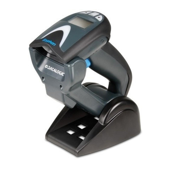
Datalogic Gryphon I GM4100 Quick Reference Manual
General purpose handheld linear imager barcode reader
Hide thumbs
Also See for Gryphon I GM4100:
- Reference manual (428 pages) ,
- Product reference manual (370 pages) ,
- Quick reference manual (56 pages)

Related Manuals for Datalogic Gryphon I GM4100


Summary of Contents for Datalogic Gryphon I GM4100
- Page 1 Gryphon™ I GM4100 General Purpose Handheld Linear Imager Barcode Reader Quick Reference Guide...
- Page 2 Datalogic and the Datalogic logo are registered trademarks of Datalogic S.p.A. in many countries, including the U.S.A. and the E.U. All other brand and product names may be trademarks of their respective owners.
-
Page 3: Table Of Contents
Table of Contents Statement of Agency Compliance ............1 FCC Class B Compliance Statement ..........1 FCC RF Radiation Exposure Statement ......1 Canadian Notice .................. 2 Software Product Policy ................6 Customers Under Software Support ........... 6 Setting Up the Reader ................. 7 Battery Safety .................. - Page 4 NOTES...
-
Page 5: Statement Of Agency Compliance
Gryphon™ I GM4100 Quick Reference Guide Statement of Agency Compliance This device complies with part 15 of the FCC Rules. Operation is subject to the following two conditions: (1) this device may not cause harmful interference, and (2) this device must accept any in- terference received, including interference that may cause unde- sired operation. -
Page 6: Canadian Notice
Statement of Agency Compliance Canadian Notice This equipment does not exceed the Class B limits for radio noise emissions as described in the Radio Interference Regulations of the Canadian Department of Communications. Le present appareil numerique n’emet pas de bruits radioelec- triques depassant les limites applicables aux appareils numeriques de la classe B prescrites dans le Reglement sur le brouillage radio- electrique edicte par le ministere des Communications du Cana-... -
Page 7: End User License Agreement
This End User Software License Agreement ("Agreement") is a legally binding agree- ment governing the licensing of the Software and Documentation by Datalogic Scan- ning, Inc. and its Affiliates ("Datalogic") to the entity or person who has purchased or otherwise acquired a Datalogic Product ("End User"). For purposes of this Agreement, any software that is associated with a separate end-user license agreement is licensed to you under the terms of that license agreement. - Page 8 End User shall not sell, assign, sublicense, distribute, lend, rent, give, or other- wise transfer the Datalogic Product to any third party unless such third party agrees with Datalogic in writing to be bound by the terms and conditions of this Agreement. Any such transfer of the Datalogic Product absent such agree- ment shall be null and void.
- Page 9 Datalogic Scanning, Inc., Legal Department, 959 Terry Street, Eugene, OR 97402. In the defense or settlement of any such claim, Datalogic may, at its option, 1) procure for End User the right to continue using the Datalogic Product, 2)
-
Page 10: Software Product Policy
State of Oregon located in either Multnomah or Lane counties shall have exclusive jurisdiction over all matters regarding this Agree- ment, except that Datalogic shall have the right, at its absolute discretion, to initiate proceedings in the courts of any other state, country, or territory in which End User resides, or in which any of End User's assets are located. -
Page 11: Setting Up The Reader
To install, charge and/or do any other action on the battery, fol- low the instructions in this manual. Before installing the Battery, read “Battery Safety” on the following pages. Datalogic recommends annual replacement of rechargeable battery packs to ensure maximum performance. - Page 12 Setting Up the Reader Do not discharge the battery using any device except for the scanner. When the battery is used in devices other than the designated product, it may damage the battery or reduce its life expectancy. If the device WARNING causes an abnormal current to flow, it may cause the battery to become hot, explode or ignite and cause...
- Page 13 Always charge the battery at 32° – 104°F (0° - 40°C) tem- perature range. Use only the authorized power supplies, battery pack, chargers, and docks supplied by your Datalogic reseller. CAUTION The use of any other power supplies can damage the device and void your warranty.
-
Page 14: Install The Batteries
Setting Up the Reader Install the Batteries Before installing the Battery, read “Battery Safety” on the preceding pages. Datalogic recommends annual replacement of rechargeable battery packs to ensure maximum performance. NOTE To install or change the battery of your reader, you must: With a screwdriver, unscrew the battery cover screw. - Page 15 Setting Up the Reader Carefully lift out the gold contacts circuit, and remove the battery holder while letting the white connector pass through the hole in the battery holder (as shown in the picture below). Pass-through hole Remove the old battery from its place (if present), and insert the new battery in the same position.
-
Page 16: Configuring The Base Station
Configuring the Base Station Configuring the Base Station The base charger/station may be configured in desk application to hold the reader in two different positions, either a horizontal or standing position, in order to provide the most comfortable use depending on needs. Horizontal Standing Changing the Base Station Position... - Page 17 Configuring the Base Station Using your thumbs, push open the plastic tabs on the bottom of the base to free the wing holders. The stand can now be repositioned in either horizontal or standing position. Horizontal Standing Quick Reference Guide...
-
Page 18: Connecting The Base Station
Configuring the Base Station Connecting the Base Station Figure 1 shows how to connect the Base Station to a terminal, PC or other host device. Turn off the host before connection and con- sult the manual for that equipment (if necessary) before proceed- ing. - Page 19 Configuring the Base Station Figure 2. Options for routing the DC cord Please refer to the arrows depicted on the bottom of the base when placing the cables, detailed in Figure 3. Figure 3. Arrows showing routing Verify before connection that the reader’s cable Host Connection: type is compatible with your host equipment.
- Page 20 Configuring the Base Station Figure 4. Connecting to the Host or... or... or... Plug the AC Adapter in to an approved AC Power Connection : wall socket with the cable facing downwards (as shown in Figure 1) to prevent undue strain on the socket. Gryphon Mobile can also be Powered by the Terminal.
-
Page 21: Linking The Reader To A Base Station
Linking the Reader to a Base Station Linking the Reader to a Base Station RF Devices For RF devices, before configuring the interface it is necessary to link the handheld with the base. To link the handheld and the base, press the trigger to wake it and place it on the base. - Page 22 System and Network Layouts Figure 7. Multiple Reader Layout In stand alone systems, each cradle is connected to a single Host. Figure 8. Multiple Stand Alone Layouts Many stand alone connections can operate in the same physical area without interference, provided all readers and cradles in the system have different addresses.
-
Page 23: Using The Bc40Xx™ Radio Base
Charge completed is not correctly placed onto the Base. A button is available to force device connection via the Datalogic Aladdin Software tool, and for paging the scanner when bidirec- tional connection is activated. Refer to the Gryphon I Product Reference Guide (PRG) for a more detailed explanation. -
Page 24: Display
Programming Display The Gryphon I is also available with an optional Display. The FSTN Display with white LED backlight provides additional in- formation. Figure 10. Gryphon™ I Display Programming The reader is factory-configured with a set of standard default fea- tures. -
Page 25: Select The Interface Type
Programming Select the Interface Type Upon completing the physical connection between the reader and its host, proceed directly to Interface Selection on page 22 for in- formation and programming for the interface type the reader is connected to (for example: RS-232, Keyboard Wedge, USB, etc.) and scan the appropriate barcode to select your system’s correct interface type. -
Page 26: Interface Selection
Interface Selection Interface Selection Each reader model will support one of the following sets of host interfaces: RS-232, RS-232 OPOS, USB, Key- General Purpose Models: board Wedge RS-232, RS-232 OPOS, USB, IBM Retail Point of Sale Models : 46XX Configuring the Interface Scan the programming barcode which selects the appropriate in- terface type matching the system the reader will be connected to. - Page 27 USB Com to simulate RS-232 standard interface Select USB-COM-STD IBM-46xx Port 5B reader interface Select IBM-P5B IBM-46xx Port 9B reader interface Select IBM-P9B USB-OEM USB-OEM (can be used for OPOS/UPOS/JavaPOS) Select USB-OEM a. Download the correct USB Com driver from www.datalogic.com Quick Reference Guide...
- Page 28 Interface Selection KEYBOARD AT, PS/2 25-286, 30-286, 50, 50Z, 60, 70, 80, 90 & 95 w/ Standard Key Encoding Select KBD-AT Keyboard Wedge for IBM AT PS2 with standard key encoding but without external keyboard Select KBD-AT-NK AT, PS/2 25-286, 30-286, 50, 50Z, 60, 70, 80, 90 & 95 w/Alternate Key Select KBD-AT-ALT Keyboard Wedge for IBM AT PS2 with alternate key encoding but without exter-...
- Page 29 Interface Selection KEYBOARD (continued) PC/XT w/Standard Key Encoding Select KBD-XT Keyboard Wedge for IBM Terminal 3153 Select KBD-IBM-3153 Keyboard Wedge for IBM Terminals 31xx, 32xx, 34xx, 37xx make only keyboard Select KBD-IBM-M Keyboard Wedge for IBM Terminals 31xx, 32xx, 34xx, 37xx make break keyboard Select KBD-IBM-MB Quick Reference Guide...
-
Page 30: Wand Emulation
Interface Selection KEYBOARD (continued) Keyboard Wedge for DIGITAL Terminals VT2xx, VT3xx, VT4xx Select KBD-DIG-VT USB Keyboard with standard key encoding Select USB Keyboard USB Keyboard with alternate key encoding Select USB Alternate Keyboard USB Keyboard for Apple computers Select USB-KBD-APPLE WAND EMULATION Wand Emulation Select WAND... -
Page 31: Keyboard Interface
Keyboard Interface Keyboard Interface Use the programming barcodes to select options for USB Key- board and Wedge Interfaces. Standard Factory Settings Reference the Gryphon™ I GD4100/GM4100 Product Refer- ence Guide (PRG) for a listing of standard factory settings. Scancode Tables Reference the Gryphon™... - Page 32 Country Mode COUNTRY MODE ENTER/EXIT PROGRAMMING MODE Country Mode = U.S. Country Mode = Belgium Country Mode = Britain Country Mode = Croatia* *Supports only the interfaces listed in the Country Mode feature description Gryphon™ I GM4100...
- Page 33 Country Mode COUNTRY MODE (continued) Country Mode = Czechoslovakia* Country Mode = Denmark* Country Mode = France Country Mode = Germany Country Mode = Hungary* Country Mode = Italy *Supports only the interfaces listed in the Country Mode feature description Quick Reference Guide...
- Page 34 Country Mode COUNTRY MODE (continued) Country Mode = Japanese 106-key* Country Mode = Norway* Country Mode = Poland* Country Mode = Portugal* Country Mode = Romania* Country Mode = Slovakia* *Supports only the interfaces listed in the Country Mode feature description Gryphon™...
- Page 35 Country Mode COUNTRY MODE (continued) Country Mode = Spain Country Mode = Sweden Country Mode = Switzerland* *Supports only the interfaces listed in the Country Mode feature description Quick Reference Guide...
-
Page 36: Caps Lock State
Caps Lock State Caps Lock State This option specifies the format in which the reader sends charac- ter data. This applies to keyboard wedge interfaces. This does not apply when an alternate key encoding keyboard is selected. ENTER/EXIT PROGRAMMING MODE Caps Lock State = Caps Lock OFF Caps Lock State = Caps Lock ON Caps Lock State = AUTO Caps Lock Enable... -
Page 37: Numlock
Numlock Numlock This option specifies the setting of the Numbers Lock (Numlock) key while in keyboard wedge interface. This only applies to alter- nate key encoding interfaces. It does not apply to USB keyboard. ENTER/EXIT PROGRAMMING MODE Numlock = Numlock key unchanged Numlock = Numlock key toggled Quick Reference Guide... -
Page 38: Technical Specifications
Technical Specifications Technical Specifications The following table contains Physical and Performance Charac- teristics, User Environment and Regulatory information. Item Description Physical Characteristics White/Gray Color Black/Gray Height 7.1”/181 mm Dimensions Length 3.9”/100 mm Width 2.8”/71 mm Approximately Weight (without cable) 8.7 ounces/246 g (reader with display) 8.7 ounces/246 g (base charger) Electrical Characteristics Battery Type... - Page 39 Technical Specifications Item Description Print Contrast Minimum 15% minimum reflectance UPC/EAN/JAN, P2 /P5 add-ons; Code 39; Italian Pharmacode 39; Code 128; C128 ISBT; Code 128 add- ons; I 2 of 5; Standard 2 of 5; Code 11;Codabar; EAN Decode Capability 128;...
- Page 40 Technical Specifications Item Description Regulatory Electrical Safety UL 60950, CSA C22.2 No. 60950, IEC 60950 433 MHz model 910 MHz model Europe - CE, Russia – Gost; USA/Canada – FCC/IC; Australia – Ctick; Pending: China – SRRC; EMI/RFI Mexico – NOM + Cofetel Singapore –...
-
Page 41: Led And Beeper Indications
LED and Beeper Indications LED and Beeper Indications The reader’s beeper sounds and its LED illuminates to indicate various functions or errors on the reader. An optional “Green Spot” also performs useful functions. The following tables list these indications. One exception to the behaviors listed in the ta- bles is that the reader’s functions are programmable, and may or may not be turned on. - Page 42 LED and Beeper Indications INDICATION DESCRIPTION BEEPER The reader has Reader The LED blinks been disabled by Disabled continuously the host. While in Stand Mode or Trigger Stand Mode the Green Spot is on green spot shall continuously be on while in stand watch state.
-
Page 43: Error Codes
Error Codes INDICATION DESCRIPTION BEEPER Configuration option(s) have Reader sounds Label Program- been successfully one high fre- ming Mode programmed via quency beep and Acceptance of labels and the 4 low frequency Programming reader has exited beeps followed Programming by reset beeps. Mode. -
Page 44: Base Station Indications
Base Station Indications Base Station Indications INDICATION LEDS Power-up Complete Yellow LED on Reader Disabled by the HOST or the com- Yellow LED blinking ~1Hz munication with HOST is not established Yellow LEDs turned off for Data/labels are transmitted to the HOST 100mSec Programming Mode Yellow LED blinks quickly... -
Page 45: Ergonomic Recommendations
All models are designed to be compliant with rules and regula- tions in locations they are sold and will be labeled as required. Any changes or modifications to equipment, not expressly ap- proved by Datalogic could void the user's authority to operate the equipment. Power Supply... -
Page 46: Imager Labeling
Regulatory Information Imager Labeling Labels are shown here to illustrate their location only. Please view the labels on your product for actual details. Scanner Regulatory Label Base Station Label Gryphon™ I GM4100... -
Page 47: Weee Statement
Waste Electrical and Electronic Equipment (WEEE) Statement English For information about the disposal of Waste Electrical and Electronic Equipment (WEEE), please refer to the website at www.scanning.datalogic.com. Italian Per informazioni sullo smaltimento delle apparecchiature elettriche ed elettroniche consultare il sito Web www.scanning.datalogic.com. -
Page 48: Warranty
Datalogic. Risk of Loss Customer shall bear risk of loss or damage for product in transit to Datalogic. Data- logic shall assume risk of loss or damage for product in Datalogic's possession or product being returned to Customer by Datalogic, except such loss or damage as may be caused by the negligence of Customer, its agents or employees. - Page 49 Warranty NOTES Quick Reference Guide...
- Page 50 Warranty NOTES Gryphon™ I GM4100...
-
Page 51: Declaration Of Conformity
DECLARATION OF CONFORMITY EC-056 Rev.: 0 Pag.: 1 di 1 Datalogic Scanning Group Srl Via S. Vitalino, 13 Lippo di Calderara di Reno (BO) 40012 Italy dichiara che declares that the déclare que le bescheinigt, daß das Gerät declare que el Gryphon GM 41xx ;... - Page 52 Datalogic Scanning, Inc Telephone: [33].01.64.86.71.00 Telephone: (305) 591-3222 france.scanning@datalogic.com latinamerica.scanning@datalogic.com Germany Singapore Datalogic Scanning GmbH Datalogic Scanning Singapore PTE LTD Telephone: 49 (0) 61 51/93 58-0 Telephone: (65) 6435-1311 germany.scanning@datalogic.com singapore.scanning@datalogic.com India Iberia Datalogic Scanning India Datalogic Scanning SAS Sucursal en Telephone: 91- 22 - 64504739 España...