
Related Manuals for Smooth Fitness 9.45ST


Summary of Contents for Smooth Fitness 9.45ST
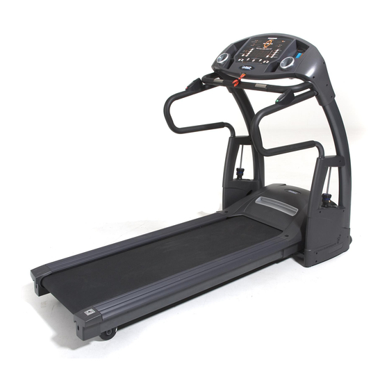
- Page 1 USER’S MANUAL 9.45ST MOTORIZED TREADMILL USER WEIGHT LIMITATION: 400lbs(182kgs). SERIAL NUMBER (found on frame):...
- Page 2 9.45ST TREADMILL PRECAUTIONS For future service or related questions: Please staple your receipt and/or write in the name and phone number of the retail store where you purchased your treadmill. Name: ______________________________ Phone Number: ___________________ Receipt: ______________________ Precautions: WARNING: To reduce the risk of burns, fire, electric shock, or injury to persons, read the following important precautions and information before operating the treadmill.
-
Page 3: Power Requirements
www.smoothfitness.com POWER REQUIREMENTS Power Requirements: IMPROPER CONNECTION OF THE EQUIPMENT GROUNDING CONNECTOR CAN RESULT IN THE RISK OF AN ELECTRIC SHOCK. CHECK WITH A QUALIFIED ELECTRICIAN OR SERVICE MAN IF YOU ARE IN DOUBT AS TO WHETHER THE PRODUCT IS PROPERLY GROUNDED. DO NOT MODIFY THE PLUG PROVIDED WITH THE PRODUCT, IF IT WILL NOT FIT THE OUTLET;... -
Page 4: Before You Begin
9.45ST TREADMILL BEFORE YOU BEGIN Open the boxes: Open the boxes of your new equipment. Inventory all parts included in the boxes, and compare them to the Supplied Components and Supplied Hardware lists on pages 5-6 for a full count of the parts included. If you are missing any parts or have any questions contact us directly at 888-800-1167 *Assembly instructions are on pages 18-26. -
Page 5: Supplied Components
www.smoothfitness.com SUPPLIED COMPONENTS This list identifies the major components you will use to assemble this product. Description Qty. Computer Front Handlebar Assembly Handlebar Upright Assembly Left Upright Assembly Right Main Frame Assembly Chest Belt Power Cord Running belt Lubrication Adjustable Cylinder Upright Cover - LL Upright Cover - LR Upright Cover - RL... -
Page 6: Supplied Hardware
9.45ST TREADMILL SUPPLIED HARDWARE This list identifies the hardware you will use to assemble the product. To help distinguish between the various types of screws and bolts, use the scale below to measure them and compare them to the sizes listed. Description Qty. -
Page 7: Complete Parts List
www.smoothfitness.com COMPLETE PARTS LIST Item No. Description Qty. Part No. Complete Computer Console 9.45ST-100 Overlay 9.45ST-101 Computer Insert 9.45ST-102 Console PC Board 9.45ST-103 Console Housing – Upper 9.45ST-104 Console Housing – Bottom 9.45ST-105 Safety Key Base 9.45ST-106 Safety Key 9.45ST-107 Safety Key Wire –... - Page 8 9.45ST TREADMILL COMPLETE PARTS LIST Item No. Description Qty. Part No. Adjustable Cylinder 9.45ST-310 Upright Plastic Shroud – LL 9.45ST-311 Upright Plastic Shroud – LR 9.45ST-312 Upright Plastic Shroud – RL 9.45ST-313 Upright Plastic Shroud – RR 9.45ST-314 Adjustable Cylinder Cover - Upper 9.45ST-315 Fixing Inserts 9.45ST-316...
- Page 9 www.smoothfitness.com COMPLETE PARTS LIST Item No. Description Qty. Part No. Elevation Support Tube 9.45ST-509 Elevation Support Tube Cover - LEFT 9.45ST-510 Motor Bottom Cover 9.45ST-511 Deck Frame Side Cover - LEFT 9.45ST-512 Plastic Clamp - TOP 9.45ST-513 Plastic Clamp - BOTTOM 9.45ST-514 Elevation Support 9.45ST-515...
- Page 10 9.45ST TREADMILL COMPLETE PARTS LIST Item No. Description Qty. Part No. M8 × 15mm Bolt 9.45ST-804 M8 × 50mm Bolt 9.45ST-805 # 8 × 20mm Screw 9.45ST-806 4 × 15mm Thread Cutting Screw 9.45ST-807 M5 × 10mm Screws 9.45ST-808 M8 × 16 Screws 9.45ST-809 Washer 9.45ST-813...
-
Page 11: Parts Diagram
www.smoothfitness.com PARTS DIAGRAM MOST OF THE PARTS SHOWN HERE HAVE BEEN PRE-ASSEMBLED... - Page 12 9.45ST TREADMILL PARTS DIAGRAM MOST OF THE PARTS SHOWN HERE HAVE BEEN PRE-ASSEMBLED.
- Page 13 www.smoothfitness.com PARTS DIAGRAM A MAJORITY OF THE PARTS SHOWN HERE HAVE BEEN PREASSEMBLED AT THE FACTORY.
- Page 14 9.45ST TREADMILL PARTS DIAGRAM MOST OF THE PARTS SHOWN HERE HAVE BEEN PRE-ASSEMBLED.
- Page 15 www.smoothfitness.com PARTS DIAGRAM MOST OF THE PARTS SHOWN HERE HAVE BEEN PRE-ASSEMBLED.
- Page 16 9.45ST TREADMILL PARTS DIAGRAM MOST OF THE PARTS SHOWN HERE HAVE BEEN PRE-ASSEMBLED.
- Page 17 www.smoothfitness.com PARTS DIAGRAM MOST OF THE PARTS SHOWN HERE HAVE BEEN PRE-ASSEMBLED.
- Page 18 (B)Remove the treadmill and all the components and hardware from the box. (C)Check the quantities of all components and hardware with the component and hardware lists on pages 5-6 (D) After verifying inventory if there are any missing parts please contact Smooth fitness at 1-888-800-1167.
- Page 19 www.smoothfitness.com ASSEMBLY STEP 2:Assemble Upright Frame NOTE: Make sure all wires are recessed into the frame. DO NOT trap or pinch DO NOT tighten bolts until STEP9 (A) Connect the Lower and middle section wire as seen below (307 to 402)(308 to 403) (B) Insert any extra cable length into the Left Upright (301).
- Page 20 9.45ST TREADMILL ASSEMBLY STEP 3: Assemble The Side Handlebars NOTE: Side rails are interchangeable for use on both right and left sides. Make sure all wires recessed into the frame. DO NOT trap or pinch. (A) Connect the Left Motion Control lower wire to the middle wire (207 to 309 ). As Shown in the diagram below.
- Page 21 www.smoothfitness.com ASSEMBLY STEP 4: Assemble Front Handlebar (A) Place the front handlebar (203) on top of the left and right uprights (301) (B) Now secure the front handle bar with four M8 x 50mm bolts(805) (C) Tighten all handlebar hardware (be sure not to pinch wires).
- Page 22 9.45ST TREADMILL ASSEMBLY STEP 5: Attaching the Upright Cover and Connect Computer Cable NOTE: BE CAREFUL NOT TO DAMAGE THE WIRES WHEN SECURING THE UPRIGHT COVERS. (A) Attach the Right Upright Cover (304) to the right upright (301). 4 × 15mm Thread Cutting Screw(807) (B) Secure the Right Upright Cover with two (C) Repeat the above process for the left side.
- Page 23 www.smoothfitness.com ASSEMBLY STEP 6: Attach the Outside Upright Covers NOTE: CAREFULLY FOLD THE COMPUTER CABLES AND TUCK THEM BETWEEN THE PLASTIC RIDGES OF PARTS 304 AND 305 SO THEY WILL NO BE PINCHED. 4 × 15mm Thread Cutting Screw (A) Secure the ground wire onto the Right upright with one (807).
-
Page 24: Adjustable Cylinder
9.45ST TREADMILL ASSEMBLY STEP 7: Attach adjustable cylinder to treadmill frame WARNING: THE PATENTED HYDRASUSPENSION SYSTEM REQUIRES THE ADJUSTABLE CYLINDER TO BE TIGHT FITTING. PLEASE BE PATIENT WITH THIS ASSEMBLY STEP. (A) Put Adjustable Cylinder Cover-Upper (315) into Adjustable Cylinder (310). (B) Attach the bottom of the Adjustable Cylinder (310) to the left Cylinder Mounting Shaft (509) and secure with one washer (846) and one M8 nylon nut (826). -
Page 25: Upright Plastic Shroud - Ll
www.smoothfitness.com ASSEMBLY Assembly front plastic shrouds STEP 8: (A) Attach the outer Left Upright Plastic Shroud - LL (311) , the inner Left Upright Plastic Shroud - LR (312) and the Adjustable Cylinder Cover – Upper(315)to the Left 4 × 15mm Thread Upright - L (301) and secure with five M8 x 20mm Screws (806) and five Cutting Screw (807). - Page 26 9.45ST TREADMILL ASSEMBLY STEP 9:Securing of the Upright Tubes NOTE: ONLY TURN BOLTS CLOCKWISE. The Allen Bolt Sets (412) have been pre-assembled in the Base Frame(401). (A) Secure The Upright Tubes by tightening the Allen Bolt (412), located in the Upright Tube, clockwise.
-
Page 27: Stabilizer Adjustment
www.smoothfitness.com STABILIZER ADJUSTMENT FOLLOW THESE INSTRUCTIONS TO LEVEL YOUR TREADMILL: An uneven floor or improper stabilizer level can cause the treadmill to wobble during use as well as the incline adjustment to function incorrectly. Please follow the procedure described below to make sure the treadmill stabilizer is adjusted correctly prior to use. -
Page 28: Safety Key
9.45ST TREADMILL FEATURES Serial Number Location Insert safety key The safety key must be inserted for the treadmill to function. The safety key clip should be worn at all times when the treadmill is in use. This safety feature is designed to prevent injury. - Page 29 www.smoothfitness.com MOTION CONTROL OPERATION MOTION CONTROL: Walking belt speed can be increased, decreased or stopped using the Motion Control sensors on the handlebars. To do this follow the instructions below: Press the button on the console to switch the motion control function on and off: •...
- Page 30 Repeat the above procedure until the walking belt is not slipping. The tension should be just tight enough not to slip. If proper tension cannot be achieved within four attempts please contact Smooth Fitness Technical Support. Belt centering may be necessary once you have completed the tensioning procedure.
- Page 31 Every 2 months of operation lift the sides of the walking belt and feel the top surface of the running deck as far as you can reach. If you feel signs of silicone, no further lubrication is required. If it feels dry to the touch, follow the instructions below. . To purchase lubricant Kit please contact Smooth Fitness 1-888-800-1167 To apply lubricant under the walking belt: Position the walking belt so that the seam is located on top and in center of the walking board.
-
Page 32: Important Steps
9.45ST TREADMILL IMPORTANT STEPS Warning: Before using this product, please consult your personal physician for a complete physical examination. Frequent and strenuous exercise should be approved by your doctor first. If any discomfort should result from your use of this product, stop exercising and consult your doctor. -
Page 33: Target Heart Rate
www.smoothfitness.com TARGET HEART RATE Finding your pulse: To make sure your heart is beating in its target zone, you’ll need to know how to monitor your heart rate. The easiest way is to feel the pulse in the carotid artery on either side of your neck, between the windpipe and the large neck muscles. Count the number of beats in ten seconds, and then multiply that number by six. -
Page 34: Muscle Chart
9.45ST TREADMILL MUSCLE CHART Targeted muscle groups: The exercise routine that is performed on this product will develop primarily lower body muscle groups. These muscle groups are shown in gray color on the chart below. MUSCLE GROUPS Shoulder muscles Calf muscles Pectoral muscles Trapezius muscles Bicep muscle... -
Page 35: Stretching Routine
www.smoothfitness.com STRETCHING ROUTINE Warm up and cool down: A successful exercise program consists of a warm-up, aerobic exercise, and a cool-down. Do the entire program at least two and preferably three times a week, resting for a day between workouts. After several months, you can increase your workouts to four or five times per week. - Page 36 Procedure for Obtaining Your Remedy Under This Warranty: To obtain service on a Smooth Fitness product, call Smooth Fitness. In the instance that service is not available in an area, Smooth Fitness, at its discretion, can either 1) find a service technician in your area to perform warranty service, 2) have a local dealer perform warranty service, or 3) send the warranty parts to you and reimburse as described above.
-
Page 37: Troubleshooting
www.smoothfitness.com TROUBLESHOOTING NOTE: Do not touch any internal electric wires without consulting the manufacturer. Treadmill will not start: Symptom Resolution Check the following: Make sure the power cord is plugged into a surge protector, the surge protector is plugged into a properly grounded outlet and the surge protector is turned on (refer to the Power Requirements section in this manual). - Page 38 Smooth Fitness 112 Gaither Drive Mt. Laurel, NJ 08054 Toll Free Customer Service: 1.888.800.1167 Website: www.smoothfitness.com...