Advertisement
Available languages
Available languages
Quick Links
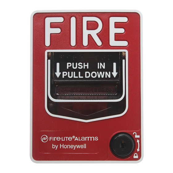
BG-12 Series Manual Pull Stations
Document: 50964 Revision: B ECN: 98-461 08/04/99
Description
The BG-12 Series Pull Stations are non-coded manual pull
stations which provide a Fire Alarm Control Panel (FACP)
with a single alarm initiating input signal. The BG-12 series
includes both single-action and dual-action models equipped
with either a hex or key lock / reset. A single-action pull-
station is activated by a single pull-down of the alarm handle.
The dual-action versions require pushing in the handle, then
pulling the handle down for activation. The BG-12 series
manual pull stations are UL listed and meet the ADA require-
ment of a 5-lb. maximum pull force to activate. Operating
instructions are molded into the handle along with Braille
text. Molded terminal numbers can be found adjacent to the
wiring terminals.
BG-12 Series Models available:
BG-12S – Single action with 'pigtail' connections and a hex
lock reset. Pigtail wires are provided for connection to the
FACP Initiating Device Circuit (IDC).
BG-12 – Dual action model with screw terminal connections
and a hex lock reset.
BG-12L – Same as BG-12 except with a key lock reset.
BG-12LSP – Same as BG-12L except with both English and
Spanish operating instructions.
Dual Action BG-12L
Switch Contact Rating
All switch contacts are rated for 0.25 A at 30 volts (AC or DC).
Installation
Surface mount the BG-12 pull station to a SB-10 surface backbox.
Semi-flush mount the BG-12 to a standard single gang, double-gang,
or 4-inch (10.16cm) square electrical box. Mount the optional Trim
Ring (BG-TR) if necessary when semi-flush mounting the unit.
The word 'ACTIVATED'
is displayed
If, during mounting of the pull station, the door becomes de-
tached, complete the following steps to reattach the door to the
backplate. The door cannot be connected to the pull station if the
unit is mounted to the backbox.
1.
Position the door and backplate side by side in the full open
position. (i.e. 180-degrees with respect to each other.)
2.
With the backplate position fixed, move the door behind the
backplate, as shown in the illustration below, part A.
3.
Align the hinge posts and holes by bringing the door up to meet
the backplate, paying particular attention to the 'keying' that
occurs when the door's post hole is aligned to the backplate's
hinge post. Refer to the illustration, part B.
4.
With the two pieces aligned and 'keyed' together, slide the holes
down onto the posts. Refer to the illustration, part C.
5.
Holding the backplate, close the door slightly to lock the door
and backplate together.
1 4
1 3
1 2
1 1
1 0
9
P/ N 5099 7 REV.
REFER TO D OCU MENT
NUMB ER 5 1 015 RE V.
D O O R K E Y S IN T O
B A C K P LA T E AT TH IS PO IN T
B
P O S T
H O LE
P O S T
C
DOOR MATED TO BACKPLATE
on the pull station's
pulled-down handle
DOOR ATTACHMENT
With the door and
backplate aligned and
'keyed' together, slide
the holes down onto
the posts.
LOOP
A DD R ESS
A
H O LE
P O S T
1 3
1 2
11
1 0
P/N 509 97 REV.
REFER TO DOC U MENT
NUMBER 5101 5 RE V .
Closing the door slightly
locks the door and
backplate together.
LOOP
A DDR ESS
Advertisement

Related Manuals for Fire-Lite BG-12 Series


Summary of Contents for Fire-Lite BG-12 Series
- Page 1 Position the door and backplate side by side in the full open Dual Action BG-12L position. (i.e. 180-degrees with respect to each other.) BG-12 Series Manual Pull Stations With the backplate position fixed, move the door behind the backplate, as shown in the illustration below, part A.
- Page 2 F ro m FAC P 1 2 3 4 5 6 To Next A dd resable D evice 1 2 3 4 5 6 ‘Pigtails’ Black in/out (-) Red in\out (+) 1 2 3 4 5 6 BLACK S T R IP G A U G E STR IP G AU G E Single Action BG-12S Dual Action BG-12L (Shown Activated)
- Page 3 Parámetros de Contacto del Interruptor Todos los contactos de interruptor son clasificados para 0.25 A en 30 voltios (AC o DC). Instalación Instale en la superficie la estación BG-12 a una caja posterior de superficie SB-10. Instale semi empotrada la BG-12 a una caja eléctrica cuadrada de 4- pulgadas (10.16cm) de grupo doble o singular.
- Page 4 1 2 3 4 5 6 7 8 9 0 1 2 3 4 5 6 7 8 9 0 1 2 3 4 5 6 7 8 9 0 1 2 3 4 5 6 7 8 9 0 1 2 3 4 5 6 7 8 9 0 1 2 3 4 5 6 7 8 9 0 1 2 3 4 5 6 7 8 9 0...