
Related Manuals for UNI-T UT203


Summary of Contents for UNI-T UT203
- Page 1 UT203/204 Digital Clamp Multimeters P/N: 41416301 Registered Design No.: ZL02 3 357791.6...
-
Page 2: Table Of Contents
Model UT203/204: OPERATING MANUAL Table of Contents Title Page Overview Unpacking Inspection Safety Information Rules For Safe Operation International Electrical Symbols The Meter Structure Rotary Switch Functional Buttons The Effectiveness of Functional Buttons Display Symbols Measurement Operation A. DC/AC Voltage Measurement B. - Page 3 Model UT203/204: OPERATING MANUAL Title Page Sleep Mode Specifications A. General Specifications B. Environmental Requirements Accuracy Specifications A. DC Voltage B. AC Voltage C. Resistance D. Diode Test E. Continuity Test F. Frequency G. Duty Cycle H. DC Current I. AC Current Maintenance A.
-
Page 4: Overview
Model UT203/204: OPERATING MANUAL Overview This Operating Manual covers information on safety and cautions. Please read the relevant information carefully and observe all the Warnings and Notes strictly. Warning To avoid electric shock or personal injury, read the “Safety Information” and “Rules for Safe Operation”... -
Page 5: Unpacking Inspection
Model UT203/204: OPERATING MANUAL Unpacking Inspection Open the package case and take out the Meter. Check the following items carefully to see any missing or damaged part: Item Description English Operating Manual 1 piece Test Lead 1 pair Test Clip 1 pair Carrying Bag 1 piece... -
Page 6: Safety Information
Model UT203/204: OPERATING MANUAL Safety Information This Meter complies with the standards IEC61010: in pollution degree 2, overvoltage category (CAT. II 600V, CAT. III 300V) and double insulation. CAT. II: Local level, appliance, PORTABLE EQUIPMENT etc., with smaller transient overvoltages than CAT. III. CAT. -
Page 7: Rules For Safe Operation
Model UT203/204: OPERATING MANUAL Rules For Safe Operation Warning To avoid possible electric shock or personal injury, and to avoid possible damage to the Meter or to the equipment under test, adhere to the following rules: Before using the Meter inspect the case. Do not use the Meter if it is damaged or the case (or part of the case) is removed. - Page 8 Model UT203/204: OPERATING MANUAL The rotary switch should be placed in the right position and no any changeover of range shall be made during measurement is conducted to prevent damage of the Meter. Do not carry out the measurement when the Meter’s back case and battery compartment are not closed to avoid electric shock.
- Page 9 Model UT203/204: OPERATING MANUAL When servicing the Meter, use only the same model number or identical electrical specifications replacement parts. The internal circuit of the Meter shall not be altered at will to avoid damage of the Meter and any accident. Soft cloth and mild detergent should be used to clean the surface of the Meter when servicing.
-
Page 10: International Electrical Symbols
Model UT203/204: OPERATING MANUAL International Electrical Symbols AC (Alternating Current) DC (Direct Current) AC or DC Grounding Double Insulated Warning. Refer to the Operating Manual Deficiency of Built-In Battery Continuity Test Diode Fuse Conforms to Standards of European Union... -
Page 11: The Meter Structure
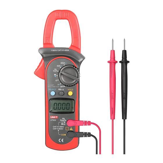
Model UT203/204: OPERATING MANUAL The Meter Structure (see figure 1) Input Terminals LCD Display Functional Buttons Rotary Switch Trigger: press the lever to open the transformer jaws. When the pressure on the lever is released, the jaws will close. Hand Guards: to protect user’s hand from touching the dangerous area. -
Page 12: Rotary Switch
Model UT203/204: OPERATING MANUAL Rotary Switch Below table indicated for information about the rotary switch positions. Rotary Switch Position Function Power is turned off AC or DC voltage measurement Resistance measurement : Diode test : Continuity test Hz / Duty% Frequency Measurement and Duty Measurement &... -
Page 13: Functional Buttons
Model UT203/204: OPERATING MANUAL Functional Buttons Below table indicated for information about the functional button operations. Button Operation Performed HOLD Press HOLD to enter the Hold mode in any mode, the Meter beeps. Press HOLD again to exit the Hold mode, the Meter beeps. range: Press to select manual ranging measurement mode. - Page 14 Model UT203/204: OPERATING MANUAL Button Operation Performed SELECT Press SELECT button to select the alternate functions marked in blue colour on the Meter’s faceplate including Hz, Duty%, , and 400 , 40 After the Meter entering Sleep Mode, press and hold SELECT to turn the Meter on, it will disable the Sleep Mode feature.
-
Page 15: The Effectiveness Of Functional Buttons
Model UT203/204: OPERATING MANUAL The Effectiveness of Functional Buttons Not every functional buttons can be used on every rotary switch positions. Below table describe which functional buttons can be used on which rotary switch positions Functional Buttons Rotary Switch Positions SELECT HOLD Hz / Duty%... -
Page 16: Display Symbols
Model UT203/204: OPERATING MANUAL Display Symbols (see figure 2) (figure 2) - Page 17 Model UT203/204: OPERATING MANUAL Number Symbol Meaning Indicator for AC voltage or current Indicator for DC voltage The battery is low. Warning: To avoid false readings, which could lead to possible electric shock or personal injury, replace the battery as soon as the battery indicator appears. The Meter is in the auto range mode in which the Meter automatically selects the range with the best resolution.
- Page 18 Model UT203/204: OPERATING MANUAL Number Symbol Meaning ,k ,M : Ohm. The unit of resistance. k : Kilohm. 1x10 3 or 1000 ohms M : Megohm. 1x10 6 or 1,000,000 ohms The unit of Frequency Amperes (amps). The unit of current. mV, V Volts.
-
Page 19: Measurement Operation
Model UT203/204: OPERATING MANUAL Measurement Operation A. DC/AC Voltage Measurement (see figure 3) Warning To avoid harms to you or damages to the Meter from eletric shock, do not attempt to measure voltages higher than 600V AC/DC, although readings may be obtained. Black The DC Voltage ranges are: 400mV, 4V, 40V, 400V and 600V. - Page 20 Model UT203/204: OPERATING MANUAL Set the rotary switch to . DC mesaurement mode and auto ranging is a default. Press SELECT to switch to AC measurement mode or press to switch to manual ranging measurement mode. Connect the test leads across with the object being measured. The measured value shows on the display.
-
Page 21: Measuring Resistance
Model UT203/204: OPERATING MANUAL B. Measuring Resistance (see figure 4) Warning To avoid damages to the Meter or to the devices under test, disconnect circuit power and discharge all the high-voltage capacitors before measuring resistance. The resistance ranges are: 400 , 4k , 40k ,400k ,M and 40M . - Page 22 Model UT203/204: OPERATING MANUAL Note To obtain a more precise reading, you could remove the objects being tested from the circuit when measuring. When resistance measurement has been completed, disconnect the connection between the testing leads and the circuit under test and remove testing leads from the input terminals.
-
Page 23: Testing Diodes
Model UT203/204: OPERATING MANUAL C. Testing Diodes (see figure 5) Warning To avoid damages to the Meter or to the devices under test, disconnect circuit power and discharge all the high-voltage capacitors before testing diodes. Use the diode test to check diodes, transistors, and other semiconductor devices. - Page 24 Model UT203/204: OPERATING MANUAL Set the rotary switch to . Diode measurement mode is a default or presss SELECT to select measurement mode. For forward voltage drop readings on any semiconductor component, place the red test lead on the component’s anode and place the black test lead on the component’s cathode.
-
Page 25: Testing For Continuity
Model UT203/204: OPERATING MANUAL D. Testing for Continuity (see figure 6) Warning To avoid damages to the Meter or to the devices under test, disconnect circuit power and discharge all the high-voltage capacitors before measuring continuity. To test for continuity, connect the Meter as follows: Insert the red test lead into the Hz Duty% Black terminal and the black test lead into the... - Page 26 Model UT203/204: OPERATING MANUAL Note When continuity testing has been completed, disconnect the connection between the testing leads and the circuit under test and remove testing leads from the input terminals.
-
Page 27: Frequency Measurement
Model UT203/204: OPERATING MANUAL E. Frequency Measurement (see figure 7) Warning To avoid harms to you or damages to the Meter from eletric shock, do not attempt to measure voltages higher than 600V AC/DC, although readings may be obtained. The resistance ranges are: 10Hz, 100Hz, 1kHz, 10kHz, 100kHz, 1MHz and Black 10MHz. - Page 28 Model UT203/204: OPERATING MANUAL Note When frequency measurement has been completed, disconnect the connection between the testing leads and the circuit under test, and remove the testing leads away from the input terminals of the Meter.
-
Page 29: Duty Cycle Measurement
Model UT203/204: OPERATING MANUAL F. Duty Cycle Measurement (see figure 8) Warning To avoid harms to you or damages to the Meter from eletric shock, do not attempt to measure voltages higher than 600V AC/DC, although readings may be obtained. The duty cycle range is: 0.1%~99.9%. - Page 30 Model UT203/204: OPERATING MANUAL Note When duty cycle measurement has been completed, disconnect the connection between the testing leads and the circuit under test, and remove the testing leads away from the input terminals of the Meter.
-
Page 31: Dc/Ac Current Measurement
Model UT203/204: OPERATING MANUAL G. DC/AC Current Measurement (see figure 9) The measuremnet ranges of current are: 40.00 and 400.0 To measure current, do the following: 400A Set the rotary switch to 40 or 400 . DC measuremnet mode is a default. Press SELECT to switch between DC and AC measurement mode. - Page 32 Model UT203/204: OPERATING MANUAL Note Press to subtracts a stored value from the present measurement value and displays a result. When current measurement has been completed, disconnect the connection between the conductor under test and the jaw, and remove the conductor away from the transformer jaw of the Meter.
-
Page 33: Sleep Mode
Model UT203/204: OPERATING MANUAL Sleep Mode To preserve battery life, the Meter automatically turns off if you do not turn the rotary switch or press any button for around 15 minutes. The Meter can be activated by turning the rotary switch or pressing the button based on ‘The Effectiveness of Functional Buttons”... -
Page 34: Specifications
Model UT203/204: OPERATING MANUAL Specifications A. General Specifications: Maximum Voltage between any Terminals and grounding: Refer to different range input protection voltage. Display: 3 3/4 digits LCD display, Maximum display 3999 Polarity: Automatically display. Overloading: Display OL or –OL Battery Deficiency: Display Measurement Speed: Updates 3 times/second. -
Page 35: Environmental Requirements
Model UT203/204: OPERATING MANUAL Battery Life: typically 150hours (alkaline battery) Sleep Mode (can be disabled) Dimensions (H x W x L): 208mm x 76mm x 30mm. Weight: Approximate 260g (battery included) B. Environmental Requirements The Meter is suitable for indoor use. Altitude: Operating: 2000m Storage: 10000m Safety/ Compliances: IEC 61010 CAT.II 600V, CAT.III 300V over voltage and... -
Page 36: Accuracy Specifications
Model UT203/204: OPERATING MANUAL Accurate Specifications Accuracy: (a% reading + b digits), guarantee for 1 year. Operating temperature: 23ºC 5ºC Relative humidity: 85%R.H Temperature coefficient: 0.1x(specified accuracy)/1ºC A. DC Voltage Range Resolution Accuracy Overload protection 400.0mV 0.1mV (0.8%+3) 4.000V 600V DC/AC 40.00V 10mV (0.8%+1) -
Page 37: Ac Voltage
Model UT203/204: OPERATING MANUAL B. AC Voltage Range Resolution Accuracy Overload protection 4.000V 40.00V 10mV (1%+5) 600V DC/AC 400.0V 100mV 600V (1.2%+5) Remarks: Input impedance: 10M // less than 100pF Frequency response: 40Hz~400Hz. Change to AC: UT203: Change to AC by using average response method. Input sine wave, then adjust the reading until it is same as the effective value. -
Page 38: Resistance
Model UT203/204: OPERATING MANUAL C. Resistance Range Resolution Accuracy Overload protection 400.0 100m (1.2%+2) 4.000k 600Vp 40.00k (1%+2) 400.0k 4.000M (1.2%+2) 40.00M (1.5%+2) D. Diode Test Range Resolution Accuracy Overload protection Display forward voltage 600Vp drop nearest value Remark: Open circuit voltage approximate 1.48V. -
Page 39: Continuity Test
Model UT203/204: OPERATING MANUAL E. Continuity Test Range Resolution Accuracy Overload protection Around 50 , 100m 600Vp the buzzer beeps Remark: Open circuit voltage approximate 0.45V. The buzzer may or may not beeps when the resistance of a circuit under test is between 50 ~100 The buzzer will not beep when the resistance of a circuit under test is >... -
Page 40: Frequency
Model UT203/204: OPERATING MANUAL F. Frequency Range Resolution Accuracy Overload protection 10Hz 0.001Hz 100Hz 0.01Hz 1kHz 0.1Hz 600Vp (0.1%+3) 10kHz 100kHz 10Hz 1MHz 100Hz For reference only 10MHz 1kHz Remark: Input Sensitivity as follows: When 100kHz: 300mV rms; When > 100kHz: 600mV rms When >... -
Page 41: Duty Cycle
Model UT203/204: OPERATING MANUAL G. Duty Cycle Range Resolution Accuracy Overload protection 0.1%~99.9% 0.1% For reference only 600Vp H. DC Current Range Resolution Accuracy Overload protection 40.00A 0.01A (2%+5) 400A DC/AC 400.0A 0.1A (2%+3) Warning The operating temperature must be 0ºC ~40ºC when measuring current. Remark: If the reading is positive, the current direction is from bottom to up. - Page 42 Model UT203/204: OPERATING MANUAL also to heat and machines reaction force. Any shock will cause the changing in reading in the short time. Follow the below procedure to measure current will be more precise: Hold the Meter tight and press the lever to open the transformer jaw. Center the conductor within the transformer jaws, then release the Meter slowly until the transformer jaw is completely closed.
-
Page 43: Ac Current
Model UT203/204: OPERATING MANUAL I. AC Current Range Resolution Accuracy Frequency Response Overload protection 40.00A 0.01A (2.5%+8) 400A DC/AC 50Hz ~ 60Hz 400.0A 0.1A (2.5%+5) Warning The operating temperature must be 0ºC ~40ºC when measuring current. Remark: It may have 10 digits or less unstable or wrong digits, it will not affect measurement result. - Page 44 Model UT203/204: OPERATING MANUAL Remove the transformer jaw. Press to display zero. Repeat the above 1. procedure. The obtained reading will be more precise. l Change to AC: UT203: Change to AC by using average response method. Input sine wave, then adjust the reading until it is same as the effective value.
-
Page 45: Maintenance
Model UT203/204: OPERATING MANUAL MAINTENANCE This section provides basic maintenance information including battery replacement instruction. Warning Do not attempt to repair or service your Meter unless you are qualified to do so and have the relevant calibration, performance test, and service information. To avoid electrical shock or damage to the Meter, do not get water inside the case. -
Page 46: Replacing The Battery
Model UT203/204: OPERATING MANUAL B. Replacing the Battery (see figure 10) Warning Screw To avoid false readings, which could lead to possible electric shock or personal injury, replace the battery as soon as the battery indicator “ ” appears. Make sure the transformer jaw and the tets leads are disconected from the circuit being tested before opening the case bottom. - Page 47 Model UT203/204: OPERATING MANUAL Copyright 2005 Uni-Trend Group Limited. All rights reserved. Manufacturer: Uni-Trend Technology (Dongguan) Limited Dong Fang Da Dao Bei Shan Dong Fang Industrial Development District Hu Men Town, Dongguan City Guang Dong Province China Postal Code: 523 925 Headquarters: Uni-Trend Group Limited Rm901, 9/F, Nanyang Plaza...