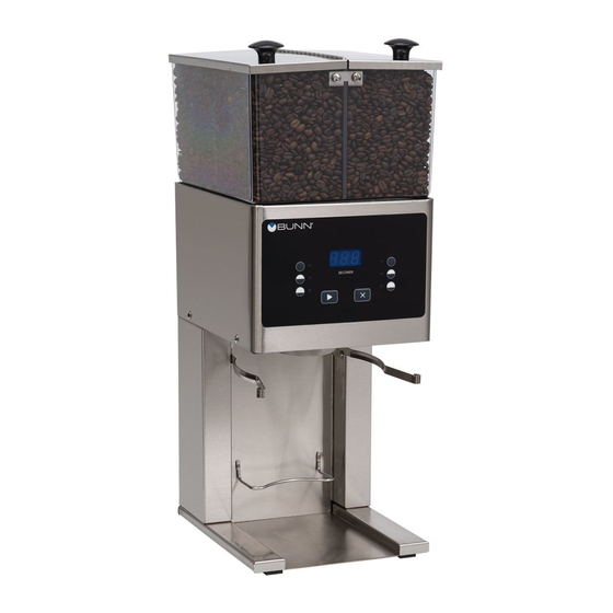
Bunn MHG Installation And Operating Manual
Mhg for use with smart funnel
Hide thumbs
Also See for MHG:
- Service & repair manual (79 pages) ,
- Installation & operation manual (14 pages) ,
- Specification (2 pages)
Advertisement
Table of Contents
Advertisement
Table of Contents

Related Manuals for Bunn MHG


Summary of Contents for Bunn MHG
- Page 1 Smart Funnel ® INSTALLATION AND OPERATING MANUAL BUNN-O-MATIC CORPORATION POST OFFICE BOX 3227 SPRINGFIELD, ILLINOIS 62708-3227 TELEPHONE: (217) 529-6601 FAX: (217) 529-6644 www.bunnomatic.com 36529.0000F 08/06 ©2004 Bunn-O-Matic Corporation...
-
Page 2: Table Of Contents
AS SPECIFIED HEREIN, TO REPAIR, REPLACEMENT OR REFUND. In no event shall BUNN be liable for any other damage or loss, including, but not limited to, lost profits, lost sales, loss of use of equipment, claims of Buyer’s customers, cost of capital, cost of down time, cost of substitute equipment facilities or services, or any other special, incidental or consequential damages. -
Page 3: User Notices
READ THE ENTIRE OPERATING MANUAL INCLUDING THE LIMIT OF WARRANTY AND LIABILITY BEFORE BUYING OR USING THIS PRODUCT 20545-0000D 01/04 © 1990 Bunn-O-Matic Corporation #20545.0000 ELECTRICAL REQUIREMENTS Refer to Data Plate on the Grinder, and local/national electrical codes to determine circuit requirements. -
Page 4: Initial Set-Up & Programming
The use of a damp cloth rinsed in any mild, non-abrasive, liquid detergent is recommended for cleaning all surfaces on Bunn-O-Matic equipment. Care should be taken not to scratch the hopper with any abrasive material. Regular cleaning will keep your grinder looking new for years. -
Page 5: Adjustments
ADJUSTMENTS The grind can be set from very fine to very coarse. The amount may be adjusted for use in most commercial coffee brewers. The following procedures should be used to make adjustments. A change in the burr adjustment will also change the amount dispensed. Any adjustment of the burrs should be followed by an adjustment of the timer. -
Page 6: Communicating Withcoffee Brewer
COMMUNICATING WITH COFFEE BREWER To Write A Name To A Hopper PRESS AND HOLD RIGHT HIDDEN BUTTON TO ENTER THE SET-UP MENUS NAME HOPPER? WHICH SIDE? LEFT DONE RIGHT REVIEW RECIPES Page 8 "COFFEE NAME" PRESSING EITHER "PREV" OR "NEXT" WILL SCROLL TO PREV SAVE NEXT ANOTHER COFFEE FLAVOR ARE YOU SURE? - Page 7 COMMUNICATING WITH COFFEE BREWER (Continued) Timer Adjustment (Control Board) Three different batch settings are selectable for each hopper. Each batch is independently adjustable by setting the length of time a slide gate opens to allow beans to drop into the grinding chamber. A second time setting for each batch determines how long the grind motor continues to run after the slide gate closes.
- Page 8 COMMUNICATING WITH COFFEE BREWER (Continued) To Review Or Change Grind Time PRESS AND HOLD RIGHT HIDDEN BUTTON TO ENTER THE SET-UP MENUS NAME HOPPER? PRESSING THE RIGHT HIDDEN REVIEW RECIPES? BUTTON THREE TIMES IN THIS MENU WILL TAKE YOU TO THE "SERVICE TOOLS" MENU GRIND TIME "#.#"...
- Page 9 COMMUNICATING WITH COFFEE BREWER (Continued) To Restore Factory Defaults Or Test Outputs and Switches TEST OUTPUTS? PRESS AND HOLD RIGHT HIDDEN BUTTON TO ENTER THE SET-UP MENUS NAME HOPPER? LEFT GATE NEXT REVIEW RECIPES? RIGHT GATE NEXT ENTER ASSET # AN000000 GRIND MOTOR NEXT...
- Page 10 COMMUNICATING WITH COFFEE BREWER (Continued) Resetting The Grinder Memory (To Match Chart Below) 1. Unplug grinder from the outlet. 2. Press in and hold both the buttons and plug cordset into the outlet. After a short pause, the display will show four rows of dashes. 3.
- Page 11 COMMUNICATING WITH COFFEE BREWER (Continued) Entering A Coffee Name Using A Recipe Card Press the STOP button and place the chip portion of the card under the sensor coil on the front of the grinder. The LCD display will enter the RECIPE CARD menu. CARD CONTAINS RECIPE FOR THE COFFEE NAME CAN BE...
-
Page 12: Wiring Diagram
SCHEMATIC WIRING DIAGRAM MHG P1, P2, P3 & P4 ARE PINS OF A POLARIZED FOUR-PIN CONNECTOR LIMIT RIGHT GATE THERMOSTAT WHI/YEL WHI/YEL J5-1 WHI/GRN LIMIT LEFT GATE THERMOSTAT WHI/ORN WHI/ORN CONTROL PC BOARD RELAY COIL J5-5 RIGHT HOPPER SENSOR J12-1 LEFT HOPPER SENSOR GRINDER MOTOR WHI/BLU...