Advertisement
Quick Links
Download this manual
See also:
Operating Manual
SDR24/96 Quick-Start Guide
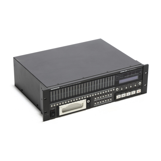
24 TRACK/24 BIT DIGITAL AUDIO RECORDER
1
2
3
4
5
6
7
8
POWER
Getting Started
Project
• Start a new project (PROJECT:New). Either accept
the default name (Project#1) by selecting New, or press
Page Right
to enter a new name. When finished,
press Page Left
and select New.
I/O
• Choose either the analog inputs or digital inputs using
the INPUT TYPE SELECT menu (SETUP:I/O:Page
Right Twice
:INPUT TYPE SELECT), or customize
a combination of both.
See "Hookups" on page 12 of the Operation Manual for
examples of both analog and digital connections.
• By default, track numbers are assigned to their
corresponding inputs and outputs. You can customize
the mapping of the inputs (SETUP:I/O:TRACK INPUT
SELECT) and outputs (SETUP:I/O:Page Right
TRACK OUTPUT SELECT) to different tracks.
Sync:
• Choose the sample clock source (SETUP:Sync:SClk).
If the SDR24/96 is providing the master clock, select
Internal. If the SDR is a slave and syncing to an
external clock through the Word Clock input, select
Word Clock. Select ADAT A, B, or C if syncing to a self-
clocking ADAT™ optical input.
• Choose the sample rate (SETUP:Sync:SRate). When
recording with the analog inputs, choose any sample
rate appropriate for your project. You must use the same
sample rate throughout a project. When recording with
the digital inputs, the sample rate must be the same as
the digital source.
• Choose your preferred sample size (SETUP:Sync:Page
Right
:SSize), either 16-bit or 24-bit.
• Choose the time code source (SETUP:Sync:TcSrc) if
the SDR is chasing to time code (T-CODE CHASE). Use
Jam Continuous when all devices are synced to the
same master clock. Use Chase when the you are using
the SDR24/96's internal sample clock (no external clock
connected) and you want to sync to external time code.
9
10
11
12
13
14
15
16
17
18
19
DELETE
TRACK
PROJECT
LAST
LOCATE
STORE
LOOP
Front Panel Description
at the inputs or outputs, depending on the monitoring
mode selected. OL on the meter corresponds to +22 dBu
at the analog input, and 0 dBFS at the digital input.
recording, or to select tracks for editing. The red LED at
the bottom of the meter blinks while in Record Standby,
and lights steadily while actually recording.
Media M•90 and the Project ORB™ cartridge.
be the last action in the History List). You cannot undo
Delete Last.
Virtual Tracks, and Track Name.
:
Open, Save, Save As, Delete, Copy, Rename, and Purge.
Delete, Cut, Copy, Paste, Place, Undo, and Redo.
SDR
ERROR
44.1k
48k
X2
TC
VARI
16 BIT
24 BIT
HOURS
P R O J E C T : F e e l t h e L o v e
A V A I L : 0 2 : 2 7 : 2 6 o n E X T
20
21
22
23
24
SELECT
SELECT
AUTO
T-CODE
REWIND
FAST FWD
EDIT
SETUP
TAKE
CHASE
ALL
AUTO
PUNCH
REHRSE
INPUT
INPUT
Channel Level Indicators: Indicate the signal level
Record Ready Buttons: Used to arm tracks for
POWER Switch: Turns the SDR24/96 on and off.
Drive Bay: For removable drives like the Mackie
DELETE LAST: Deletes the last record pass (must
TRACK: Accesses track options including Mute,
PROJECT: Accesses project options including New,
EDIT: Accesses common editing functions such as
SETUP: Accesses the following options:
• Record Options
♦
Record Safe
♦
Preroll before Locator
♦
Preroll
♦
Postroll
• I/O Options
Track Input Select
♦
Track Output Select
♦
• Sync Options
♦
Sample Clock
♦
Sample Rate
♦
Time Code Source
Frame Rate
♦
• Transport Options
Locate 1-4
♦
Current Locator Position
♦
♦
Transport Offset
• Disk Options
♦
Mount Drive
♦
Format Drive
• System Options
♦
USB Mass Storage Mode
SDR Footswitch
♦
♦
Remote Footswitch
96
HIGH RESOLUTION
NON-LINEAR RECORDER
EXT
CLOCK
MINUTES
SECONDS
FRAMES
SELECT
SELECT
STOP
PLAY
RECORD
♦
Locator Mode
♦
Auto Take Mode
♦
One Button Record
Input Type Select
♦
♦
Sample Size
♦
LTC Out
♦
MTC Out
VariSpeed
♦
Relative Offset
♦
Relative Mode
♦
♦
Auto Play
♦
Defragment Drive
♦
System Load
Date
♦
♦
Time
♦
About
Advertisement

Related Manuals for Mackie SDR24/96


Summary of Contents for Mackie SDR24/96
-
Page 1: Getting Started
POWER Switch: Turns the SDR24/96 on and off. Right Twice :INPUT TYPE SELECT), or customize Drive Bay: For removable drives like the Mackie a combination of both. Media M•90 and the Project ORB™ cartridge. See “Hookups” on page 12 of the Operation Manual for DELETE LAST: Deletes the last record pass (must examples of both analog and digital connections. -
Page 2: Rear Panel Features
50/60Hz RISQUE DE CHOC ELECTRIQUE — NE PAS OUVRIR CONCEIVED, DESIGNED, AND MANUFACTURED BY MACKIE DESIGNS INC • WOODINVILLE • WA 98072 • USA REPLACE WITH THE SAME TYPE FUSE AND RATING. UTILISE UN FUSIBLE DE RECHANGE DE MÊME TYPE.