Table of Contents
Advertisement
Copyright
This publication, including all photographs, illustrations and software, is protected
under international copyright laws, with all rights reserved. Neither this manual, nor
any of the material contained herein, may be reproduced without written consent of
the author.
Version 8.0
Disclaimer
The information in this document is subject to change without notice. The manufac-
turer makes no representations or warranties with respect to the contents hereof and
specifically disclaims any implied warranties of merchantability or fitness for any
particular purpose. The manufacturer reserves the right to revise this publication and
to make changes from time to time in the content hereof without obligation of the
manufacturer to notify any person of such revision or changes.
Trademark Recognition
Microsoft, MS-DOS and Windows are registered trademarks of Microsoft Corp.
AMD, Phenom, Athlon, Sempron and Duron are registered trademarks of AMD
Corporation.
Other product names used in this manual are the properties of their respective
owners and are acknowledged.
Federal Communications Commission (FCC)
This equipment has been tested and found to comply with the limits for a Class B
digital device, pursuant to Part 15 of the FCC Rules. These limits are designed to
provide reasonable protection against harmful interference in a residential installa-
tion. This equipment generates, uses, and can radiate radio frequency energy and, if
not installed and used in accordance with the instructions, may cause harmful inter-
ference to radio communications. However, there is no guarantee that interference
will not occur in a particular installation. If this equipment does cause harmful
interference to radio or television reception, which can be determined by turning the
equipment off and on, the user is encouraged to try to correct the interference by one
or more of the following measures:
•
Reorient or relocate the receiving antenna.
•
Increase the separation between the equipment and the receiver.
•
Connect the equipment onto an outlet on a circuit different from that to
which the receiver is connected.
•
Consult the dealer or an experienced radio/TV technician for help.
Shielded interconnect cables and a shielded AC power cable must be employed with
this equipment to ensure compliance with the pertinent RF emission limits govern-
ing this device. Changes or modifications not expressly approved by the system's
manufacturer could void the user's authority to operate the equipment.
Preface
Preface
Advertisement
Table of Contents

Related Manuals for ECS A740GM-M


Summary of Contents for ECS A740GM-M
- Page 1 Preface Copyright This publication, including all photographs, illustrations and software, is protected under international copyright laws, with all rights reserved. Neither this manual, nor any of the material contained herein, may be reproduced without written consent of the author. Version 8.0 Disclaimer The information in this document is subject to change without notice.
-
Page 2: Declaration Of Conformity
Declaration of Conformity This device complies with part 15 of the FCC rules. Operation is subject to the following conditions: • This device may not cause harmful interference, and • This device must accept any interference received, including interfer- ence that may cause undesired operation. Canadian Department of Communications This class B digital apparatus meets all requirements of the Canadian Interference- causing Equipment Regulations. -
Page 3: Table Of Contents
T T T T T ABLE OF CONTENTS ABLE OF CONTENTS ABLE OF CONTENTS ABLE OF CONTENTS ABLE OF CONTENTS Preface Chapter 1 Introducing the Motherboard Introduction....................1 Features....................2 Motherboard Components..............4 Chapter 2 7 7 7 7 7 Installing the Motherboard Safety Precautions................7 Choosing a Computer Case...............7 Installing the Motherboard in a Case..........7... - Page 4 Integrated Peripherals..............34 Power Management Setup.............35 PCI/PnP Configurations...............37 PC Health Status................38 Frequency/Voltage Control............40 Load Default Settings..............41 Supervisor Password..............41 User Password................42 Save & Exit Setup .................42 Exit Without Saving...............42 Updating the BIOS.................43 45 45 45 45 Chapter 4 Using the Motherboard Software About the Software DVD-ROM/CD-ROM........45 Auto-installing under Windows Vista/7...........45 Running Setup................46...
-
Page 5: Introducing The Motherboard
Chapter 1 Introducing the Motherboard Introduction Thank you for choosing the A740GM-M motherboard. This motherboard is a high performance, enhanced function motherboard that supports AMD Phenom II pro- cessor (socket AM2+)/Phenom /Athlon II/Athlon /Sempron processors for high-end business or personal desktop markets. The motherboard incorporates the AMD 740G (RS740) Northbridge (NB) and SB710 Southbridge (SB) chipsets. -
Page 6: Features
Feature Processor This motherboard uses a Socket AM2+ that carries the following features: • Accommodates AMD Phenom II processor (socket AM2+)/Phenom Athlon II/Athlon /Sempron processors • Supports HyperTransport (HT) 1.0 interface speeds HyperTransport Technology is a point-to-point link between two devices, it enables integrated circuits to exchange information at much higher speeds than currently available interconnect technologies. - Page 7 Audio (Optional) The onboard Audio provides the following features: • 5.1 Channel High Definition Audio Codec • DACs Support 96K/48K/44.1KHz DAC sample rate • Power support: Digital:3.3V; Analog:5.0V • and Tru Surround from SRS • Provides single ended CD input with DRM solutions and legacy OS issues •...
-
Page 8: Bios Firmware
BIOS Firmware The motherboard uses AMI BIOS that enables users to configure many system features including the following: • Power management • Wake-up alarms • CPU parameters • CPU and memory timing The firmware can also be used to set parameters for different processor clock speeds. -
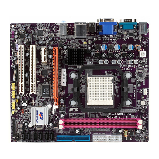
Page 9: Motherboard Components
Motherboard Components Introducing the Motherboard... - Page 10 Table of Motherboard Components LABEL COMPONENTS AMD Phenom II processor (socket AM2+)/ 1. CPU Socket Phenom /Athlon II/Athlon Sempron™ processors CPU cooling fan connector 2. CPU_FAN System cooling fan connector 3. SYS_FAN 4. DDR2_1~2 240-pin DDR2 SDRAM slots Standard 24-pin ATX power connector 5.
-
Page 11: Installing The Motherboard
Chapter 2 Installing the Motherboard Safety Precautions • Follow these safety precautions when installing the motherboard • Wear a grounding strap attached to a grounded device to avoid dam- age from static electricity • Discharge static electricity by touching the metal case of a safely grounded object before working on the motherboard •... -
Page 12: Checking Jumper Settings
Do not over-tighten the screws as this can stress the motherboard. Checking Jumper Settings This section explains how to set jumpers for correct configuration of the motherboard. Setting Jumpers Use the motherboard jumpers to set system configuration options. Jumpers with more than one pin are numbered. -
Page 13: Checking Jumper Settings
Checking Jumper Settings The following illustration shows the location of the motherboard jumpers. Pin 1 is labeled. Jumper Settings Setting (default) Jumper Type Description 1-2: NORMAL 2-3: CLEAR CMOS CLR_CMOS 3-pin Clear CMOS Before clearing the CLR_CMOS CMOS, make sure to turn off the system. -
Page 14: Installing Hardware
Installing Hardware Installing the Processor Caution: When installing a CPU heatsink and cooling fan make sure that you DO NOT scratch the motherboard or any of the surface- mount resistors with the clip of the cooling fan. If the clip of the cooling fan scrapes across the motherboard, you may cause serious damage to the motherboard or its components. -
Page 15: Cpu Installation Procedure
CPU Installation Procedure The following illustration shows CPU installation components. Install your CPU. Pull up the lever away from the socket and lift up to 90-degree angle. Locate the CPU cut edge (the corner with the pin hold noticeably missing). Align and insert the CPU correctly. -
Page 16: Installing Memory Modules
Installing Memory Modules This motherboard accommodates two memory modules. It can support two 240-pin DDR2 800/667/533/400. The total memory capacity is 8 GB. DDR2 SDRAM memory module table Memory module Memory Bus DDR2 200 MHz DDR2 266 MHz DDR2 333 MHz DDR2 400 MHz You must install at least one module in any of the two slots. - Page 17 Table A: DDR2 (memory module) QVL (Qualified Vendor List) The following DDR2 800/667/533/400 memory modules have been tested and quali- fied for use with this motherboard. Type Size Vendor Module Name Hynix HYMP532U646-E3 AA DDR2 400 256 MB Nanya NT512T64U88A0F-5A 512 MB Elixir M2U25664TUH4A0F-37B...
- Page 18 Type Size Vendor Module Name Infineon HYS64T32000HU-25F-B 256MB A-DATA M2OAD6G3H3160I1E53 Aeneon AET660UD00-25DB98X 512MB Apacer AU512E800C5KBGC DDR2 800 APOGEE AU51082-800P505 Infineon HYS64T64000HU-25F-B Kingston KHX6400D2ULK2/1G Nanya NT512T64U88BOBY-25C AL6E8E63H-8E1 APOGEE AU1G082-800P000 Infineon HYS64T128020HU-25F-8 Kingston KHX6400D2ULK2/2G Nanya NT1GT64U8HBOBY-25C AL7E8E63H-8E1 UMAX 53016042-7100B Installing the Motherboard...
-
Page 19: Expansion Slots
Expansion Slots Installing Add-on Cards The slots on this motherboard are designed to hold expansion cards and connect them to the system bus. Expansion slots are a means of adding or enhancing the motherboard’s features and capabilities. With these efficient facilities, you can in- crease the motherboard’s capabilities by adding hardware that performs tasks that are not part of the basic system. - Page 20 Follow these instructions to install an add-on card: Remove a blanking plate from the system case corresponding to the slot you are going to use. Install the edge connector of the add-on card into the expansion slot. Ensure that the edge connector is correctly seated in the slot. Secure the metal bracket of the card to the system case with a screw.
-
Page 21: Connecting Optional Devices
Connecting Optional Devices Refer to the following for information on connecting the motherboard’s optional devices: F_USB1~3: Front Panel USB headers The motherboard has four USB ports installed on the rear edge I/O port array. Additionally, some computer cases have USB ports at the front of the case. If you have this kind of case, use auxiliary USB connector to connect the front-mounted ports to the motherboard. - Page 22 LPT: Onboard parallel port header This is a header that can ba used to connect to the printer, scanner or other devices. Pin Signal Name Signal Name STROBE ERROR INIT SLCTIN Ground Ground Ground Ground Ground Ground Ground BUSK Ground SLCT F_AUDIO: Front Panel Audio header This header allows the user to install auxiliary front-oriented microphone and line-...
- Page 23 CD_IN: Analog audio input connector Signal Name Function CD_L Left CD-in signal Ground Ground CD_R Right CD-in signal SPDIFO: SPDIF out header This is an optional header that provides an S/PDIF (Sony/Philips Digital Interface) output to digital multimedia device through optical fiber or coaxial connector. Signal Name Function SPDIF...
-
Page 24: Installing A Hard Disk Drive/Cd-Rom/Sata Hard Drive
Installing a Hard Disk Drive/CD-ROM/SATA Hard Drive This section describes how to install IDE devices such as a hard disk drive and a CD- ROM drive. About IDE Devices Your motherboard has one IDE interface. IDE: IDE Connector This motherboard supports six high data transfer SATA ports with each runs up to 3.0 Gb/s. - Page 25 Refer to the illustration below for proper installation: Attach either cable end to the connector on the motherboard. Attach the other cable end to the SATA hard drive. Attach the SATA power cable to the SATA hard drive and connect the other end to the power supply.
-
Page 26: Connecting I/O Devices
Connecting I/O Devices The backplane of the motherboard has the following I/O ports: PS2 Mouse Use the upper PS/2 port to connect a PS/2 pointing device. PS2 Keyboard Use the lower PS/2 port to connect a PS/2 keyboard. Serial Port Use the COM port to connect serial devices such as mice or (COM1) fax/modems. -
Page 27: Connecting Case Components
Connecting Case Components After you have installed the motherboard into a case, you can begin connecting the motherboard components. Refer to the following: Connect the CPU cooling fan cable to CPU_FAN. Connect the standard power supply connector to ATX_POWER. Connect the case speaker cable to SPK. Connect the case switches and indicator LEDs to the F_PANEL. -
Page 28: Atx 12V Power Connector
CPU_FAN: Cooling FAN Power Connector Function Signal Name System Ground +12V Power +12V Sense Sensor CPU FAN control Users please note that the fan connector supports the CPU cooling fan of 1.1A~2.2A (26.4W max.) at +12V. ATX_POWER: ATX 24-pin Power Connector Signal Name Signal Name +3.3V... -
Page 29: Front Panel Header
Front Panel Header The front panel header (F_PANEL) provides a standard set of switch and LED headers commonly found on ATX or Micro ATX cases. Refer to the table below for information: Signal Function Signal Function HD_LED_P Hard disk LED (+) 2 FP PWR/SLP *MSG LED (+) HD_LED_N Hard disk LED (-) FP PWR/SLP *MSG LED (-) - Page 30 Memo Installing the Motherboard...
-
Page 31: Using Bios
Chapter 3 Using BIOS About the Setup Utility The computer uses the latest “American Megatrends Inc. ” BIOS with support for Windows Plug and Play. The CMOS chip on the motherboard contains the ROM setup instructions for configuring the motherboard BIOS. The BIOS (Basic Input and Output System) Setup Utility displays the system’s configuration status and provides you with options to set system parameters. -
Page 32: Resetting The Default Cmos Values
Press the delete key to access the BIOS Setup Utility. CMOS Setup Utility -- Copyright (C) 1985-2007, American Megatrends, Inc. Standard CMOS Setup Frequency/Voltage Control Advanced Setup Load Default Settings Advanced Chipset Setup Supervisor Password Integrated Peripherals User Password Power Management Setup Save &... -
Page 33: Using Bios
Using BIOS When you start the Setup Utility, the main menu appears. The main menu of the Setup Utility displays a list of the options that are available. A highlight indicates which option is currently selected. Use the cursor arrow keys to move the highlight to other options. -
Page 34: Standard Cmos Setup
For the purpose of better product maintenance, the manufacture reserves the right to change the BIOS items presented in this manual. The BIOS setup screens shown in this chapter are for reference only and may differ from the actual BIOS. Please visit the manufacture’s website for updated manual. - Page 35 LBA/Large Mode (Auto) Use this item to set the LAB/Large mode to enhance hard disk performance by optimizing the area the hard disk is visited each time. Block (Multi-Sector Transfer) (Auto) If the feature is enabled, it will enhance hard disk performance by reading or writing more data during each transfer.
-
Page 36: Advanced Setup
Advanced Setup This page sets up more advanced information about your system. Handle this page with caution. Any changes can affect the operation of your computer. CMOS Setup Utility - Copyright (C) 1985-2007, American Megatrends, Inc. Advanced Setup HT Frequency Auto Help Item AMD C&Q... -
Page 37: Advanced Chipset Setup
Boot Other Device (Yes) When enabled, the system searches all other possible locations for an operating system if it fails to find one in the devices specified under the First, Second and Third boot devices. Press <Esc> to return to the main menu setting page. Advanced Chipset Setup This page sets up more advanced information about your system. -
Page 38: Integrated Peripherals
Integrated Peripherals This page sets up some parameters for peripheral devices connected to the system. CMOS Setup Utility - Copyright (C) 1985-2007, American Megatrends, Inc. Integrated Peripherals Onboard IDE Controller Enabled Help Item SATA Configuration Enanled Onboard SATA Mode Options Onboard AUDIO Function Enabled Onboard LAN Function... -
Page 39: Power Management Setup
Parallel Port Mode (ECP) Use this item to select the parallel port mode. You can select Normal (Standard Parallel Port), ECP (Extended Capabilities Port), EPP (Enhanced Parallel Port), or BPP (Bi-Directional Parallel Port). ECP Mode DMA Channel (DMA3) Use this item to assign a DMA channel to the parallel port. Parallel Port IRQ (IRQ7) Use this item to assign IRQ to the parallel port. - Page 40 Soft-off by PWR-BTTN (Instant off) Under ACPI (Advanced Configuration and Power management Interface) you can create a software power down. In a software power down, the system can be resumed by Wake Up Alarms. This item lets you install a software power down that is con- trolled by the power button on your system.
-
Page 41: Pci/Pnp Configurations
PCI / PnP Configuration This page sets up some parameters for devices installed on the PCI bus and those utilizing the system plug and play capability. CMOS Setup Utility - Copyright (C) 1985-2007, American Megatrends, Inc. PCI / PnP Setup Help Item Allocate IRQ to PCI VGA Init Display First... -
Page 42: Pc Health Status
PC Health Status On motherboards support hardware monitoring, this item lets you monitor the parameters for critical voltages, temperatures and fan speeds. CMOS Setup Utility - Copyright (C) 1985-2007, American Megatrends, Inc. PC Health Status Help Item -=- System Hardware Monitor-=- Smart Fan Function Press Enter Shutdown Temperature... - Page 43 DeltaT (+3) This item specifies the range that controls CPU temperature and keeps it from going so high or so low when smart fan works. SMART Fan Slope PWM value (5 PWM value/°C) This item is used to set the Slope Select PWM of the smart fan. Press <Esc>...
-
Page 44: Frequency/Voltage Control
Frequency/Voltage Control This page enables you to set the clock speed and system bus for your system. The clock speed and system bus are determined by the kind of processor you have in- stalled in your system. CMOS Setup Utility - Copyright (C) 1985-2007, American Megatrends, Inc. Frequency/Voltage Control Help item Auto Detect DIMM/PCI CIK... -
Page 45: Load Default Settings
Load Default Settings This option opens a dialog box to ask if you are sure to install optimized defaults or not. You select [OK], and then press <Enter>, the Setup Utility loads all default values; or select [Cancel], and then press <Enter>, the Setup Utility does not load default values. -
Page 46: User Password
User Password This page helps you install or change a password. CMOS Setup Utility - Copyright (C) 1985-2007, American Megatrends, Inc. User Password User Password : Not Installed Help item Change User Password Press Enter Install or Change the password. : Move Enter : Select +/-/: Value... -
Page 47: Updating The Bios
Updating the BIOS You can download and install updated BIOS for this motherboard from the manufacturer’s Web site. New BIOS provides support for new peripherals, improve- ments in performance, or fixes for known bugs. Install new BIOS as follows: If your motherboard has a BIOS protection jumper, change the setting to allow BIOS flashing. - Page 48 Memo Using BIOS...
-
Page 49: Using The Motherboard Software
Chapter 4 Using the Motherboard Software About the Software DVD-ROM/CD-ROM The support software DVD-ROM/CD-ROM that is included in the motherboard package contains all the drivers and utility programs needed to properly run the bundled products. Below you can find a brief description of each software program, and the location for your motherboard version. -
Page 50: Running Setup
Drivers Tab Setup Click the Setup button to run the software installation program. Select from the menu which software you want to install. Browse CD The Browse CD button is the standard Windows command that al- lows you to open Windows Explorer and show the contents of the support disk. - Page 51 Click Next. The following screen appears: Check the box next to the items you want to install. The default options are recom- mended. Click Next run the Installation Wizard. An item installation screen appears: Follow the instructions on the screen to install the items. Drivers and software are automatically installed in sequence.
-
Page 52: Manual Installation
Windows Vista/7 will appear below UAC (User Account Control) message after the system restart. You must select “Allow” to install the next driver. Continue this process to complete the drivers installation. Manual Installation Insert the disk in the DVD-ROM/CD-ROM drive and locate the PATH.DOC file in the root directory. -
Page 53: Setting Up Amd Sb710 Raid Configuration
Chapter 5 Setting Up AMD SB710 RAID Configuration Setting Up a bootable RAID Array This section explains how to configure a bootable AMD RAID array. Setting Up the BIOS Start your computer, then press Delete to enter the BIOS setup. The BIOS CMOS Setup Utility screen appears. - Page 54 Press F10 to save the configuration and exit. The PC reboots. Enter the RAID BIOS Setup by pressing Ctrl-F when prompted, and proceed to set up the AMD RAID BIOS as described in the next section. Configuring the AMD RAID BIOS The AMD RAID BIOS set up lets you choose the RAID type and which hard drives you want to make part of the array.
- Page 55 Select [2], then select LD 1 in the following page. The Define LD Menu screen appears (Figure 1.4). Figure 1.4 Define LD Menu Using the Define a New Array Screen If necessary, press the tab key to move from field to field until the appropriate field is highlighted.
- Page 56 Assigning the Disks 1. Select the Assignment to Y to designate a free disk to be used as a RAID array disk. Figure 1.5 illustrates the Define a New Array screen after two disks have been assigned as RAID 0 array disks. Figure 1.5 FastBuild Utility—Array Disks Assigned 2.
- Page 57 Press ESC to exit. The Main Menu screen appears (Figure 1.7). Figure 1.7 Main Menu Press Y to reboot. The following screen appears (Figure 1.8). Figure 1.8 AMD RAID Configuration...
- Page 58 Installing the RAID Drivers Your system may come with a Windows install CD that already includes AMD RAID drivers. If so, then this section is not relevant. If that is not the case (or you are trying to install a new version of Windows), then you will need an AMD RAID driver F6 install floppy.
- Page 59 The following Windows Setup screen appears: Figure 1.11 Windows Setup—Selected SCSI Adapter Select “ATI AHCI Compatible RAID Controller-x86 platform” and press Enter for 32-bit OS or Select “ATI AHCI Compatible RAID Controller-x64 platform” and press Enter for 64-bit OS. The following Windows Setup screen appears listing both drivers:. Figure 1.12 Windows Setup—AMD drives listed Press Enter to continue with Windows XP Installation.
- Page 60 Memo AMD RAID Configuration...
-
Page 61: Trouble Shooting
Chapter 6 Trouble Shooting Start up problems during assembly After assembling the PC for the first time you may experience some start up problems. Before calling for technical support or returning for warranty, this chapter may help to address some of the common questions using some basic troubleshooting tips. -
Page 62: Start Up Problems After Prolong Use
c) The PC suddenly shuts down while booting up. 1. The CPU may experience overheating so it will shutdown to protect itself. Ensure the CPU fan is working properly. 2. From the BIOS setting, try to disable the Smartfan function to let the fan run at default speed. - Page 64 Memo Trouble Shooting...