Table of Contents
Advertisement
Advertisement
Table of Contents

Related Manuals for ECS A780GM-A Ultra


Summary of Contents for ECS A780GM-A Ultra
- Page 3 Preface Copyright This publication, including all photographs, illustrations and software, is protected under international copyright laws, with all rights reserved. Neither this manual, nor any of the material contained herein, may be reproduced without written consent of the author. Version 1.0 Disclaimer The information in this document is subject to change without notice.
-
Page 4: Declaration Of Conformity
Declaration of Conformity This device complies with part 15 of the FCC rules. Operation is subject to the following conditions: • This device may not cause harmful interference, and • This device must accept any interference received, including interfer- ence that may cause undesired operation. Canadian Department of Communications This class B digital apparatus meets all requirements of the Canadian Interference- causing Equipment Regulations. -
Page 5: Table Of Contents
T T T T T ABLE OF CONTENTS ABLE OF CONTENTS ABLE OF CONTENTS ABLE OF CONTENTS ABLE OF CONTENTS Preface Chapter 1 Introducing the Motherboard Introduction....................1 Features....................2 Motherboard Components..............4 Chapter 2 7 7 7 7 7 Installing the Motherboard Safety Precautions................7 Choosing a Computer Case..............7 Installing the Motherboard in a Case.. - Page 6 Integrated Peripherals..............35 Power Management Setup.............36 PCI/PnP Setup................37 PC Health Status................38 M.I.B (MB Intelligent Bios)............40 Load Default Settings..............42 Supervisor Password..............42 User Password................43 Save & Exit Setup .................43 Exit Without Saving...............43 Updating the BIOS.................44 Chapter 4 45 45 45 45 Using the Motherboard Software About the Software CD-ROM............45 Auto-installing under Windows XP/Vista........45 Running Setup................46...
-
Page 7: Introducing The Motherboard
Chapter 1 Introducing the Motherboard Introduction Thank you for choosing the A780GM-A Ultra motherboard. This motherboard is a high performance, enhanced function motherboard that supports socket for Phenom processor (socket AM2+)/Athlon 64 X2 Dual-Core/Athlon Sempron processors for high-end business or personal desktop markets. -
Page 8: Features
Feature Processor This motherboard uses a socket AM2+/AM2 that carries the following features: • Accommodates AMD Phenom processor (socket AM2+) AMD Athlon 64 X2 Dual-Core/Athlon 64/Sempron™ processors • Supports HyperTransport (HT) 3.0 interface speeds HyperTransport Technology is a point-to-point link between two devices, it enables integrated circuits to exchange information at much higher speeds than currently available interconnect technologies. -
Page 9: Onboard Lan
Audio • All DACs support 192K/96K/48K/44.1KHz DAC sample rate • High-quality analog differential CD input • Software selectable 2.5V/3.75V VREFOUT • Meets Microsoft WLP 3.08 audio requirements • Direct Sound 3D compatible Onboard LAN • Supports PCI Express • Integrated 10/100/1000 transceiver •... -
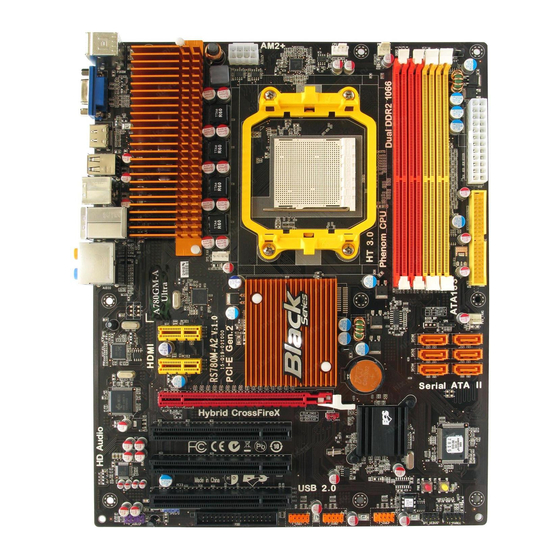
Page 10: Motherboard Components
Motherboard Components Introducing the Motherboard... - Page 11 Table of Motherboard Components LABEL COMPONENTS Socket for AMD Phenom processor (socket AM2+)/ 1. CPU Socket Athlon 64 X2 Dual-Core/Athlon 64/Sempron processors 2. CPU_FAN CPU cooling fan connector 3. PWR_FAN2 Power cooling fan connector 4. DDR2_1~4 240-pin DDR2 SDRAM slots 5.
- Page 12 Memo Introducing the Motherboard...
-
Page 13: Installing The Motherboard
Chapter 2 Installing the Motherboard Safety Precautions • Follow these safety precautions when installing the motherboard • Wear a grounding strap attached to a grounded device to avoid dam- age from static electricity • Discharge static electricity by touching the metal case of a safely grounded object before working on the motherboard •... -
Page 14: Checking Jumper Settings
Do not over-tighten the screws as this can stress the motherboard. Checking Jumper Settings This section explains how to set jumpers for correct configuration of the motherboard. Setting Jumpers Use the motherboard jumpers to set system configuration options. Jumpers with more than one pin are numbered. -
Page 15: Checking Jumper Settings
Checking Jumper Settings The following illustration shows the location of the motherboard jumpers. Pin 1 is labeled. Jumper Settings Jumper Type Description Setting (default) 1-2: NORMAL 2-3: CLEAR CLR_CMOS 3-pin Clear CMOS Before clearing the CLR_CMOS CMOS, make sure to turn off the system. -
Page 16: Installing Hardware
Installing Hardware Installing the Processor Caution: When installing a CPU heatsink and cooling fan make sure that you DO NOT scratch the motherboard or any of the surface- mount resistors with the clip of the cooling fan. If the clip of the cooling fan scrapes across the motherboard, you may cause serious damage to the motherboard or its components. -
Page 17: Installing Memory Modules
CPU Installation Procedure The following illustration shows CPU installation components. Install your CPU. Pull up the lever away from the socket and lift up to 90-degree angle. Locate the CPU cut edge (the corner with the pin hold noticeably missing). Align and insert the CPU correctly. -
Page 18: Installation Procedure
Installation Procedure Refer to the following to install the memory modules. This motherboard supports unbuffered DDR2 SDRAM only. Push the latches on each side of the DIMM slot down. Align the memory module with the slot. The DIMM slots are keyed with notches and the DIMMs are keyed with cutouts so that they can only be installed correctly. - Page 19 Table A: DDR2 (memory module) QVL (Qualified Vendor List) The following DDR2 1066 (AM2+)/800/667 memory modules have been tested and qualified for use with this motherboard. Type Size Vendor Module Name Apacer 78.91G92.9K5 Micron MT 4HTF6464AY-667E1 512 MB AL6E8E63J-6E1 Ramxel R ML1520M38D6F-667 Samsung K4T 51083QC...
- Page 20 Infineon HYS64T 64020HU -2.5-A/Infineon/HYB18T256 800AF25 Kingston KVR800D2N5/512 512 MB Micron MT 8HTF6464AY-80ED4 H YS72T64000HU-2.5- Qimonda B/Qimonda/HYB18T 512800BF25 M2GVD6G3I41P0U 1E5E/A-DATA/VD29608A8D- A-DATA 25EG-E0722 AET760UD00-25DC 08X Aeneon AET760UD00-30DB97X/Aeneon/AET93R250B 0725 AU01GE800C5KBGC/Apacer/AM4B5708JQJS8E0749 Apacer 78.01GA0.9K5 Geil Geil Millenary/Geil/GL2L64M088BA18H Hexon ELPT7AU DR-25M48 1 GB KHX6400D2ULK2/2G Kingston KVR 800D2N5/1G R ML1320EH38D7F-800/Elpida/E5108AHSE-8E-E Ramaxel DDR2 800...
-
Page 21: Expansion Slots
Expansion Slots Installing Add-on Cards The slots on this motherboard are designed to hold expansion cards and connect them to the system bus. Expansion slots are a means of adding or enhancing the motherboard’s features and capabilities. With these efficient facilities, you can in- crease the motherboard’s capabilities by adding hardware that performs tasks that are not part of the basic system. - Page 22 Follow these instructions to install an add-on card: Remove a blanking plate from the system case corresponding to the slot you are going to use. Install the edge connector of the add-on card into the expansion slot. Ensure that the edge connector is correctly seated in the slot. Secure the metal bracket of the card to the system case with a screw.
-
Page 23: Connecting Optional Devices
Connecting Optional Devices Refer to the following for information on connecting the motherboard’s optional devices: Installing the Motherboard... -
Page 24: Connectors And Headers
SATA1~6: Serial ATA connectors These connectors are used to support the new Serial ATA devices for the highest data transfer rates (3.0 Gb/s), simpler disk drive cabling and easier PC assembly. It elimi- nates limitations of the current Parallel ATA interface. But maintains register com- patibility and software compatibility with Parallel ATA. - Page 25 F_USB1~3: Front Panel USB headers The motherboard has six USB ports installed on the rear edge I/O port array. Addi- tionally, some computer cases have USB ports at the front of the case. If you have this kind of case, use auxiliary USB connector to connect the front-mounted ports to the motherboard.
-
Page 26: Installing A Hard Disk Drive/Cd-Rom/Sata Hard Drive
Installing a Hard Disk Drive/CD-ROM/SATA Hard Drive This section describes how to install IDE devices such as a hard disk drive and a CD- ROM drive. About IDE Devices Your motherboard has one IDE interface. An IDE ribbon cable supporting two IDE devices is bundled with the motherboard. -
Page 27: Installing A Floppy Diskette Drive
Refer to the illustration below for proper installation: Attach either cable end to the connector on the motherboard. Attach the other cable end to the SATA hard drive. Attach the SATA power cable to the SATA hard drive and connect the other end to the power supply. -
Page 28: Connecting I/O Devices
Connecting I/O Devices The backplane of the motherboard has the following I/O ports: PS2 Mouse Use the upper PS/2 port to connect a PS/2 pointing device. PS2 Keyboard Use the lower PS/2 port to connect a PS/2 keyboard. VGA Port Connect your monitor to the VGA port. -
Page 29: Connecting Case Components
Connecting Case Components After you have installed the motherboard into a case, you can begin connecting the motherboard components. Refer to the following: Connect the CPU cooling fan cable to CPU_FAN. Connect the standard power supply connector to ATX_POWER. Connect the power cooling fan connector to PWR_FAN1/2. Connect the case speaker cable to SPK. - Page 30 CPU_FAN/SYS_FAN: FAN Power Connectors Function Signal Name System Ground +12V Power +12V Sense Sensor CPU FAN control Users please note that the fan connector supports the CPU cooling fan of 1.1A~2.2A (26.4W max.) at +12V. ATX_POWER: ATX 24-pin Power Connector Signal Name Signal Name +3.3V...
-
Page 31: Front Panel Header
Front Panel Header The front panel header (F_PANEL) provides a standard set of switch and LED headers commonly found on ATX or Micro ATX cases. Refer to the table below for information: Signal Function Signal Function HD_LED_P Hard disk LED (+) 2 FP PWR/SLP *MSG LED (+) HD_LED_N Hard disk LED (-) FP PWR/SLP *MSG LED (-) - Page 32 Memo Installing the Motherboard...
-
Page 33: Using Bios
Chapter 3 Using BIOS About the Setup Utility The computer uses the latest “American Megatrends Inc. ” BIOS with support for Windows Plug and Play. The CMOS chip on the motherboard contains the ROM setup instructions for configuring the motherboard BIOS. The BIOS (Basic Input and Output System) Setup Utility displays the system’s configuration status and provides you with options to set system parameters. -
Page 34: Using Bios
Press the delete key to access the BIOS Setup Utility. CMOS Setup Utility -- Copyright (C) 1985-2005, American Megatrends, Inc. Standard CMOS Setup M.I.B. (MB Intelligent Bios) Advanced Setup Load Default Settings Advanced Chipset Setup Supervisor Password Integrated Peripherals User Password Power Management Setup Save &... -
Page 35: Standard Cmos Setup
For the purpose of better product maintenance, the manufacture reserves the right to change the BIOS items presented in this manual. The BIOS setup screens shown in this chapter are for reference only and may differ from the actual BIOS. Please visit the manufacture’s website for updated manual. Standard CMOS Setup This option displays basic information about your system. - Page 36 IDE Master/Slave, SATA1~6 Your computer has one IDE channel which can be installed with one or two devices (Master and Slave). In addition, this motherboard supports six SATA channels and each channel allows one SATA device to be installed. Use these items to configure each device on the IDE channel.
- Page 37 IDE BusMaster (Enabled) This item enables or disables the DMA under DOS mode. We recommend you to leave this item at the default value. Drive A (1.44 MB 3 ”) This item defines the characteristics of any diskette drive attached to the system. You can connect one or two diskette drives.
-
Page 38: Advanced Setup
Advanced Setup This page sets up more advanced information about your system. Handle this page with caution. Any changes can affect the operation of your computer. CMOS Setup Utility - Copyright (C) 1985-2005, American Megatrends, Inc. Advanced Setup Help Item HT Frequency Auto CPU Virtualization... - Page 39 Removable Drives (Press Enter) Scroll to this item and press <Enter> to view the following screen: CMOS Setup Utility - Copyright (C) 1985-2005, American Megatrends, Inc. Removable Drives Help Item Removable Drives 1st Drive 1st FLOPPY DRIVE Specifies the boot sequence from the available devices.
-
Page 40: Advanced Chipset Setup
Advanced Chipset Setup This page sets up more advanced information about your system. Handle this page with caution. Any changes can affect the operation of your computer. CMOS Setup Utility - Copyright (C) 1985-2005, American Megatrends, Inc. Advanced Chipset Setup Help Item Internal Graphics Mode GFX Clock Override... -
Page 41: Integrated Peripherals
Integrated Peripherals This page sets up some parameters for peripheral devices connected to the system. CMOS Setup Utility - Copyright (C) 1985-2005, American Megatrends, Inc. Integrated Peripherals Help Item Onboard IDE Controller Enabled SATA Configuration DISABLED: disables the Onboard SATA Mode Enabled Onboard AUDIO Function Enabled... -
Page 42: Power Management Setup
Power Management Setup This page sets up some parameters for system power management operation. CMOS Setup Utility - Copyright (C) 1985-2005, American Megatrends, Inc. Power Management Setup Help Item ACPI Suspend Type Soft-off by PWR-BTTN Instant Off Select the ACPI PWRON After PWR-Fail Power Off state used for... -
Page 43: Pci/Pnp Setup
Resume By PS2 KB (S3) (Disabled) This item enables or disables you to allow keyboard activity to awaken the system from power saving mode. Resume By PS2 MS (S3) (Disabled) This item enables or disables you to allow mouse activity to awaken the system from power saving mode. -
Page 44: Pc Health Status
PC Health Status On motherboards support hardware monitoring, this item lets you monitor the parameters for critical voltages, temperatures and fan speeds. CMOS Setup Utility - Copyright (C) 1985-2005, American Megatrends, Inc. PC Health Status Help Item -=- System Hardware Monitor-=- Smart Fan Function Press Enter Shutdown Temperature... - Page 45 DeltaT1 (+3) This item specifies the range that controls CPU temperature and keeps it from going so high or so low when smart fan works. SMART Fan Slope PWM value (4 PWM value/°C) This item is used to set the Slope Select PWM of the smart fan. SMART Fan2 Control (Disabled) This item allows you to enable or disable the control of the system fan speed by changing the fan voltage.
-
Page 46: Mb Intelligent Bios)
: N/A, 3 CLK Row Cycle (Trc) : N/A, 24 CLK : Move Enter : Select +/-/: Value F10: Save ECS: Exit F1: General help F9: Optimized Defaults DRAM Frequency (Auto) This item enables users to adjust the DRAM frequency. The default setting is auto and we recommend users leave the setting unchanged. - Page 47 Bank Interleaving (Auto) This item is used to set the bank interleaving. Channel Interleaving (XOR of Address bits) This item is used to set the channel interleaving. Memory CLK (N/A, 400 MHz) This item is used to set the memory clock mode. CAS Latency (Tcl) (N/A, 5.0) This item controls the timing delay (inclockcycles) before the DRAM starts a read command after receiving it.
-
Page 48: Load Default Settings
Voltage Function (Disabled) Use this item to enable or disable the Voltage Function. If enable, users can increase the hardware voltage through BIOS settings. Warning: Please pay attention that doing overvoltage may result in dam- age to hardware. AMD Phenon (tm) 8550 Triple-Core Processor Speed (2200MHz) This is display-only field and displays the information of the CPU installed in your computer. -
Page 49: User Password
User Password This page helps you install or change a password. CMOS Setup Utility - Copyright (C) 1985-2005, American Megatrends, Inc. User Password Help Item User Password : Not Installed : Move Enter : Select +/-/: Value F10: Save ESC: Exit F1:General Help F9: Optimized Defaults User Password (Not Installed) -
Page 50: Updating The Bios
Updating the BIOS You can download and install updated BIOS for this motherboard from the manufacturer’s Web site. New BIOS provides support for new peripherals, improve- ments in performance, or fixes for known bugs. Install new BIOS as follows: If your motherboard has a BIOS protection jumper, change the setting to allow BIOS flashing. -
Page 51: Using The Motherboard Software
Chapter 4 Using the Motherboard Software About the Software CD-ROM The support software CD-ROM that is included in the motherboard package contains all the drivers and utility programs needed to properly run the bundled products. Below you can find a brief description of each software program, and the location for your motherboard version. -
Page 52: Running Setup
Setup Tab Setup Click the Setup button to run the software installation program. Browse CD The Browse CD button is the standard Windows command that allows you to open Windows Explorer and show the contents of the support CD. Before installing the software from Windows Explorer, look for a file named README.TXT, INSTALL.TXT or something similar. - Page 53 Click Next. The following screen appears: Check the box next to the items you want to install. The default options are recom mended. Click Next run the Installation Wizard. An item installation screen appears: Follow the instructions on the screen to install the items. 1.
- Page 54 Method 1. Run Reboot Setup Windows Vista will block startup programs by default when installing drivers after the system restart. You must select taskbar icon Run Blocked Program and run Reboot Setup to install the next driver, until you finish all drivers installation. Method 2.
- Page 55 Select Classic View. Set User Account. Select Turn User Account Control on or off and press Continue. Using the Motherboard Software...
-
Page 56: Manual Installation
These software(s) are subject to change at anytime without prior no tice. Please refer to the support CD for available software. Please go to ECS website to download AMD Cool “n” Quiet technology. Using the Motherboard Software... -
Page 57: Hdmi Audio Setting Sop
HDMI Audio setting SOP OS: XP system 1. Control Panel-->Sound and Audio Device Properties a. Audio--> Sound playback--> Default device--> HD Auido Output b. Audio--> Sound playback--> Default device--> HDMI Auido Output a. User Playback Audio speaker function working b. User Playback HDMI speaker function working Using the Motherboard Software... - Page 58 OS: Vista system Control Panel--> Soundback--> Sound--> Digital Output Device (HDMI) --> Set Default 1. Volume --> Playback 2. Digital Output Device (HDMI) --> Set Default --> OK User HDMI Playback function working Using the Motherboard Software...
- Page 59 3. Speaker --> Set Default --> OK User Speaker Palyback function working 4. SPDIF-Out --> Set Default --> OK User SPDIF-Out Playback function working This concludes chapter 4. Using the Motherboard Software...
- Page 60 Memo Using the Motherboard Software...
-
Page 61: Hybrid Graphics ® Technology Support
Chapter 5 Hybrid Graphics Technology Support ® ® Hybrid Graphics Technology The Hybrid Graphics ® technology provides significant display performance boost to AMD-based systems by inserting the external PCI Express graphics card and enabling both the discrete GPU and the RS780 graphics core to render simultaneously in Hybrid CrossFire mode. - Page 62 SurroundView provides the power and convenience of multiadapter, multimonitor support for computers that use a PCI-Express based graphics card in conjunction with ATI integrated graphic processors. And there are two options: Disabled and PCI Express. If SurroundView set to Disabled, and Init Display First set to OnBoard, SurroundView will be Enabled by Catalyst Control Center based on cancel the Enable CrossFire...
-
Page 63: Technology Support
4. Enter Catalyst Control Center, you can see the option of CrossFire , click it and ® select Enable CrossFire , then Hybrid Graphics starts. ® To disable Hybrid Graphics , please make sure to cancel Enable CrossFire in Catalyst Control Center firstly. Hybrid Graphics Technology Support ®... - Page 64 Memo Hybrid Graphics Technology Support ®...