ASROCK X79 Extreme6 User Manual
Hide thumbs
Also See for X79 Extreme6:
- Quick installation manual (249 pages) ,
- Installation manual (249 pages) ,
- User manual (101 pages)

Related Manuals for ASROCK X79 Extreme6


Summary of Contents for ASROCK X79 Extreme6
-
Page 1: User Manual
X79 Extreme6/GB X79 Extreme6 User Manual Version 1.0 Published December 2011 Copyright©2011 ASRock INC. All rights reserved. -
Page 2: Copyright Notice
fi tness for a particular purpose. In no event shall ASRock, its directors, offi cers, employees, or agents be liable for any indirect, special, incidental, or consequential damages (including damages for loss of profi... -
Page 3: Table Of Contents
1.3 Motherboard Layout (X79 Extreme6/GB / X79 Extreme6) ............... 12 1.4 I/O Panel (X79 Extreme6/GB / X79 Extreme6) .... 13 1.5 ASRock Game Blaster (X79 Extreme6/GB) ....15 2 Installation ............18 2.1 Screw Holes ..............18 2.2 Pre-installation Precautions ......... 18 2.3 CPU Installation ............. - Page 4 ® 2.23.1 Installing Windows XP / XP 64-bit Without RAID Functions............67 ® 2.23.2 Installing Windows 7 / 7 64-bit / Vista Vista 64-bit Without RAID Functions ....68 2.24 Teaming Function Operation Guide (X79 Extreme6/GB) ............69 2.25 Untied Overclocking Technology ........72 3 UEFI SETUP UTILITY ..........
-
Page 5: Introduction
In case any modifi cations of this manual occur, the updated version will be available on ASRock website without further notice. You may fi nd the latest VGA cards and CPU support lists on ASRock website as well. ASRock website http://www.asrock.com... -
Page 6: Specifi Cations
Quad SLI , 3-Way SLI and SLI Audio ASRock Game Blaster Audio (X79 Extreme6/GB) - Supported by the bundled ASRock Game Blaster - Creative Sound Core3D quad-core sound and voice processor - Supports THX TruStudio - Supports CrystalVoice - Supports EAX1.0 to EAX5.0 Onboard Audio - 7.1 CH HD Audio with Content Protection... - Page 7 - Broadcom BCM57781 - Supports Wake-On-LAN - Supports Energy Effi cient Ethernet 802.3az - Supports Dual LAN with Teaming function with the bundled ASRock Game Blaster (X79 Extreme6/GB) - Supports PXE Rear Panel I/O I/O Panel - 1 x PS/2 Mouse Port...
- Page 8 CyberLink MediaEspresso 6.5 Trial, ASRock Software Suite (ASRock MAGIX Multimedia Suite - OEM) Unique Feature - ASRock Extreme Tuning Utility (AXTU) (see CAUTION 7) - ASRock Instant Boot - ASRock Instant Flash (see CAUTION 8) - ASRock APP Charger (see CAUTION 9)
- Page 9 4GB for the reservation for system usage under Windows ® Vista / XP. For Windows OS with 64-bit CPU, there is no such limita- tion. You can use ASRock XFast RAM to utilize the memory that Win- ® dows cannot use. ®...
- Page 10 Please visit our website for the operation proce- dures of ASRock Extreme Tuning Utility (AXTU). ASRock website: http://www.asrock.com ASRock Instant Flash is a BIOS fl ash utility embedded in Flash ROM. This convenient BIOS update tool allows you to update system BIOS ®...
- Page 11 13. ASRock XFast RAM is a new function that is included into ASRock Ex- treme Tuning Utility (AXTU). It fully utilizes the memory space that can- ®...
-
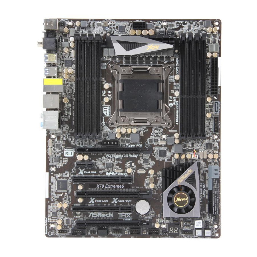
Page 12: Motherboard Layout (X79 Extreme6/Gb / X79 Extreme6)
1.3 Motherboard Layout (X79 Extreme6/GB / X79 Extreme6) 10 11 12 13 24.4cm (9.6 in) PWR_FAN1 ATX12V1 CPU_FAN2 CPU_FAN1 USB 3.0 T: USB0 B: USB1 USB 3.0 T: USB2 B: USB3 USB 2.0 Top: T: USB0 RJ-45 B: USB1 SLI/XFIRE_PWR1 2 oz Copper PCB PCIE1 SB_FAN1... -
Page 13: I/O Panel (X79 Extreme6/Gb / X79 Extreme6)
1.4 I/O Panel (X79 Extreme6/GB / X79 Extreme6) PS/2 Mouse Port (Green) Microphone (Pink) Coaxial SPDIF Out Port IEEE 1394 Port (IEEE 1394) LAN RJ-45 Port *** 12 eSATA3 Connector USB 2.0 Ports (USB45) USB 2.0 Ports (USB01) Side Speaker (Gray) USB 3.0 Ports (USB_23) Rear Speaker (Black) USB 3.0 Ports (USB_01) - Page 14 To enable Multi-Streaming function, you need to connect a front panel audio cable to the front panel audio header. After restarting your computer, you will fi nd “Mixer” tool on your system. Please select “Mixer ToolBox” , click “Enable playback multi-streaming”, and click “ok”.
-
Page 15: Asrock Game Blaster (X79 Extreme6/Gb)
PCIE Gold Fingers Coaxial SPDIF Out Port ASRock Game Blaster is a proprietary card instead of a standard PCI-E x1 card. Thus, it is only supported by some of ASRock’s motherboards. Please refer to ASRock’s website for the motherboard support list. - Page 16 DUMMY (3-pin HDMI_SPDIF1) SPDIF OUT **** The onboard audio will be disabled when ASRock Game Blaster is installed, but you can still enable it in the UEFI setup. If ASRock Game Blaster is installed, THX TruStudio function of the onboard audio Realtek ALC898 is not supported.
- Page 17 Specifications Platform - Size: 4.3-in x 3.0-in, 11.0 cm x 7.5 cm - Premium Gold Capacitor design (100% Japan-made high- quality Conductive Polymer Capacitors) Chipset - Creative Sound Core3D quad-core sound and voice processor - Powerful 32-bit 200Mhz QUAD-Processor SIMD DSP - 102dB 24-bit DAC - 101dB 24-bit ADC Output Features...
-
Page 18: Installation
Chapter 2: Installation This is an ATX form factor (12.0" x 9.6", 30.5 x 24.4 cm) motherboard. Before you install the motherboard, study the confi guration of your chassis to ensure that the motherboard fi ts into it. Make sure to unplug the power cord before installing or removing the motherboard. -
Page 19: Cpu Installation
2.3 CPU Installation Load Lever For the installation of Intel 2011-Pin CPU, please follow the steps below. Load Lever Contact Array Socket Body Load Plate 2011-Pin Socket Overview Before you insert the 2011-Pin CPU into the socket, please check if the CPU surface is unclean or if there are any bent pins in the socket. - Page 20 Step 2-2. Locate Pin1 and the two orientation key notches. orientation key notch alignment key Pin1 orientation key notch alignment key 2011-Pin CPU 2011-Pin Socket For proper inserting, please ensure to match the four orientation key notches of the CPU with the four alignment keys of the socket. Step 2-3.
-
Page 21: Installation Of Cpu Fan And Heatsink
2.4 Installation of CPU Fan and Heatsink This motherboard is equipped with 2011-Pin socket that supports Intel 2011-Pin CPU. Please adopt the type of heatsink and cooling fan compliant with Intel 2011- Pin CPU to dissipate heat. Before you installed the heatsink, you need to spray thermal interface material between the CPU and the heatsink to improve heat dis- sipation. -
Page 22: Installation Of Memory Modules (Dimm)
2.5 Installation of Memory Modules (DIMM) This motherboard provides eight 240-pin DDR3 (Double Data Rate 3) DIMM slots, and supports Quad Channel Memory Technology. For quad channel con- fi guration, you always need to install identical (the same brand, speed, size and chip-type) DDR3 DIMM in the slots, so that Quad Channel Memory Tech- nology can be activated. -
Page 23: Installing A Dimm
Installing a DIMM Please make sure to disconnect power supply before adding or removing DIMMs or the system components. Step 1. Unlock a DIMM slot by pressing the retaining clips outward. Step 2. Align a DIMM on the slot such that the notch on the DIMM matches the break on the slot. -
Page 24: Expansion Slots (Pci And Pci Express Slots)
Gigabit LAN card, SATA2 card, etc. PCIE4 (PCIE 3.0 x16 slot) is used for PCI Express x8 lane width graphics cards, ASRock Game Blaster, or used to install PCI Express graphics cards to support 3-Way CrossFireX or 3-Way SLI function. -
Page 25: Asrock Game Blaster Installation Guide (X79 Extreme6/Gb)
2.7 ASRock Game Blaster Installation Guide (X79 Extreme6/GB) 2.7.1 ASRock Game Blaster and Driver Installation Step 1. Please refer to the “Expansion Slots” section then insert ASRock Game Blaster into PCIE4 slot. Step 2. In order to avoid mechanical confl ict, please fasten your VGA cards and ASRock Game Blaster to the chassis with screws. - Page 26 Follow the step by step driver setup directions. Please make sure to use ® ® Windows Vista 32-bit / 64-bit or Windows 7 32-bit / 64-bit. ® ASRock Game Blaster is not supported under Windows XP / XP 64-bit. Step 4. Restart your computer for ASRock Game Blaster to take effect.
- Page 27 Some VGA cards violate the PCI-E spec and may result in mechanical confl ict with ASRock Game Blaster. In this case, we suggest you to follow the steps below to uninstall the chassis of the ASRock Game Blaster to fi x the confl ict.
-
Page 28: Asrock Game Blaster Configuration
2.7.2 ASRock Game Blaster Configuration This section explains how to confi gure your ASRock Game Blaster. 2.7.2.1 THX TRUSTUDIO PRO THX TruStudio Pro Click the power button on the left to activate or deactivate. Surround Control the level of audio immersion in music, movies and games. - Page 29 2.7.2.2 CRYSTALVOICE Select a recording device Mic Volume Control the level of mic volume. Mic Boost Control the level of mic boost. CrystalVoice Click the power button on the left to activate or deactivate. Morph your voice into different characters and accents. Smart Volume Be heard clearly without having to shout or whisper.
- Page 30 2.7.2.3 SPEAKERS/HEADPHONES Speakers / Headphones Confi guration Select the device connected. If there are both speakers and Optional Speakers: front headphones connected, please select the device you Center desire to use as audio output. Enable or disable center speaker. Subwoofer Enable or disable subwoofer.
- Page 31 2.7.2.4 MIXER Playback Speakers Control the level of speakers playback. SPDIF-Out Control the level of SPDIF-Out playback. Balance Control the level of various speaker’s balance. Input Device Select input device. What U Hear Control the level of playback redirect.
- Page 32 2.7.2.5 EQUALIZER Choose from Flat, Acoustic, Classical, Country, Dance, Jazz, New Age, Pop, Rock and Vocal. 2.7.2.6 JACK SETUP...
- Page 33 Device Connected: Select the device connected. 5.1 Surround Front Speakers Center/Subwoofer Rear Speakers 7.1 EX Surround Front Speakers Center/Subwoofer Rear Speakers Side Speakers Front panel headphones is shared with side speakers. Stereo and Microphone Speakers Microphone Stereo and Line-In Speakers Line-In Show Jack Setup dialog when an audio jack is inserted Enable or disable Jack Setup dialog.
- Page 34 2.7.2.7 ADVANCED FEATURES Play stereo mix to digital output Enable or disable play stereo mix to digital output.
- Page 35 2.7.2.8 PROFILE User Profi les You can save, load or delete your user profi les. The default is <Custom>.
- Page 36 Note 1. If you want to hear your own voice through the microphone (Playback mode). You can enable it by using ASRock Game Blaster's confi guration Utility CRYSTALVOICE Test. OR you can change your settings to "playback mode" by checking the "Listen to this device"...
-
Page 37: Sli Tm , 3-Way Sli Tm And Quad Sli
2.8 SLI , 3-Way SLI and Quad SLI Operation Guide ® This motherboard supports NVIDIA , 3-Way SLI and Quad SLI (Scalable Link Interface) technology that allows you to install up to three identical PCI Express ® ® x16 graphics cards. Currently, NVIDIA technology supports Windows XP / ®... - Page 38 Step3. Align and insert the ASRock SLI_Bridge_2S Card to the goldfi ngers on each graphics card. Make sure the ASRock SLI_Bridge_2S Card is fi rmly in place. ASRock SLI_Bridge_2S Card Step4. Connect a VGA cable or a DVI cable to the monitor connector or the DVI...
- Page 39 (Even the GPU chips version shall be the same.) Each graph- ics card should have two goldfi ngers for ASRock 3-Way SLI-2S1S Bridge Card connector. Insert one graphics card into PCIE1 slot, another graphics card to PCIE3 slot, and the other graphics card to PCIE4 slot.
-
Page 40: Driver Installation And Setup
2.8.2 Driver Installation and Setup Install the graphics card drivers to your system. After that, you can enable the Multi- ® Graphics Processing Unit (GPU) feature in the NVIDIA nView system tray utility. Please follow the below procedures to enable the multi-GPU feature. ®... - Page 41 ® For Windows Vista / Vista 64-bit / 7 / 7 64-bit OS: (For SLI and Quad SLI mode) A. Click the Start icon on your Windows taskbar. B. From the pop-up menu, select All Programs, and then click NVIDIA Corporation.
- Page 42 ® For Windows Vista / Vista 64-bit / 7 / 7 64-bit OS: (For 3-Way SLI mode) A. Follow steps A to D on page 41. B. From the pop-up menu, select Set SLI and PhysX confi guration. In Select a hardware acceleration setting for PhysX item, please select Enabled.
-
Page 43: Tm Tm
2.9 CrossFireX , 3-Way CrossFireX and Quad CrossFireX Operation Guide This motherboard supports CrossFireX , 3-way CrossFireX and Quad CrossFireX feature. CrossFireX technology offers the most advantageous means available of combining multiple high performance Graphics Processing Units (GPU) in a single PC. Combining a range of different operating modes with intelligent software design and an innovative interconnect mechanism, CrossFireX enables the highest possible level of performance and image quality in any 3D ®... - Page 44 Step 2. Connect two Radeon graphics cards by installing CrossFire Bridge on CrossFire Bridge Interconnects on the top of Radeon graphics cards. (CrossFire Bridge is provided with the graphics card you purchase, not bundled with this motherboard. Please refer to your graphics card vendor for details.) CrossFire Bridge Step 3.
- Page 45 2.9.1.2 Installing Three CrossFireX -Ready Graphics Cards Step 1. Install the identical 3-Way CrossFireX -ready graphics cards that are ® certified because different types of graphics cards will not work together properly. (Even the GPU chips version shall be the same.) Insert one graphics card into PCIE1 slot, another graphics card to PCIE3 slot, and the other graphics card to PCIE4 slot.
- Page 46 2.9.2 Driver Installation and Setup Step 1. Power on your computer and boot into OS. Step 2. Remove the AMD driver if you have any VGA driver installed in your system. The Catalyst Uninstaller is an optional download. We recommend using this utility to uninstall any previously installed Catalyst drivers prior to installation.
-
Page 47: Surround Display Features
Although you have selected the option “Enable CrossFire ”, the CrossFireX function may not work actually. Your computer will automatically reboot. After restarting your computer, please confi rm whether the option “Enable CrossFire ” in “ATI Catalyst Control Center” is selected or not; if not, please select it again, and then you are able to enjoy the benefi... -
Page 48: Asrock Smart Remote Installation Guide
The Multi-Angle CIR Receiver does not support Hot-Plug function. Please install it before you boot the system. * ASRock Smart Remote is only supported by some of ASRock motherboards. Please refer to ASRock website for the motherboard support list: http://www.asrock.com... -
Page 49: Jumpers Setup
2.12 Jumpers Setup The illustration shows how jumpers are setup. When the jumper cap is placed on pins, the jumper is “Short”. If no jumper cap is placed on pins, the jumper is “Open”. The illustration shows a 3-pin jumper whose pin1 and pin2 are “Short”... -
Page 50: Onboard Headers And Connectors
2.13 Onboard Headers and Connectors Onboard headers and connectors are NOT jumpers. Do NOT place jumper caps over these headers and connectors. Placing jumper caps over the headers and connectors will cause permanent damage of the motherboard! Serial ATA2 Connectors These four Serial ATA2 (SATA2) connectors support (SATA2_0_1: see p.12, No. - Page 51 (9-pin USB_8_9) USB_PWR (see p.12 No. 34) DUMMY USB_PWR USB 3.0 Header Besides four default USB 3.0 Vbus Vbus ports on the I/O panel, there is (19-pin USB3_4_5) Vbus IntA_P5_SSRX- IntA_P4_SSRX- IntA_P5_SSRX+ one USB 3.0 header on this (see p.12 No. 16) IntA_P4_SSRX+ IntA_P5_SSTX- motherboard.
- Page 52 ® For Windows 7 / 7 64-bit / Vista / Vista 64-bit OS: Go to the "FrontMic" Tab in the Realtek Control panel. Adjust “Recording Volume”. System Panel Header This header accommodates several system front panel (9-pin PANEL1) functions. (see p.12 No. 29) Connect the power switch, reset switch and system status indicator on the chassis to this header according to the pin assignments below.
- Page 53 Power LED Header Please connect the chassis power LED to this header to (3-pin PLED1) PLED- PLED+ PLED+ indicate system power status. (see p.12 No. 30) The LED is on when the system is operating. The LED keeps blinking in S1 state. The LED is off in S3/S4 state or S5 state (power off).
- Page 54 ATX Power Connector Please connect an ATX power supply to this connector. (24-pin ATXPWR1) (see p.12 No. 14) Though this motherboard provides 24-pin ATX power connector, it can still work if you adopt a traditional 20-pin ATX power supply. To use the 20-pin ATX power supply, please plug your power supply along with Pin 1 and Pin 13.
- Page 55 HDMI_SPDIF Header HDMI_SPDIF header, providing SPDIF audio output to HDMI (2-pin HDMI_SPDIF1) VGA card, allows the system to (see p.12 No. 42) SPDIFOUT connect HDMI Digital TV/ projector/LCD devices. Please connect the HDMI_SPDIF connector of HDMI VGA card to this header.
- Page 56 The Installation Guide of Front USB 3.0 Panel Step 1 Step 2 Screw the 2.5” HDD/SSD to the Front Prepare the bundled Front USB 3.0 Panel, four USB 3.0 Panel with four HDD screws. HDD screws, and six chassis screws. Step 3 Step 4 Screw the Front USB 3.0 Panel to the...
-
Page 57: Smart Switches
2.14 Smart Switches The motherboard has three smart switches: power switch, reset switch and clear CMOS switch, allowing users to quickly turn on/off or reset the sytem clear the CMOS values. Power Switch Power Switch is a smart switch, allowing users to quickly turn (PWRBTN) on/off the system. -
Page 58: Dr. Debug
2.15 Dr. Debug Dr. Debug is used to provide code information, which makes troubleshooting even easier. Please see the diagrams below for reading the Dr. Debug codes. Status Code Description 0x00 Not used 0x01 Power on. Reset type detection (soft/hard) 0x02 AP initialization before microcode loading 0x03... - Page 59 0x37 Post-Memory North Bridge initialization is started 0x38 Post-Memory North Bridge initialization (North Bridge module specifi c) 0x39 Post-Memory North Bridge initialization (North Bridge module specifi c) 0x3A Post-Memory North Bridge initialization (North Bridge module specifi c) 0x3B Post-Memory South Bridge initialization is started 0x3C Post-Memory South Bridge initialization (South Bridge module specifi...
- Page 60 0x62 Installation of the South Bridge Runtime Services 0x63 CPU DXE initialization is started 0x64 CPU DXE initialization (CPU module specifi c) 0x65 CPU DXE initialization (CPU module specifi c) 0x66 CPU DXE initialization (CPU module specifi c) 0x67 CPU DXE initialization (CPU module specifi c) 0x68 PCI host bridge initialization 0x69...
- Page 61 0xA6 SCSI Detect 0xA7 SCSI Enable 0xA8 Setup Verifying Password 0xA9 Start of Setup 0xAA Reserved for ASL (see ASL Status Codes section below) 0xAB Setup Input Wait 0xAC Reserved for ASL (see ASL Status Codes section below) 0xAD Ready To Boot event 0xAE Legacy Boot event 0xAF...
-
Page 62: Serial Ata (Sata) / Serial Ataii (Sataii) Hard Disks Installation
2.16 Serial ATA (SATA) / Serial ATA2 (SATA2) Hard Disks Installation ® This motherboard adopts Intel X79 chipset that supports Serial ATA (SATA) / Serial ATA2 (SATA2) hard disks and RAID (RAID 0, RAID 1, RAID 5, RAID 10 and Intel Rapid Storage 3.0) functions. -
Page 63: Hot Plug And Hot Swap Functions For Sata / Sataii Hdds
2.18 Hot Plug and Hot Swap Functions for SATA / SATA2 HDDs This motherboard supports Hot Plug and Hot Swap functions for SATA / SATA2 in ® RAID / AHCI mode. Intel X79 chipset provides hardware support for Advanced Host controller Interface (AHCI), a new programming interface for SATA host controllers developed through a joint industry effort. -
Page 64: Sata / Sataii / Sata3 Hdd Hot Plug Feature And Operation Guide
SATA / SATA2 / SATA3 Hot Plug support information of our motherboard is indicated in the product spec on our website: www.asrock.com 2. Make sure your SATA / SATA2 / SATA3 HDD can support Hot Plug function from your dealer or HDD user manual. - Page 65 How to Hot Plug a SATA / SATA2 / SATA3 HDD: Points of attention, before you process the Hot Plug: Please do follow below instruction sequence to process the Hot Plug, improper procedure will cause the SATA / SATA2 / SATA3 HDD damage and data loss. Step 1 Step 2 Please connect SATA power cable 1x4-...
-
Page 66: Driver Installation Guide
2.21 Driver Installation Guide To install the drivers to your system, please insert the support CD to your optical drive fi rst. Then, the drivers compatible to your system can be auto-detected and listed on the support CD driver page. Please follow the order from up to bottom side to install those required drivers. -
Page 67: Installing Windows
® After the installation of Windows 7 / 7 64-bit / Vista / Vista 64-bit OS, if you want to manage RAID functions, you are allowed to use both “RAID Installation Guide” and “Intel Rapid Storage Information” for RAID confi guration. Please refer to the document in the Support CD, “Guide to SATA Hard Disks Installation and RAID Confi... -
Page 68: Vista Tm 64-Bit Without Raid Functions
2.23.2 Installing Windows 7 / 7 64-bit / Vista / Vista 64-bit ® Without RAID Functions ® If you want to install Windows 7 / 7 64-bit / Vista / Vista 64-bit OS on your SATA / SATA2 / SATA3 HDDs without RAID functions, please follow below steps. Using SATA / SATA2 / SATA3 HDDs with NCQ function STEP 1: Set Up UEFI. -
Page 69: Teaming Function Operation Guide (X79 Extreme6/Gb)
2.24 Teaming Function Operation Guide (X79 Extreme6/GB) Dual LAN with Teaming function enabled on this motherboard allows two single connections to act as one single connection for twice the transmission bandwidth, making data transmission more effective and improving the quality of transmission of distant images. - Page 70 4. Click the Create Team tab. * The Create Team tab appears only if there are teamable adapters available. 5. Click the Team Name fi eld to enter a team name. 6. Click the Team Type fi eld to select a team type. 7.
- Page 71 9. Type the value for Team MTU. 10. Click Create to save the team information. 11. Repeat steps 5. through 10. to defi ne additional teams. As teams are defi ned, they can be selected from the team list, but they have not yet been created. Click the Preview tab to view the team structure before applying the changes.
-
Page 72: Untied Overclocking Technology
14. Confi gure the team IP address. a. From Control Panel, double-click Network Connections. b. Right-click the name of the team to be confi gured, and then click Properties. c. On the General tab, click Internet Protocol (TCP/IP), and then click Properties. -
Page 73: Uefi Setup Utility
Chapter 3: UEFI SETUP UTILITY 3.1 Introduction This section explains how to use the UEFI SETUP UTILITY to confi gure your system. The UEFI chip on the motherboard stores the UEFI SETUP UTILITY. You may run the UEFI SETUP UTILITY when you start up the computer. Please press <F2>... -
Page 74: Navigation Keys
3.1.2 Navigation Keys Please check the following table for the function description of each navigation key. Navigation Key(s) Function Description Moves cursor left or right to select Screens Moves cursor up or down to select items + / - To change option for the selected items <Enter>... - Page 75 X79 Extreme6 System Browser System Browser can let you easily check your current system confi guration in UEFI setup.
-
Page 76: Oc Tweaker Screen
3.3 OC Tweaker Screen In the OC Tweaker screen, you can set up overclocking features. Load CPU EZ OC Setting You can use this option to load CPU EZ overclocking settings. Please note that overclocking may cause damage to your CPU and motherboard. It should be done at your own risk and expense. - Page 77 Turbo Boost Power Limit Use this item to adjust Turbo Boost power limit. Confi guration options: [Auto] and [Manual]. The default value is [Auto]. Core Current Limit Maximum instantaneous current allowed at any given time. Additional Turbo Voltage Use this item to add voltage when CPU is in Turbo mode. Active Processor Cores Use this item to select the number of cores to enable in each processor package.
- Page 78 DRAM tRCD Use this item to change RAS# to CAS# Delay (tRCD) Auto/Manual setting. The default is [Auto]. DRAM tRP Use this item to change Row Precharge Time (tRP) Auto/Manual setting. The default is [Auto]. DRAM tRAS Use this item to change RAS# Active Time (tRAS) Auto/Manual setting. The default is [Auto].
- Page 79 ODT NOM (CH A) Use this item to change ODT NOM (CH A) Auto/20/30/40/60/120 setting. The default is [Auto]. ODT WR (CH B) Use this item to change ODT WR (CH B) Auto/60/120 setting. The default is [Auto]. ODT NOM (CH B) Use this item to change ODT NOM (CH B) Auto/20/30/40/60/120 setting.
- Page 80 Voltage Control Voltage Confi guration VRM Protection Use this to enable or disable Vcore Power Over Temperature Protection. The default value is [Enabled]. CPU Core Voltage Use this to select CPU Core Voltage. The default value is [Auto]. CPU Load-Line Calibration CPU Load-Line Calibration helps prevent CPU voltage droop when the system is under heavy load.
-
Page 81: Advanced Screen
3.4 Advanced Screen In this section, you may set the confi gurations for the following items: CPU Confi gu- ration, North Bridge Confi guration, South Bridge Confi guration, Storage Confi gura- tion, Super IO Confi guration, ACPI Confi guration, USB Confi guration and ME Sub- system. -
Page 82: Cpu Confi Guration
3.4.1 CPU Configuration CPU Ratio Setting Use this item to change the ratio value of this motherboard. Intel Hyper Threading Technology To enable this feature, it requires a computer system with an Intel processor that supports Hyper-Threading technology and an operating ®... - Page 83 CPU Power Management Confi guration Intel SpeedStep Technology Intel SpeedStep technology is Intel’s new power saving technology. Pro- cessor can switch between multiple frequency and voltage points to en- able power savings. The default value is [Enabled]. Confi guration options: ®...
-
Page 84: North Bridge Confi Guration
3.4.2 North Bridge Configuration Primary Graphics Adapter This allows you to select the boot graphic adapter priority. The default value is [PCI Express]. PCIE 1 Link Speed This allows you to select PCIE 1 Link Speed. The default value is [GEN2]. PCIE 3 Link Speed This allows you to select PCIE 3 Link Speed. -
Page 85: South Bridge Confi Guration
Select [Auto], [Enabled] or [Disabled] for the onboard HD Audio feature. If you select [Auto], the onboard HD Audio will be disabled when PCI Sound Card or ASRock Game Blaster is plugged. Front Panel Select [Auto] or [Disabled] for the onboard HD Audio Front Panel. - Page 86 Good Night LED Use this item to enable or disable Power LED and Lan LED. Onboard Debug Port LED Use this item to enable or disable Onboard Debug Port LED.
-
Page 87: Storage Confi Guration
3.4.4 Storage Configuration SATA Mode This item is for SATA3_0, SATA3_1 and SATA2_0 to SATA2_3 ports. Use this to select SATA mode. Confi guration options: [IDE Mode], [AHCI Mode], [RAID Mode] and [Disabled]. The default value is [AHCI Mode]. AHCI (Advanced Host Controller Interface) supports NCQ and other new features that will improve SATA disk performance but IDE mode does not have these advantages. -
Page 88: Super Io Confi Guration
3.4.5 Super IO Configuration Serial Port Use this item to enable or disable the onboard serial port. Serial Port Address Use this item to set the address for the onboard serial port. Confi guration options: [3F8h / IRQ4] and [3E8h / IRQ4]. Infrared Port Use this item to enable or disable the onboard infrared port. -
Page 89: Acpi Confi Guration
3.4.6 ACPI Configuration Suspend to RAM Use this item to select whether to auto-detect or disable the Suspend-to- RAM feature. Select [Auto] will enable this feature if the OS supports it. Check Ready Bit Use this item to enable or disable the feature Check Ready Bit. PS/2 Keyboard Power On Use this item to enable or disable PS/2 keyboard to turn on the system from the power-soft-off mode. -
Page 90: Usb Confi Guration
3.4.7 USB Configuration USB 2.0 Controller Use this item to enable or disable the use of USB 2.0 controller. USB 3.0 Controller Use this item to enable or disable the use of USB 3.0 controller. Legacy USB Support Use this option to select legacy support for USB devices. There are four confi... -
Page 91: Me Subsystem
3.4.8 ME Subsystem Intel ME Subsystem Confi guration ME Version... -
Page 92: Hardware Health Event Monitoring Screen
This allows you to set the SB fan 1 speed. Confi guration options: [Full On] and [Automatic mode]. The default value is [Automatic mode]. Target SB Temperature This allows you to set the target temperature to activate ASRock X-FAN. The default value is [50 C/122 Target Fan Speed This allows you to set the target fan speed. -
Page 93: Boot Screen
3.6 Boot Screen In this section, it will display the available devices on your system for you to confi g- ure the boot settings and the boot priority. Setup Prompt Timeout This shows the number of seconds to wait for setup activation key. 65535(0XFFFF) means indefi... -
Page 94: Security Screen
3.7 Security Screen In this section, you may set or change the supervisor/user password for the system. For the user password, you may also clear it. -
Page 95: Exit Screen
3.8 Exit Screen Save Changes and Exit When you select this option, it will pop-out the following message, “Save confi guration changes and exit setup?” Select [Yes] to save the changes and exit the UEFI SETUP UTILITY. Discard Changes and Exit When you select this option, it will pop-out the following message, “Discard changes and exit setup?”... -
Page 96: Software Support
Click on a specifi c item then follow the installation wizard to install it. 4.2.4 Contact Information If you need to contact ASRock or want to know more about ASRock, welcome to visit ASRock’s website at http://www.asrock.com; or you may contact your... - Page 97 Installing OS on a HDD Larger Than 2TB in AHCI Mode ® This motherboard adopts UEFI BIOS that allows Windows OS to be installed on a large size HDD (>2TB). Please follow the procedures below to install the operating system. ®...
-
Page 98: Installing Os On A Hdd Larger Than 2Tb In Raid Mode
RAID drivers into a USB fl ash disk. You can download the driver from ASRock's website and unzip the fi le into a USB fl ash disk OR copy the fi le from ASRock motherboard support CD. (please copy the fi les under following directory: 32 bit: ..\i386\Win7_Vista_Intel_v3.0.0.1112... - Page 99 E. Please keep the USB fl ash disk installed until the system fi rst reboot. ® F. Continue to install OS by following the Windows instructions. ® 5. Follow Windows Installation Guide to install OS. ® If you install Windows 7 64-bit / Vista 64-bit in a large hard disk (ex.
- Page 100 B. Disable “Volume Shadow Copy” service. a. Type “computer management” in the Start Menu, then press “Enter”. b. Go to “Services and Applications>Services”; Then double click “Volume Shadow Copy”.
- Page 101 c. Set “Startup type” to “Disable” then Click “OK”. C. Reboot your system. D. After reboot, please start to install motherboard drivers and utilities. ® Windows 7 64-bit: A. Please request the hotfi x KB2505454 through this link: http://support.microsoft.com/kb/2505454/ ® B.