Table of Contents
Advertisement
Quick Links
Advertisement
Table of Contents

Related Manuals for Asus P5N73-AM


Summary of Contents for Asus P5N73-AM
- Page 1 P5N73-AM...
- Page 2 Product warranty or service will not be extended if: (1) the product is repaired, modified or altered, unless such repair, modification of alteration is authorized in writing by ASUS; or (2) the serial number of the product is defaced or missing.
-
Page 3: Table Of Contents
Welcome! ..................1-2 Package contents ................. 1-2 Special features ................1-2 1.3.1 Product highlights ............1-2 1.3.2 ASUS Special features ........... 1-4 Before you proceed ..............1-5 Motherboard overview ..............1-6 1.5.1 Placement direction ............1-6 1.5.2 Screw holes ..............1-6 1.5.3... - Page 4 Managing and updating your BIOS ..........2-2 2.1.1 ASUS Update utility ............2-2 2.1.2 Creating a bootable floppy disk ........2-5 2.1.3 ASUS EZ Flash 2 utility ........... 2-6 2.1.4 Updating the BIOS ............2-7 2.1.5 Saving the current BIOS file ..........2-9 2.1.6 ASUS CrashFree BIOS 2 utility ........
- Page 5 Removable Drives ............2-33 2.6.4 Boot Settings Configuration ......... 2-34 2.6.5 Security ................. 2-36 Tools menu ................. 2-37 ASUS EZ Flash 2 ................. 2-37 Exit menu ..................2-38 Chpater 3: Software Support Installing an operating system ........... 3-2 Support CD information .............. 3-2 3.2.1...
-
Page 6: Notices
Notices Federal Communications Commission Statement This device complies with Part 15 of the FCC Rules. Operation is subject to the following two conditions: • This device may not cause harmful interference, and • This device must accept any interference received including interference that may cause undesired operation. -
Page 7: Safety Information
Safety information Electrical safety • To prevent electrical shock hazard, disconnect the power cable from the electrical outlet before relocating the system. • When adding or removing devices to or from the system, ensure that the power cables for the devices are unplugged before the signal cables are connected. -
Page 8: About This Guide
Refer to the following sources for additional information and for product and software updates. ASUS websites The ASUS website provides updated information on ASUS hardware and software products. Refer to the ASUS contact information. Optional documentation Your product package may include optional documentation, such as warranty flyers, that may have been added by your dealer. -
Page 9: Conventions Used In This Guide
Conventions used in this guide To make sure that you perform certain tasks properly, take note of the following symbols used throughout this manual. DANGER/WARNING: Information to prevent injury to yourself when trying to complete a task. CAUTION: Information to prevent damage to the components when trying to complete a task. -
Page 10: P5N73-Am Specifications Summary
Supports Enhanced Intel SpeedStep Technology (EIST) ® Supports Intel Hyper-Threading Technology ® *Refer to www.asus.com for Intel CPU support list Chipset NVIDIA GeForce 7050 / nForce 610i (MCP73V) Front Side Bus 1333 / 1066 / 800 / 533 MHz Memory... - Page 11 ATX 12V 2.0 compliant Manageability WOL, PXE, WOR by Ring, PME Wake UP Support CD contents Drivers ASUS PC Probe II ASUS Update Anti-virus software Form factor MicroATX Form Factor: 9.6 in x 7.6 in (24.5 cm x 19.3 cm)
-
Page 13: Chapter 1: Product Introduction
This chapter describes the motherboard features and the new technologies it supports. Product introduction... -
Page 14: Welcome
Green ASUS This motherboard and its packaging comply with the European Union’s Restriction on the use of Hazardous Substances (RoHS). This is in line with the ASUS vision of creating environment-friendly and recyclable products/packaging to safeguard consumers’ health while minimizing the impact on the environment. - Page 15 See page 1-30 for details. High Definition Audio Enjoy high-end sound quality on your PC! The onboard 8-channel HD audio (High Definition Audio, previously codenamed Azalia) CODEC enables high-quality 192KHz/24-bit audio output, jack-detect feature. ASUS P5N73-AM...
-
Page 16: Asus Special Features
1.3.2 ASUS Special features ASUS Q-Fan technology The ASUS Q-Fan technology smartly adjusts the fan speeds according to the system loading to ensure quiet, cool, and efficient operation. See page 2-32 for details. ASUS MyLogo2™ This feature allows you to convert your favorite photo into a 256-color boot logo for a more colorful and vivid image on your screen. -
Page 17: Before You Proceed
ON, in sleep mode, or in soft-off mode. This is a reminder that you should shut down the system and unplug the power cable before removing or plugging in any motherboard component. The illustration below shows the location of the onboard LED. SB_PWR Standby Powered Power P5N73-AM Onboard LED ASUS P5N73-AM... -
Page 18: Motherboard Overview
Motherboard overview Before you install the motherboard, study the configuration of your chassis to ensure that the motherboard fits into it. Ensure to unplug the power cord before installing or removing the motherboard. Failure to do so can cause you physical injury and damage motherboard components. -
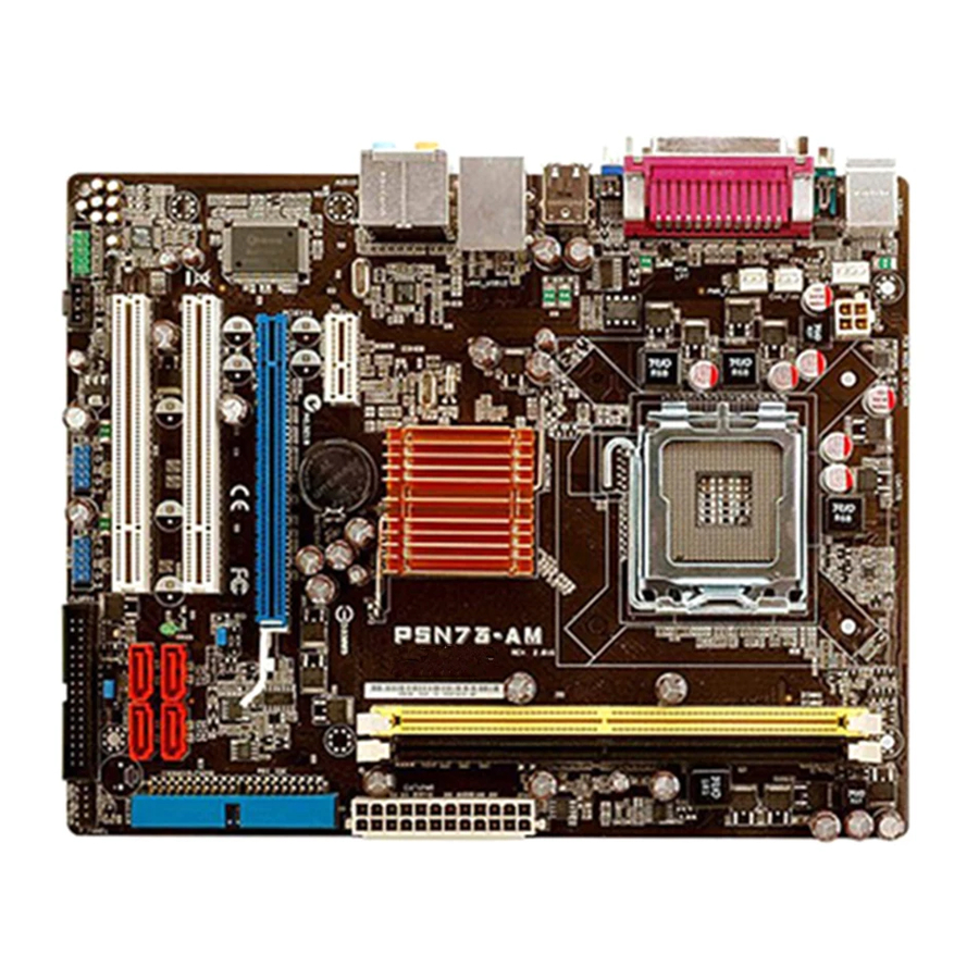
Page 19: Motherboard Layout
B: Keyboard COM1 ATX12V CHA_FAN LGA775 PWR_FAN VGA1 BIOS USB34 LAN1_USB12 MCP73V AUDIO 8201CP CR2032 3V PCIEX1_1 Lithium Cell CMOS Power PCIEX16 PCI1 CLRTC SATA1 SATA2 SATA4 SATA3 SB_PWR PCI2 VT1708B CHASSIS SPDIF_OUT FLOPPY SPEAKER USB56 USB78 AAFP ASUS P5N73-AM... -
Page 20: Central Processing Unit (Cpu)
Contact your retailer immediately if the PnP cap is missing, or if you see any damage to the PnP cap / socket pins/motherboard components. ASUS will shoulder the cost of repair only if the damage is shipment/transit-related. - Page 21 Lift the load lever in the direction of the arrow to a 135º angle. Lift the load plate with your thumb and forefinger to a 100º angle (A), then push the PnP cap from the load plate window to remove (B). Load plate ASUS P5N73-AM...
- Page 22 Position the CPU over the socket, ensuring that the gold triangle is on the bottom-left corner of the socket. The socket alignment key should fit into the CPU notch. Alignment key Gold triangle mark Close the load plate (A), then push the load lever (B) until it snaps into the retention tab.
-
Page 23: Installling The Cpu Heatsink And Fan
Place the heatsink on top of the installed CPU, ensuring that the four fasteners match the holes on the motherboard. Fastener Motherboard hole Ensure that each fastener is oriented as shown, with the narrow groove directed outward. ASUS P5N73-AM 1-11... - Page 24 Push down two fasteners at a time in a diagonal sequence to secure the heatsink and fan assembly in place. When the fan and heatsink assembly is in place, connect the CPU fan cable to the connector on the motherboard labeled CPU_FAN. P5N73-AM CPU Fan Connector •...
-
Page 25: Uninstalling The Cpu Heatsink And Fan
To uninstall the CPU heatsink and fan: Disconnect the CPU fan cable from the connector on the motherboard. Rotate each fastener counterclockwise. Pull up two fasteners at a time in a diagonal sequence to disengage the heatsink and fan assembly from the motherboard. ASUS P5N73-AM 1-13... - Page 26 Remove the heatsink and fan assembly from the motherboard. Rotate each fastener clockwise to reset the orientation. Narrow end of the groove The narrow end of the groove should point outward after resetting. (The photo shows the groove shaded for emphasis.) 1-14 Chapter 1: Product introduction...
-
Page 27: System Memory
This motherboard only supports single-channel configuration. • Always install DIMMs with the same CAS latency. For optimum compatibility, it is recommended that you obtain memory modules from the same vendor. Refer to the DDR2 Qualified Vendors List on next page for details. ASUS P5N73-AM 1-15... -
Page 28: Ddr2 Qualified Vendors List
DDR2 Qualified Vendors List The following table lists the memory modules that have been tested and qualified for use with this motherboard. Visit the ASUS website (www.asus.com) for the latest DDR2 DIMM modules for this motherboard. DDR2 800 Qualified Vendors List... - Page 29 M20AD5G3H3166I1C52 ADATA AD29608A8A-3EG20648 • • 512MB ADATA M20AD5G3H3166I1C52 ADATA AD29608A8A-3EG20718 • • ADATA M2OAD5G3I4176I1C52 ADATA AD29608A8A-3EG20645 • • ADATA M2OAD5H3J4170I1C53 ADATA AD20908A8A-3EG 30724 • • 512MB VDATA M2GVD5G3H31A4I1C52 VDATA VD29608A8A-3EC20615 • • (continued on the next page) ASUS P5N73-AM 1-17...
- Page 30 DDR2 667 Qualified Vendors List DIMM support Size Vendor Model Brand Component 512MB VDATA M2YVD5G3H31P4I1C52 VDATA VD29608A8A-3EG20627 • • 512MB VDATA M2GVD5G3H166I1C52 VDATA VD29608A8A-3EG20637 • • VDATA M2GVD5G3I41P6I1C52 VDATA VD29608A8A-3EG20627 • • VDATA M2GVD5G3I41C4I1C52 VDATA VD29608A8A-3EC20620 • • VDATA M2GVD5G3I4176I1C52 VDATA VD29608A8A-3EG20641 •...
- Page 31 • 512MB TAKEMS TMS51B264C081-534AE takeMS MS18T51280-3.7EA07100 • • TAKEMS TMS1GB264C081-534AE takeMS MS18T51280-3.7EA0651D • • TAKEMS TMS1GB264C081-534QI takeMS MS18T51280-3.7 • • TAKEMS TMS1GB264C081-534AP takeMS MS18T51280-3.7P0645D • • 512MB VERITECH GTP512HLTM46DG VERITECH VTD264M8PC6G01A164129621 • (continued on the next page) ASUS P5N73-AM 1-19...
-
Page 32: Installing A Dimm
• B*: Supports two modules inserted into both slots as Single-channel memory configuration. Visit the ASUS website for the latest DDR2-533/667/800 MHz QVL. 1.7.4 Installing a DIMM Unplug the power supply before adding or removing DIMMs or other system components. Failure to do so can cause severe damage to both the motherboard and the components. -
Page 33: Removing A Dimm
Align the card connector with the slot and press firmly until the card is completely seated on the slot. Secure the card to the chassis with the screw you removed earlier. Replace the system cover. ASUS P5N73-AM 1-21... -
Page 34: Configuring An Expansion Card
1.8.2 Configuring an expansion card After installing the expansion card, configure it by adjusting the software settings. Turn on the system and change the necessary BIOS settings, if any. See Chapter 2 for information on BIOS setup. Assign an IRQ to the card. Refer to the tables on the next page. Install the software drivers for the expansion card. - Page 35 When using PCI cards on shared slots, ensure that the drivers support “Share IRQ” or that the cards do not need IRQ assignments. Otherwise, conflicts will arise between the two PCI groups, making the system unstable and the card inoperable. ASUS P5N73-AM 1-23...
-
Page 36: Pci Slots
1.8.4 PCI slots The PCI slots support cards such as a LAN card, SCSI card, USB card, and other cards that comply with PCI specifications. The figure shows a LAN card installed on a PCI slot. If you install a PCI graphics card, we recommend that you remove the onboard graphics card driver. -
Page 37: Jumper
Hold down the <Del> key during the boot process and enter BIOS setup to re-enter data. Except when clearing the RTC RAM, never remove the cap on CLRTC jumper default position. Removing the cap will cause system boot failure! CLRTC Normal Clear RTC (Default) P5N73-AM Clear RTC RAM ASUS P5N73-AM 1-25... -
Page 38: 1.10 Connectors
1.10 Connectors 1.10.1 Rear panel connectors PS/2 mouse port (green). This port is for a PS/2 mouse. Parallel port. This 25-pin port connects a parallel printer, a scanner, or other devices. LAN (RJ-45) port. Supported by 10/100 LAN controller, this port allows 100Mb connection to a Local Area Network (LAN) through a network hub. -
Page 39: Internal Connectors
Pin 5 on the connector is removed to prevent incorrect cable connection when using an FDD cable with a covered Pin 5. FLOPPY PIN1 NOTE: Orient the red markings on the floppy ribbon cable to PIN 1. Floppy Disk Drive Connector P5N73-AM ASUS P5N73-AM 1-27... - Page 40 IDE connector (40-1 pin PRI_IDE) The onboard IDE connector is for Ultra DMA 100/66/33 signal cable. There are three connectors on each Ultra DMA 100/66/33 signal cable: blue, black, and gray. Connect the blue connector to the motherboard’s IDE connector, then select one of the following modes to configure your device(s).
- Page 41 These connectors are for the Serial ATA signal cables for Serial ATA hard disk drives. P5N73-AM SATA Connectors Speaker connector (4-pin SPEAKER) This 4-pin connector is for the chassis-mounted system warning speaker. The speaker allows you to hear system beeps and warnings. SPEAKER P5N73-AM Speaker Out Connector ASUS P5N73-AM 1-29...
- Page 42 CPU, Chassis and Power fan connectors (4-pin CPU_FAN, 3-pin CHA_FAN, 3-pin PWR_FAN) The fan connectors support cooling fans of a total of 1A~2.2A (26.4W max.) at +12V. Connect the fan cables to the fan connectors on the motherboard, ensuring that the black wire of each cable matches the ground pin of the connector.
- Page 43 +5 Volts +12 Volts +5 Volts +5V Standby +5 Volts Power OK -5 Volts Ground Ground +5 Volts Ground Ground Ground +5 Volts PSON# Ground Ground +3 Volts -12 Volts +3 Volts +3 Volts P5N73-AM ATX Power Connector ASUS P5N73-AM 1-31...
- Page 44 Optical drive audio connector (4-pin CD) This connector allows you to receive stereo audio input from sound sources such as a CD-ROM, TV tuner, or MPEG card. (black) P5N73-AM Internal Audio Connector Enable the CD-IN function in the audio utility when using this connector. USB connectors (10-1 pin USB56, USB78) These connectors are for USB 2.0 ports.
-
Page 45: Front Panel Audio Connector
By default, the pins labeled “Chassis Signal” and “Ground” are shorted with a jumper cap. Remove the jumper caps only when you intend to use the chassis intrusion detection feature. CHASSIS (Default) P5N73-AM Intrusion Connector ASUS P5N73-AM 1-33... -
Page 46: System Panel Connector
12. System panel connector (10-1 pin F_PANEL) This connector supports several chassis-mounted functions. F_PANEL PLED PWRBTN +HDLED RESET P5N73-AM System Panel Connector • System power LED (2-pin PLED) This 2-pin connector is for the system power LED. Connect the chassis power LED cable to this connector. -
Page 47: Chapter 2: Bios Setup
This chapter tells how to change the system settings through the BIOS Setup menus. Detailed descriptions of the BIOS parameters are also provided. BIOS setup... -
Page 48: Managing And Updating Your Bios
ASUS Update: Updates the BIOS in Windows environment. ® ASUS EZ Flash 2: Updates the BIOS using a floppy disk/ USB flash disk or the motherboard support CD / DVD. AwardBIOS Flash Utility: Updates the BIOS in DOS mode using a bootable floppy disk. - Page 49 To update the BIOS through the Internet: desktop by clicking Start Launch the ASUS Update utility from the Windows ® > Programs > ASUS > ASUSUpdate > ASUSUpdate. The ASUS Update main window appears. Select Update BIOS from Select the ASUS FTP site nearest...
- Page 50 To update the BIOS through a BIOS file: Launch the ASUS Update utility from the Windows desktop by clicking Start ® > Programs > ASUS > ASUSUpdate > ASUSUpdate. The ASUS Update main window appears. Select Update BIOS from a file option from the drop-down menu, then click Next.
-
Page 51: Creating A Bootable Floppy Disk
Right-click Floppy Disk Drive then click Format to display the Format 3 1/2 Floppy dialog box. d. Select the Create an MS-DOS startup disk check box. e. Click Start. Copy the original or the latest motherboard BIOS file to the bootable floppy disk. ASUS P5N73-AM... -
Page 52: Asus Ez Flash 2 Utility
2.1.3 ASUS EZ Flash 2 utility The ASUS EZ Flash 2 feature allows you to update the BIOS without having to go through the long process of booting from a floppy disk and using a DOS-based utility. The EZ Flash 2 utility is built-in the BIOS chip so it is accessible by pressing <Alt>... -
Page 53: Updating The Bios
Flash Utility. Follow these instructions to update the BIOS using this utility. Download the latest BIOS file from the ASUS web site. Rename the file to P5N73-AM.BIN and save it to a floppy disk, CD ROM or a USB flash disk in FAT 16/12 format. - Page 54 Press <N> when the utility prompts you to save the current BIOS file. The following screen appears. The utility verifies the BIOS AwardBIOS Flash Utility for ASUS V1.17 file in the floppy disk, CD (C) Phoenix Technologies Ltd. All Rights Reserved...
-
Page 55: Saving The Current Bios File
To save the current BIOS file using the AwardBIOS Flash Utility: Follow steps 1 to 6 of the AwardBIOS Flash Utility for ASUS V1.17 previous section. (C) Phoenix Technologies Ltd. All Rights Reserved Press <Y> when the utility... -
Page 56: Asus Crashfree Bios 2 Utility
2.1.6 ASUS CrashFree BIOS 2 utility The ASUS CrashFree BIOS 2 is an auto recovery tool that allows you to restore the BIOS file when it fails or gets corrupted during the updating process. You can update a corrupted BIOS file using the motherboard support DVD or the floppy disk that contains the updated BIOS file. - Page 57 Reading file “P5N73-AM.bin”. Completed. Start flashing... Restart the system after the utility completes the updating process. The recovered BIOS may not be the latest BIOS version for this motherboard. Visit the ASUS website (www.asus.com) to download the latest BIOS file. ASUS P5N73-AM 2-11...
-
Page 58: Bios Setup Program
The BIOS setup screens shown in this section are for reference purposes only, and may not exactly match what you see on your screen. • Visit the ASUS website (www.asus.com) to download the latest BIOS file for this motherboard. 2-12... -
Page 59: Bios Menu Screen
• The BIOS setup screens shown in this chapter are for reference purposes only, and may not exactly match what you see on your screen. • Visit the ASUS website (www.asus.com) to download the latest BIOS information. ASUS P5N73-AM 2-13... -
Page 60: Legend Bar
2.2.3 Legend bar At the bottom of the Setup screen is a legend bar. The keys in the legend bar allow you to navigate through the various setup menus. The following table lists the keys found in the legend bar with their corresponding functions. Navigation Key Function <F1>... -
Page 61: Pop-Up Window
[1.44M, 3.5 in. Specifies the capacity and physical size of diskette Legacy Diskette A: Primary IDE Master [ST321122A] drive A. Primary IDE Slave [ASUS CDS520/A] Disabled ..[ ] SATA1 [None] 720K , 3.5 in..[ ] SATA2 [None] 1.44M, 3.5 in. -
Page 62: Main Menu
Main menu When you enter the BIOS Setup program, the Main menu screen appears, giving you an overview of the basic system information. Refer to section “2.2.1 BIOS menu screen” for information on the menu screen items and how to navigate through them. Phoenix-Award BIOS CMOS Setup Utility Main Advanced... -
Page 63: Primary Ide Master/Slave
[None]. Configuration options: [None] [Auto] [Manual] Access Mode [Auto] The default [Auto] allows automatic detection of an IDE hard disk drive. Select [CHS] for this item if you set the Primary IDE Master/Slave to [Manual]. Configuration options: [CHS] [LBA] [Large] [Auto] ASUS P5N73-AM 2-17... - Page 64 Before attempting to configure a hard disk drive, ensure you have the correct configuration information supplied by the drive manufacturer. Incorrect settings may cause the system to fail to recognize the installed hard disk. Capacity Displays the auto-detected hard disk capacity. This item is not configurable. Cylinder Shows the number of the hard disk cylinders.
-
Page 65: Sata 1~4
Displays the auto-detected hard disk capacity. This item is not configurable. Cylinder Shows the number of the hard disk cylinders. This item is not configurable. Head Shows the number of the hard disk read/write heads. This item is not configurable. ASUS P5N73-AM 2-19... -
Page 66: Hdd Smart Monitoring
Landing Zone Shows the number of landing zone per track. This item is not configurable. Sector Shows the number of sectors per track. This item is not configurable. After entering the IDE hard disk drive information into BIOS, use a disk utility, such as FDISK, to partition and format new IDE hard disk drives. -
Page 67: Advanced Menu
FSB - Memory Ratio [Auto] Allows you to select the FSB memory ratio. This item becomes user- configurabled when the FSB - Memory Clock Mode item is set to [Linked]. Configuration options: [Auto] [1:1] [5:4] [3:2] [Sync Mode] ASUS P5N73-AM 2-21... -
Page 68: Memory Timing Setting
FSB (QDR), MHz [Auto] Allows you to adjust CPU FSB frequency from 400 to 2400. You may enter a new value or use +/- keys to adjust. This item becomes user-configurabled when the FSB - Memory Clock Mode item is set to [Linked] or [Unlinked]. The Actual FSB (QDR) reflects the actual frequency that takes effect on a reboot. - Page 69 1.35V Over Voltage Control [Disabled] Allows you to adjust the +1.35V over voltage. Configuration options: [Enabled] [Disable] VCORE Over Voltage Control [Disabled] Allows you to adjust the VCORE over voltage. Configuration options: [Disabled] [+50 mV] [+100 mV] [+150 mV] ASUS P5N73-AM 2-23...
-
Page 70: Cpu Configuration
2.4.2 CPU Configuration Phoenix-Award BIOS CMOS Setup Utility Advanced Select Menu CPU Configuration Item Specific Help CPU Type Inter(R) Core(TM)2 CPU 6300 @ 1.86GHz Thermal Monitor 1 (On- CPU Speed 1.86GHz die throtting) Cache RAM 2048K CPU Internal Thermal Control [Auto] Limit CPUID MaxVal [Disabled]... -
Page 71: Chipset
When set to [No], the BIOS configures all the devices in the system. When set to [Yes] and if you install a Plug and Play operating system, the operating system configures the Plug and Play devices not required for boot. Configuration options: [No] [Yes] ASUS P5N73-AM 2-25... -
Page 72: Onboard Device Configuration
2.4.5 Onboard Device Configuration Phoenix-Award BIOS CMOS Setup Utility Advanced Onboard Device Configuration Select Menu IDE Function Setup Item Specific Help Serial-ATA configuration HD Audio Controller [Auto] Front Panel Support Type [HD Audio] Onboard nVidia LAN [Enabled] Onboard LAN Boot ROM [Disabled] Serial Port1 Address [3F8/IRQ4]... - Page 73 OnBoard LAN Boot ROM [Disabled] Allows you to enable or disable the onboard LAN boot ROM. Configuration options: [Enabled] [Disabled] Serial Port1 Address [3F8/IRQ4] Allows you to select the Serial Port1 base address. Configuration options: [Disabled] [3F8/IRQ4] [2F8/IRQ3] [3E8/IRQ4] [2E8/IRQ3] [Auto] ASUS P5N73-AM 2-27...
-
Page 74: Usb Configuration
Parallel Port Address [378/IRQ7] Allows you to select the Parallel Port address. Configuration options: [Disabled] [378/IRQ7] [278/IRQ5] [3BC/IRQ7] Parallel Port Mode [ECP] Allows you to select the Parallel Port mode. Configuration options: [SPP] [EPP] [ECP] [ECP+EPP] [Normal] The “EPP Mode Select” item becomes user-configurable when the Parallel Port Mode item is set to [EPP] or [ECP+EPP] EPP Mode Select [EPP1.7] Allows you to select EPP mode. -
Page 75: Power Menu
Allows you to enable or disable the Advanced Configuration and Power Interface (ACPI) support in the Application-Specific Integrated Circuit (ASIC). When set to Enabled, the ACPI APIC table pointer is included in the RSDT pointer list. Configuration options: [Disabled] [Enabled] ASUS P5N73-AM 2-29... -
Page 76: Apm Configuration
2.5.3 APM Configuration Phoenix-Award BIOS CMOS Setup Utility Power APM Configuration Select Menu Item Specific Help Restore on AC Power Loss [Power-Off] PWR Button < 4 secs [Instant-Off] Press [Enter] to Power On By PCI/PCIE Devices [Disabled] Power On By External Modems [Disabled] select whether or not Power On by RTC Alarm... - Page 77 Allows you to set power on by keyboard. Configuration options: [Disabled] [Ctrl- ESC] [Space Bar] [Power Key] Power On By PS/2 Mouse [Disabled] Allows you to enable or disable PS/2 mouse power on the system. Configuration options: [Disabled] [Enabled] ASUS P5N73-AM 2-31...
-
Page 78: Hardware Monitor
2.5.4 Hardware Monitor The items in this sub-menu displays the hardware monitor values automatically detected by the BIOS. It also allows you to change CPU Q-Fan feature-related parameters. Select an item then press <Enter> to display the configuration options. Phoenix-Award BIOS CMOS Setup Utility Power Hardware Monitor Select Menu... -
Page 79: Boot Menu
Configuration options: [Removable] [Hard Disk] [CDROM] [Disabled] 2.6.2 Removable Drives Phoenix-Award BIOS CMOS Setup Utility Boot Removable Drives Select Menu Item Specific Help 1. Floppy Disks 1. Floppy Disks Allows you to assign a removable drive attached to the system. ASUS P5N73-AM 2-33... -
Page 80: Boot Settings Configuration
2.6.4 Boot Settings Configuration Phoenix-Award BIOS CMOS Setup Utility Boot Boot Settings Configuration Select Menu Quick Boot [Enabled] Item Specific Help Boot Up Floppy Seek [Disabled] Bootup Num-Lock [On] Allows the system to Typematic Rate Setting [Disabled] skip certain tests Typematic Rate (Chars/Sec) while booting. - Page 81 Full Screen LOGO [Enabled] Allows you to enable or disable the full screen logo display feature. Configuration options: [Disabled] [Enabled] Ensure that the above item is set to [Enabled] if you want to use the ASUS MyLogo2™ feature. Halt On [All Errors] Allows you to error report type.
-
Page 82: Security
2.6.5 Security Phoenix-Award BIOS CMOS Setup Utility Boot Select Menu Security Item Specific Help Supervisor Password Clear User Password Clear Password Check [Setup] Supervisor Password User Password These fields allow you to set passwords: To set a password: Select an item then press <Enter>. Type in a password using a combination of a maximum of eight (8) alpha- numeric characters, then press <Enter>. -
Page 83: Tools Menu
F10: Save and Exit ASUS EZ Flash 2 Allows you to run ASUS EZ Flash 2. When you press <Enter>, a confirmation message appears. Use the left/right arrow key to select between [Yes] or [No], then press <Enter> to confirm your choice. Please see page 2-6, section 2.1.3 for details. -
Page 84: Exit Menu
Exit menu The Exit menu items allow you to load the optimal or failsafe default values for the BIOS items, and save or discard your changes to the BIOS items. Phoenix-Award BIOS CMOS Setup Utility Main Advanced Power Boot Tools Exit Select Menu Exit &... -
Page 85: Software Support
This chapter describes the contents of the support DVD that comes with the motherboard package. Software support... -
Page 86: Installing An Operating System
The contents of the support DVD are subject to change at any time without notice. Visit the ASUS website(www.asus.com) for updates. 3.2.1 Running the support DVD Place the support DVD to the optical drive. The DVD automatically displays the Drivers menu if Autorun is enabled in your computer. -
Page 87: Drivers Menu
The drivers menu shows the available device drivers if the system detects installed devices. Install the necessary drivers to activate the devices. ASUS InstAll-Drivers Installation Wizard Installs the ASUS InstAll-Drivers Installation Wizard. NVIDIA nForce Chipset Driver Installs the NVIDIA nForce™ Chipset Driver. -
Page 88: Utilities Menu
ASUS InstAll - Installation Wizard for Utilities Launches the ASUS InstallAll installation wizard for utilities. ASUS Update The ASUS Update utility allows you to update the motherboard BIOS in a Windows environment. This utility requires an Internet connection either through a ®... - Page 89 ASUS PC Probe II This smart utility monitors the fan speed, CPU temperature, and system voltages, and alerts you of any detected problems. This utility helps you keep your computer in healthy operating condition. ADOBE Acrobat Reader 8 Installs the Adobe...
-
Page 90: Make Disk Menu
3.2.4 Make Disk menu The Make Disk menu allows you to make a RAID driver disk. NVIDIA 32/64 bit XP AHCI Driver Allows you to create an NVIDIA 32/64-bit XP AHCI disk. ® NVIDIA Vista32/64 AHCI Driver Allows you to create an NVIDIA 32/64-bit Vista AHCI disk. -
Page 91: Manual Menu
Reader from the Utilities menu before opening a user manual ® ® file. 3.2.6 ASUS Contact information Click the Contact tab to display the ASUS contact information. You can also find this information on the inside front cover of this user guide. ASUS P5N73-AM... -
Page 92: Other Information
3.2.7 Other information The icons on the top right corner of the screen give additional information on the motherboard and the contents of the support DVD. Click an icon to display the specified information. Motherboard Info Displays the general specifications of the motherboard. Browse this DVD Displays the support DVD contents in graphical format. -
Page 93: Technical Support Form
Technical Support Form Displays the ASUS Technical Support Request Form that you have to fill out when requesting technical support. Filelist Displays the contents of the support DVD and a brief description of each in text format. ASUS P5N73-AM... -
Page 94: Creating A Raid Driver Disk
Creating a RAID driver disk A floppy disk with the RAID driver is required when installing Windows 32-bit XP / ® 64-bit XP OS on a hard disk drive that is included in a RAID set. To create a RAID driver disk: Place the motherboard support DVD into the DVD-ROM drive. - Page 95 The Appendix describes the CPU features that the motherboard supports. CPU features...
-
Page 96: Appendix: Cpu Features
® Technology (EIST) • The motherboard comes with a BIOS file that supports EIST. You can download the latest BIOS file from the ASUS website (www.asus.com/ support/download/) if you need to update the BIOS. See Chapter 2 for details. •... - Page 97 Click Apply, then click OK. 10. Close the Display Properties window. After you adjust the power scheme, the CPU internal frequency slightly decreases when the CPU loading is low. The screen displays and procedures may vary depending on the operating system. ASUS P5N73-AM...
-
Page 98: Intel ® Hyper-Threading Technology
Intel Hyper-Threading Technology ® • The motherboard supports Intel Pentium 4 LGA775 processors with ® ® Hyper-Threading Technology. • Hyper-Threading Technology is supported under Windows XP and Linux ® 2.4.x (kernel) and later versions only. Under Linux, use the Hyper- Threading compiler to compile the code.