Table of Contents
Advertisement
Advertisement
Table of Contents

Related Manuals for Asus P5N32-E SLI


Summary of Contents for Asus P5N32-E SLI
- Page 1 P5N32-E SLI Plus...
- Page 2 Product warranty or service will not be extended if: (1) the product is repaired, modified or altered, unless such repair, modification of alteration is authorized in writing by ASUS; or (2) the serial number of the product is defaced or missing.
-
Page 3: Table Of Contents
Contents Notices ... vii Safety information ... viii About this guide ... ix P5N32-E SLI Plus specifications summary ... xi Chapter 1: Product introduction Welcome! ... 1-1 Package contents ... 1-1 Special features ... 1-2 1.3.1 Product highlights ... 1-2 1.3.2... - Page 4 4.1.1 ASUS Update utility ... 4-1 4.1.2 Creating a bootable floppy disk ... 4-4 4.1.3 ASUS EZ Flash 2 utility ... 4-5 4.1.4 Updating the BIOS ... 4-6 4.1.5 Saving the current BIOS file ... 4-8 BIOS setup program ... 4-9 4.2.1...
- Page 5 CDROM Drives ... 4-37 4.7.5 Boot Settings Configuration ... 4-38 4.7.6 Security ... 4-39 Tools menu ... 4-41 4.8.1 ASUS Music Alarm ... 4-41 4.8.2 ASUS O.C. Profile ... 4-42 4.8.3 ASUS EZ Flash 2 ... 4-44 Exit menu ... 4-45...
- Page 6 Other information ... 5-7 Software information ... 5-9 5.3.1 ASUS MyLogo3™ ... 5-9 5.3.2 SoundMAX 5.3.3 ASUS PC Probe II ... 5-16 5.3.4 ASUS Music Alarm ... 5-22 5.3.5 ASUS AI Booster ... 5-25 RAID configurations ... 5-26 5.4.1 RAID definitions ... 5-26 5.4.2...
-
Page 7: Notices
Notices Federal Communications Commission Statement This device complies with Part 15 of the FCC Rules. Operation is subject to the following two conditions: • This device may not cause harmful interference, and • This device must accept any interference received including interference that may cause undesired operation. -
Page 8: Safety Information
Safety information Electrical safety • To prevent electrical shock hazard, disconnect the power cable from the electrical outlet before relocating the system. • When adding or removing devices to or from the system, ensure that the power cables for the devices are unplugged before the signal cables are connected. -
Page 9: About This Guide
Refer to the following sources for additional information and for product and software updates. ASUS websites The ASUS website provides updated information on ASUS hardware and software products. Refer to the ASUS contact information. Optional documentation Your product package may include optional documentation, such as warranty flyers, that may have been added by your dealer. -
Page 10: Conventions Used In This Guide
Conventions used in this guide To make sure that you perform certain tasks properly, take note of the following symbols used throughout this manual. DANGER/WARNING: Information to prevent injury to yourself when trying to complete a task. CAUTION: Information to prevent damage to the components when trying to complete a task. -
Page 11: P5N32-E Sli Plus Specifications Summary
- 4 x 240-pin DIMM sockets support non-ECC unbuffered DDR2 800/667/533 MHz memory modules - Supports up to 8 GB system memory Note: Visit the ASUS website at www.asus.com for the latest Qualified Vendors List (QVL). 1200 MHz 2 x PCI Express™ x16 slots support NVIDIA SLI™... - Page 12 P5N32-E SLI Plus specifications summary High Definition Audio IEEE 1394 ASUS Exclusive Overclocking features ASUS Unique features Rear panel SupremeFX Audio Card - ADI 1988B 8-channel High Definition Audio CODEC - Supports Jack-Sensing, Multi-streaming and Jack-Retasking Coaxial, Optical S/PDIF out Connect ®...
- Page 13 8 Mb AWARD BIOS, PnP, DMI2.0, WfM2.0, SM BIOS 2.3, Multi-Language BIOS WOL by PME, WOR by PME, Chasis Intrusion, PXE 1 x SLI bridge 1 x ASUS Q-connector Kit (USB, 1394, system panel; Retail version only) Retail version only) 1 x UltraDMA 133/100/66 cable...
-
Page 15: Chapter 1: Product Introduction
This chapter describes the motherboard features and the new technologies it supports. Product introduction... - Page 16 Chapter summary Welcome! ... 1-1 Package contents ... 1-1 Special features ... 1-2 ASUS P5N32-E SLI Plus...
-
Page 17: Welcome
Thank you for buying an ASUS The motherboard delivers a host of new features and latest technologies, making it another standout in the long line of ASUS quality motherboards! Before you start installing the motherboard, and hardware devices on it, check the items in your package with the list below. -
Page 18: Special Features
Green ASUS This motherboard and its packaging comply with the European Union’s Restriction on the use of Hazardous Substances (RoHS). This is in line with the ASUS vision of creating environment-friendly and recyclable products/packaging to safeguard consumers’ health while minimizing the impact on the environment. - Page 19 IEEE 1394a support The IEEE 1394a interface provides high speed digital interface for audio/video appliances such as digital television, digital video camcorders, storage peripherals & other PC portable devices. See pages 2-25 and 2-29 for details. ASUS P5N32-E SLI Plus...
- Page 20 S/PDIF digital sound ready This motherboard provides convenient connectivity to external home theater audio systems via coaxial and optical S/PDIF-out (SONY/PHILIPS Digital Interface) jacks.It allows to transfer digital audio without converting to analog format and keeps the best signal quality. See pages 2-24 and 2-25 for details. Dual Gigabit LAN solution The motherboard comes with dual Gigabit LAN controllers to provide the total solution for your networking needs.
-
Page 21: Asus Ai Lifestyle Features
1.3.2 ASUS AI Lifestyle features ASUS has devoted special efforts to address the thermal issues across the motherboard, and most notably the areas that reside the CPU, power, Northbridge and Southbridge. Advanced thermal design Stack Cool 2 Stack Cool 2 is a fan-less and zero-noise cooling solution offered exclusively by ASUS. - Page 22 ASUS CrashFree BIOS 2 The ASUS CrashFree BIOS 2 allows users to restore corrupted BIOS data from a USB flash disk containing the BIOS file. This utility saves users the cost and hassle of buying a replacement BIOS chip.
-
Page 23: Asus Special Features
Music Alarm Wake up to the music of your choice instead of the irritating sound of an alarm clock. The ASUS Music Alarm gives you a personal wake-up call with your favorite CD music when system is off. ASUS P5N32-E SLI Plus... - Page 24 Chapter 1: Product Introduction...
-
Page 25: Chapter 2: Hardware Information
This chapter lists the hardware setup procedures that you have to perform when installing system components. It includes description of the jumpers and connectors on the motherboard. Hardware information... - Page 26 Chapter summary Before you proceed ... 2-1 Motherboard overview ... 2-2 Central Processing Unit (CPU) ... 2-7 System memory ... 2-15 Expansion slots ... 2-18 Jumper ... 2-21 Audio card installation ... 2-22 Connectors ... 2-23 ASUS P5N32-E SLI Plus...
-
Page 27: Before You Proceed
The illustration below shows the location of the onboard LED. P5N32-E SLI Plus P5N32-E SLI Plus Onboard LED ASUS P5N32-E SLI Plus SB_PWR ®... -
Page 28: Motherboard Overview
Place nine (9) screws into the holes indicated by circles to secure the motherboard to the chassis. DO NOT overtighten the screws! Doing so can damage the motherboard. Place this side towards the rear of the chassis ® P5N32-E SLI Plus Chapter 2: Hardware information... -
Page 29: Asus Stack Cool 2
2.2.3 ASUS Stack Cool 2 The motherboard comes with the ASUS Stack Cool 2 cooling solution that lowers the temperature of critical heat generating components. The motherboard uses a special design on the printed circuit board (PCB) to dissipate heat that critical components generate. -
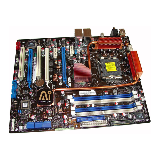
Page 30: Motherboard Layout
SPDIF_O1 1394a LAN1_USB12 LAN2_USB34 CHA_FAN1 Audio slot OPT_FAN2 Marvell 88E1116 PCIEX1 Marvell 88E1116 P5N32-E SLI Plus OPT_FAN1 SPDIF_O2 IE1394_2 Refer to 2.8 Connectors for more information about rear panel connectors and internal connectors. 24.5cm (9.6in) LGA775 ® NVIDIA ® NFORCE dual x 16 SLI ®... -
Page 31: Layout Contents
PS/2 keyboard port (purple) Supreme FX Line In port (light blue) Line Out port (lime) Microphone port (pink) Center/Subwoofer port (orange) Side Speaker Out port (gray) Rear Speaker Out port (black) ASUS P5N32-E SLI Plus Page 2-15 2-20 2-20 2-20 Page 2-21... - Page 32 System power LED (2-pin PLED) • Hard disk drive activity LED (2-pin IDE_LED) • System warning speaker (4-pin SPEAKER) • ATX power button/soft-off button (2-pin PWR) • Reset button (2-pin RESET) ASUS Q-connector (system panel) Page 2-26 2-26 2-27 2-28 2-29 2-30 2-31...
-
Page 33: Central Processing Unit (Cpu)
ASUS will shoulder the cost of repair only if the damage is shipment/transit-related. • Keep the cap after installing the motherboard. ASUS will process Return Merchandise Authorization (RMA) requests only if the motherboard comes with the cap on the LGA775 socket. -
Page 34: Installing The Cpu
Locate the CPU socket on the motherboard. ® P5N32-E SLI Plus P5N32-E SLI Plus CPU Socket 775 Before installing the CPU, make sure that the socket box is facing towards you and the load lever is on your left. Press the load lever with your thumb (A), then move it to the left (B) until it is released from the retention tab. - Page 35 The motherboard supports Intel Memory 64 Technology (EM64T), Enhanced Intel SpeedStep (EIST), and Hyper-Threading Technology. Refer to the Appendix for more information on these CPU features. ASUS P5N32-E SLI Plus Load plate Alignment key CPU notch Gold triangle mark LGA775 processors with the Intel ®...
-
Page 36: Installing The Cpu Heatsink And Fan
2.3.2 Installing the CPU heatsink and fan The Intel LGA775 processor requires a specially designed heatsink and fan ® assembly to ensure optimum thermal condition and performance. • When you buy a boxed Intel and heatsink assembly. If you buy a CPU separately, make sure that you use only Intel •... - Page 37 Connect the CPU fan cable to the connector on the motherboard labeled CPU_FAN. ® P5N32-E SLI Plus P5N32-E SLI Plus CPU fan connector Do not forget to connect the CPU fan connector! Hardware monitoring errors can occur if you fail to plug this connector. ASUS P5N32-E SLI Plus...
- Page 38 To uninstall the CPU heatsink and fan: Disconnect the CPU fan cable from the connector on the motherboard. Rotate each fastener counterclockwise. Pull up two fasteners at a time in a diagonal sequence to disengage the heatsink and fan assembly from the motherboard.
- Page 39 (The photo shows the groove shaded for emphasis.) Refer to the documentation in the boxed or stand-alone CPU fan package for detailed information on CPU fan installation. ASUS P5N32-E SLI Plus Narrow end of the groove 2-13...
-
Page 40: Installing The Optional Fan
2.3.4 Installing the optional fan Install the optional fan only if you are using a passive cooler or a water cooler. Installing the optional fan with an active CPU cooler will interfere with the airflow and destabilize the system. Position the fan above the pipe and heatsink assembly. -
Page 41: System Memory
240-pin footprint compared to the 184-pin DDR DIMM. DDR2 DIMMs are notched differently to prevent installation on a DDR DIMM socket. The figure illustrates the location of the DDR2 DIMM sockets: ® P5N32-E SLI Plus P5N32-E SLI Plus 240-pin DDR2 DIMM sockets Channel Channel A DIMM_A1 and DIMM_A2 Channel B... -
Page 42: Memory Configurations
• Always install DIMMs with the same CAS latency. For optimum compatibility, we recommend that you obtain memory modules from the same vendor. Visit the ASUS website at www.asus.com for the latest DDR2 Qualified Vendors List. • Due to chipset resource allocation, the system may detect less than 8 GB system memory when you installed four 2 GB DDR2 memory modules. -
Page 43: Installing A Dimm
Support the DIMM lightly with your fingers when pressing the retaining clips. The DIMM might get damaged when it flips out with extra force. Remove the DIMM from the socket. ASUS P5N32-E SLI Plus DDR2 DIMM notch Unlocked retaining clip DDR2 DIMM notch 2-17... -
Page 44: Expansion Slots
Expansion slots In the future, you may need to install expansion cards. The following sub-sections describe the slots and the expansion cards that they support. Make sure to unplug the power cord before adding or removing expansion cards. Failure to do so may cause you physical injury and damage motherboard components. -
Page 45: Interrupt Assignments
PCIEx1_1 PCI Slot_1 shared PCI Slot_2 USB 1.1 USB 2.0 LAN_1 LAN_2 PATA shared SATA_1 SATA_2 SATA_3 SATA_RAID 1394 Audio ASUS P5N32-E SLI Plus – – – – shared – – – – – – – – shared – –... -
Page 46: Pci Slots
2.5.4 PCI slots The PCI slots support cards such as a LAN card, SCSI card, USB card, and other cards that comply with PCI specifications. Refer to the figure below for the location of the slots. 2.5.5 PCI Express x1 slot This motherboard supports PCI Express x1 network cards, SCSI cards and other cards that comply with the PCI Express specifications. -
Page 47: Clear Rtc Ram (Clrtc)
Hold down the <Del> key during the boot process and enter BIOS setup to re-enter data. ® P5N32-E SLI Plus P5N32-E SLI Plus Clear RTC RAM • Make sure to re-enter your previous BIOS settings after you clear the CMOS. -
Page 48: Audio Card Installation
Audio card installation Take out the Audio card from the package. Locate the slot on the motherboard. Align the card connector with the slot and press firmly until the card sits on the slot completely. The above photo shows the audio card installed on the motherboard. -
Page 49: Connectors
LAN port LED indications. 32-bit OS LAN port LED indications Activity/Link Speed LED YELLOW* YELLOW* ORANGE * Blinking ASUS P5N32-E SLI Plus Description Soft-off Mode During Power ON/OFF 100 Mbps connection ACTIVITY/ SPEED LINK LED LAN port... - Page 50 64-bit OS LAN port LED indications Activity/Link Line In port (light blue). This port connects the tape, CD, DVD player, or other audio sources. Line Out port (lime). This port connects a headphone or a speaker. In 4-channel, 6-channel, and 8-channel configuration, the function of this port becomes Front Speaker Out.
- Page 51 PCs, or portable devices. 13. Optical S/PDIF Out port. This port connects an external audio output device via an optical S/PDIF cable. 14. PS/2 keyboard port (purple). This port is for a PS/2 keyboard. ASUS P5N32-E SLI Plus 2-25...
-
Page 52: Internal Connectors
FDD cable with a covered Pin 5. ® P5N32-E SLI Plus P5N32-E SLI Plus Floppy disk drive connector IDE connector (40-1 pin PRI_IDE) The onboard IDE connector is for the Ultra DMA 133/100/66 signal cable. There are three connectors on each Ultra DMA 133/100/66 signal cable: blue, black, and gray. - Page 53 ® P5N32-E SLI Plus P5N32-E SLI Plus IDE connector Serial ATA connectors (7-pin SATA1-6) These connectors are for the Serial ATA signal cables for Serial ATA hard disk drives. If you installed Serial ATA hard disk drives, you can create a RAID 0, RAID 1, RAID 0+1, RAID 5, or JBOD configuration with the onboard NVIDIA MediaShield™...
- Page 54 P5N32-E SLI Plus USB 2.0 connectors Never connect a 1394 cable to the USB connectors. Doing so will damage the motherboard! You can connect the USB cable to ASUS Q-Connector (USB, blue) first, and then install the Q-Connector (USB) to the USB connector onboard. 2-28...
- Page 55 Never connect a USB cable to the IEEE 1394a connector. Doing so will damage the motherboard! You can connect the 1394 cable to ASUS Q-Connector (1394, red) first, and then install the Q-Connector (1394) to the 1394 connector onboard. ASUS P5N32-E SLI Plus...
- Page 56 ® P5N32-E SLI Plus P5N32-E SLI Plus Fan connectors • Only the CHA_FAN1 and OPT_FAN 1~3 connectors support the ASUS Q-FAN 2 feature. • If you install two VGA cards, we recommend that you plug the rear chassis fan cable to the motherboard connector labeled OPT_FAN1 or OPT_FAN2 for better themal environment.
-
Page 57: Atx Power Connectors
Remove the jumper caps only when you intend to use the chassis intrusion detection feature. ® P5N32-E SLI Plus P5N32-E SLI Plus Chassis intrusion connector ATX power connectors (24-pin EATXPWR, 2 x 4-pin ATX12V) These connectors are for ATX power supply plugs. The power supply plugs are designed to fit these connectors in only one orientation. - Page 58 • For a fully configured system, we recommend that you use a power supply unit (PSU) that complies with ATX 12 V Specification 2.0 (or later version) and provides a minimum power of 550 W. • Do not forget to connect the 4-pin/8pin EATX12V power plug; otherwise, the system will not boot.
- Page 59 Connect the S/PDIF Out module cable to this connector, then install the module to a slot opening at the back of the system chassis. ® P5N32-E SLI Plus P5N32-E SLI Plus SPDIF OUT connector The S/PDIF module is purchased separately. ASUS P5N32-E SLI Plus SPDIF_O2...
-
Page 60: System Panel Connector
10. System panel connector (20-8 pin PANEL) This connector supports several chassis-mounted functions. ® P5N32-E SLI Plus P5N32-E SLI Plus System panel connector • System power LED (2-pin PLED) This 2-pin connector is for the system power LED. Connect the chassis power LED cable to this connector. -
Page 61: Asus Q-Connector
ASUS Q-Connector (system panel) You can use the ASUS Q-Connector to connect/disconnect chassis front panel cables in a few steps. Refer to the instructions below to install the ASUS Q- Connector. Connect the front panel cables to the ASUS Q-Connector. - Page 62 2-36 Chapter 2: Hardware information...
-
Page 63: Chapter 3: Powering Up
This chapter describes the power up sequence, the vocal POST messages, and ways of shutting down the system. Powering up... - Page 64 Chapter summary Starting up for the first time ... 3-1 Turning off the computer ... 3-2 ASUS P5N32-E SLI Plus...
-
Page 65: Starting Up For The First Time
Check the jumper settings and connections or call your retailer for assistance. At power on, hold down the <Delete> key to enter the BIOS Setup. Follow the instructions in Chapter 4. ASUS P5N32-E SLI Plus P5N32-E SLI Plus... -
Page 66: Turning Off The Computer
Turning off the computer 3.2.1 Using the OS shut down function If you are using Windows Click the Start button then click Shut Down... Make sure that the Shut Down option button is selected, then click the OK button to shut down the computer. The power supply should turn off after Windows If you are using Windows Click the Start button then select Turn Off Computer. -
Page 67: Chapter 4: Bios Setup
This chapter tells how to change the system settings through the BIOS Setup menus. Detailed descriptions of the BIOS parameters are also provided. BIOS setup... - Page 68 Managing and updating your BIOS ... 4-1 BIOS setup program ... 4-9 Main menu ... 4-13 Extreme Tweaker menu ... 4-18 Advanced menu ... 4-25 Power menu ... 4-30 Boot menu ... 4-36 Tools menu ... 4-41 Exit menu ... 4-45 ASUS P5N32-E SLI Plus...
-
Page 69: Managing And Updating Your Bios
Input/Output System (BIOS) setup. ASUS Update (Updates the BIOS in Windows ASUS EZ Flash 2 (Updates the BIOS in DOS using a floppy disk or a USB flash disk.) Award BIOS Flash Utility (Updates the BIOS in DOS mode using a bootable floppy disk.) - Page 70 Updating the BIOS through the Internet To update the BIOS through the Internet: Launch the ASUS Update utility from the Windows > Programs > ASUS > ASUSUpdate > ASUSUpdate. The ASUS Update main window appears. Select Update BIOS from the Internet option from the drop-down menu, then click Next.
- Page 71 Updating the BIOS through a BIOS file To update the BIOS through a BIOS file: Launch the ASUS Update utility from the Windows > Programs > ASUS > ASUSUpdate > ASUSUpdate. The ASUS Update main window appears. Select Update BIOS from a file option from the drop-down menu, then click Next.
-
Page 72: Creating A Bootable Floppy Disk
4.1.2 Creating a bootable floppy disk Do either one of the following to create a bootable floppy disk. DOS environment a. Insert a 1.44MB floppy disk into the drive. b. At the DOS prompt, type format A:/S then press <Enter>. Windows XP environment ®... -
Page 73: Asus Ez Flash 2 Utility
4.1.3 ASUS EZ Flash 2 utility The ASUS EZ Flash 2 feature allows you to update the BIOS without having to go through the long process of booting from a floppy disk and using a DOS-based utility. The EZ Flash utility is built-in the BIOS chip so it is accessible by pressing <Alt>... -
Page 74: Updating The Bios
Flash Utility. Follow these instructions to update the BIOS using this utility. Download the latest BIOS file from the ASUS web site. Rename the file to P5N32-EP.BIN and save it to a floppy disk, CD ROM or a USB flash disk in FAT 16/12 format. - Page 75 Remove the disk then press <F1> to restart the system. ASUS P5N32-E SLI Plus AwardBIOS Flash Utility for ASUS V1.14 (C) Phoenix Technologies Ltd. All Rights Reserved For NV Dual x16 SLI-P5N32-EP Flash Type - PMC Pm49FL004T LPC/FWH File Name to Program: P5N32-EP.bin...
-
Page 76: Saving The Current Bios File
The utility saves the current BIOS file to the floppy disk, then returns to the BIOS flashing process. AwardBIOS Flash Utility for ASUS V1.14 (C) Phoenix Technologies Ltd. All Rights Reserved For NV Dual x16 SLI-P5N32-EP Flash Type - PMC Pm49FL004T LPC/FWH File Name to Program: 0112.bin... -
Page 77: Bios Setup Program
The BIOS setup screens shown in this section are for reference purposes only, and may not exactly match what you see on your screen. • Visit the ASUS website (www.asus.com) to download the latest BIOS file for this motherboard. ASUS P5N32-E SLI Plus... -
Page 78: Bios Menu Screen
• The BIOS setup screens shown in this chapter are for reference purposes only, and may not exactly match what you see on your screen. • Visit the ASUS website (www.asus.com) to download the latest BIOS information. 4-10 Configuration fields... -
Page 79: Legend Bar
A configurable field is enclosed in brackets, and is highlighted when selected. To change the value of a field, select it then press <Enter> to display a list of options. Refer to “4.2.7 Pop-up window.” ASUS P5N32-E SLI Plus Function Displays the General Help screen... -
Page 80: Pop-Up Window
Phoenix-Award BIOS CMOS Setup Utility Advanced Power Boot 15 : 30 : 36 Thu, Apr 6 2006 [English] [1.44M, 3.5 in.] Legacy Diskette A: [ST321122A] [ASUS CDS520/A] Disabled ... [ ] [None] [None] [None] 720K , 3.5 in..[ ] [None] [None] [None] 1.44M, 3.5 in. -
Page 81: Main Menu
[English] [French] [Deutsch] [Chinese (Trad.)] [Chinese (Simp.)] [Japanese] 4.3.4 Legacy Diskette A [1.44M, 3.5 in.] Sets the type of floppy drive installed. Configuration options: [Disabled] [720K , 3.5 in.] [1.44M, 3.5 in.] ASUS P5N32-E SLI Plus Advanced Power Boot Tools 15 : 30 : 36... -
Page 82: Primary Ide Master/Slave
4.3.5 Primary IDE Master/Slave While entering Setup, the BIOS automatically detects the presence of IDE devices. There is a separate sub-menu for each IDE device. Select a device item then press <Enter> to display the IDE device information. Main PIO Mode UDMA Mode Primary IDE Master Access Mode... - Page 83 FDISK, to partition and format new IDE hard disk drives. This is necessary so that you can write or read data from the hard disk. Make sure to set the partition of the Primary IDE hard disk drives to active. ASUS P5N32-E SLI Plus 4-15...
- Page 84 4.3.6 SATA1/2/3/4/5/6 While entering Setup, the BIOS automatically detects the presence of Serial ATA devices. There is a separate sub-menu for each SATA device. Select a device item then press <Enter> to display the SATA device information. Main Extended IDE Drive Access Mode Capacity Cylinder...
-
Page 85: Hdd Smart Monitoring
Allows you to enable or disable the HDD Self-Monitoring Analysis and Reporting Technology (SMART) feature. Configuration options: [Disabled] [Enabled] 4.3.8 Installed Memory [xxx MB] Shows the size of installed memory. 4.3.9 Usable Memory [XXX MB] Shows the size of usable memory. ASUS P5N32-E SLI Plus 4-17... -
Page 86: Extreme Tweaker Menu
Loads the optimal settings for the system. Loads the standard settings for the system. Loads overclocking profiles with optimal parameters for stability when overclocking. The ASUS Non-delay Overclocking System feature intelligently determines the system load and automatically boosts the performance for the most demanding tasks. Exit... -
Page 87: System Clocks
Allows you to set the PCIEX16_3 overclocking frequency. Configuration options: [100 MHz]~[200 MHz] SPP <-> MCP Ref Clock, MHz [Auto] Configuration options: [Auto] [200.0 MHz] [200.5 MHz] [201.0 MHz] [201.5 MHz]~[500.0 MHz] ASUS P5N32-E SLI Plus [100] [100] [100] [Auto]... - Page 88 FSB & Memory Config This sub-menu allows you to adjust the system frequency-related items. Select an item, then press <Enter> to edit. Extreme Tweaker FSB & Memory Config FSB - Memory Clock Mode FSB - Memory Ratio FSB (QDR), MHz Actual FSB (QDR), MHz MEM (DDR), MHz Actual MEM (DDR), MHz...
-
Page 89: Overclocking
Configuration options: [Auto] [1] [2] [3] [4] [5] [6] [7] tRP [Auto] Configuration options: [Auto] [1] [2] [3] [4] [5] [6] [7] tRAS [Auto] Configuration options: [Auto] [1] [2] [3] [4] [5] [6] [7]...[31] ASUS P5N32-E SLI Plus [17] [Disabled] [Auto] 12 X 1.2000V... -
Page 90: Spread Spectrum Control
Command Per Clock (CMD) [Auto] Configuration options: [Auto] [1 clock] [2 clock] tRRD [Auto] Configuration options: [Auto] [1] [2] [3] [4] [5] [6] [7]...[15] tRC [Auto] Configuration options: [Auto] [1] [2] [3] [4] [5] [6] [7]...[31] tWR [Auto] Configuration options: [Auto] [1] [2] [3] [4] [5] [6] [7] tWTR [Auto] Configuration options: [Auto] [1] [2] [3] [4] [5] [6] [7]...[15] tREF [Auto]... -
Page 91: Over Voltage
DDR2 Channel B Ref Voltage VCore Voltage [Auto] Configuration options: [Auto] [1.90000V] [1.89375V] [1.88750V] [1.88125V] [1.87500V]...[0.83750V] [0.83125V] Memory Voltage [Auto] Configuration options: [Auto] [1.850V] [1.875V] [1.900V]...[3.400V] [3.425V] ASUS P5N32-E SLI Plus [Auto] Item Specific Help [Auto] [Auto] Set CPU VID to desired... -
Page 92: Nvidia Gpu Ex
1.2V HT Voltage [Auto] Configuration options: [Auto] [1.20V] [1.25V] [1.30V]...[1.90V] [1.95V] NB Core Voltage [Auto] Configuration options: [Auto] [1.20V] [1.25V] [1.30V]...[2.70V] [2.75V] SB Core Voltage [Auto] Configuration options: [Auto] [1.50V] [1.55V] [1.60V] [1.65V] [1.70V] [1.75V] [1.80V] [1.85V] CPU VTT Voltage [Auto] Configuration options: [Auto] [1.20V] [1.25V] [1.30V] [1.35V]...[1.50V] [1.55V] DDRII Controller Ref Voltage [Auto] Configuration options: [Auto] [DDR2_Vol/2] [DDR2_Vol/2-30mv] [DDR2_... -
Page 93: Advanced Menu
ESC: Exit POST Check LAN Cable [Disabled] POST Check LAN2 Cable [Disabled] Enables or disables checking of the LAN/LAN2 cable during the Power-On Self-Test (POST). Configuration options: [Disabled] [Enabled] ASUS P5N32-E SLI Plus Power Boot Tools Exit Item Specific Help Press [Enter] to set. -
Page 94: Pcipnp
4.5.2 PCIPnP Plug & Play O/S Primary Display Adapter Plug & Play O/S [No] When set to [No], the BIOS configures all the devices in the system. When set to [Yes] and if you install a Plug and Play operating system, the operating system configures the Plug and Play devices not required for boot. -
Page 95: Onboard Device Configuration
Allows you to enable or disable the IDE DMA transfer access. Configuration options: [Disabled] [Enabled] IDE Prefetch Mode [Enabled] Allows you to enable or disable the IDE PIO read prefetch mode. Configuration options: [Disabled] [Enabled] ASUS P5N32-E SLI Plus Advanced [Auto] [Auto] [AC97]... - Page 96 Serial-ATA Configuration This sub-menu allows you to change Serial ATA settings. Select an item then press <Enter> to edit. Serial-ATA Configuration Serial-ATA Controller RAID Enabled SATA1 SATA2 SATA3 SATA4 SATA5 SATA6 Serial-ATA Controller [Enabled] Allows you to enable or disable the onboard Serial ATA controller. Configuration options: [Disabled] [Enabled] RAID Enabled [Disabled] Enables or disables the onboard RAID controller.
-
Page 97: Usb Configuration
Allows you to enable or disable the USB 2.0 controller. Configuration options: [Disabled] [Enabled] USB Legacy Support [Enabled] Allows you to enable or disable support for USB devices on legacy operating systems (OS). Configuration options: [Disabled] [Enabled] ASUS P5N32-E SLI Plus [Enabled] Item Specific Help [Enabled] [Enabled] Enable or disable the USB 1.1 and 2.0... -
Page 98: Power Menu
Power menu The Power menu items allow you to change the settings for the Advanced Configuration and Power Interface (ACPI) and the Advanced Power Management (APM). Select an item then press <Enter> to display the configuration options. Main Extreme Tweaker ACPI Suspend Type ACPI APIC support APM Configuration... -
Page 99: Apm Configuration
USB Resume from S5 [Disabled] Allows you to enable or disable the support of USB keyboard or mouse resumption from S5. Configuration options: [Disabled] [Enabled] ASUS P5N32-E SLI Plus [Power-Off] Item Specific Help [Instant-Off]... - Page 100 Restore on AC Power Loss [Power-Off] Allows you to enable or disable the Restore on AC Power Loss function. Configuration options: [Power-Off] [Power-On] PWR Button < 4 secs [Instant-Off] Allows you to set the event after the power button is pressed for more than 4 seconds.
-
Page 101: Hardware Monitor
VTT CPU / DDR2 Termination /DDR2 Voltage +1.4V / DDR2 Voltage The onboard hardware monitor automatically detects the voltage output through the onboard voltage regulators. ASUS P5N32-E SLI Plus Item Specific Help Press [Enter] to go to the sub-menu. [600 RPM]... - Page 102 Temperature Monitor Power Temperature Monitor CPU Temperature M/B Temperature CPU, M/B Temperature The onboard hardware monitor automatically detects and displays the motherboard and CPU temperatures. These items are not user-configurable. Fan Speed Monitor Power Fan Speed Monitor CPU Fan Speed CHA_FAN1 Speed PWR FAN Speed CPU FAN / CHA _FAN1 Speed...
-
Page 103: Fan Speed Control
CPU fan speed is too low. If you set this item to [Disabled], the system will not warn you even if no fan is installed or if the fan is not functioning properly. Configuration options: [Disabled] [600 RPM] [1200 RPM] [1600 RPM] ASUS P5N32-E SLI Plus Item Specific Help [Duty Cycle Mode]... -
Page 104: Boot Menu
Boot menu The Boot menu items allow you to change the system boot options. Select an item then press <Enter> to display the sub-menu. Main Extreme Tweaker Boot Device Priority Removable Drives Hard Disk Drives CDROM Drives Boot Settings Configuration Security ↑↓... -
Page 105: Removable Drives
CDROM Drives Phoenix-Award BIOS CMOS Setup Utility CDROM Drives 1. 1st Slave: XXXXXXXXX 1. 1st Slave: XXXXXXXXX Allows you to assign optical drives attached to the system. ASUS P5N32-E SLI Plus Boot Boot Boot Select Menu Item Specific Help Select Menu... -
Page 106: Boot Settings Configuration
4.7.5 Boot Settings Configuration Boot Settings Configuration Case Open Warning Quick Boot Boot Up Floppy Seek Bootup Num-Lock Typematic Rate Setting Typematic Rate (Chars/Sec) Typematic Delay (Msec) OS Select For DRAM > 64MB Full Screen LOGO Halt On ↑↓ : Select Item F1:Help →←: Select Menu ESC: Exit... -
Page 107: Security
Full Screen LOGO [Enabled] Allows you to enable or disable the full screen logo display feature. Configuration options: [Disabled] [Enabled] Make sure that the above item is set to [Enabled] if you want to use the ASUS MyLogo3™ feature. Halt On [All Errors] Allows you to set the error report type. - Page 108 When prompted, confirm the password by typing the exact characters again, then press <Enter>. The password field setting is changed to Set. To clear the password: Select the password field and press <Enter> twice. The following message appears: PASSWORD DISABLED !!! Press any key to continue...
-
Page 109: Tools Menu
F1:Help →←: Select Menu ESC: Exit ASUS Music Alarm [Disabled] Allows you to enable or disable the ASUS Music Alarm function. Configuration options: [Disabled] [Enabled] The succeeding items become user-configurable when you enable the ASUS Music Alarm. Alarm Date: Sunday/Monday/Tuesday/Wednesday/Thursday/Friday/ Saturday [Enabled] Allows you to enable or disable the alarm for a particular day. - Page 110 Volume [16] Allows you to set the volume level of the music alarm. Configuration options: [01] ~ [32] 4.8.2 ASUS O.C. Profile This item allows you to store or load multiple BIOS settings. ASUS BIOS Profile Load BIOS Profile Save BIOS Profile...
- Page 111 Enter the BIOS setup program. Go to the “Tools” menu to select “Save to File.” Press <Enter> then the setup screen will appear. Press <Tab> to switch between the drives. Press hot-key <S> to save the file. ASUS P5N32-E SLI Plus Tools Select Menu Item Specific Help Save current BIOS Profile to Profile 1.
- Page 112 The BIOS file will be saved as “xxx.CMO“. 4.8.3 ASUS EZ Flash 2 Allows you to run ASUS EZ Flash 2. When you press <Enter>, a confirmation message appears. Use the left/right arrow key to select between [Yes] or [No], then press <Enter> to confirm your choice.
-
Page 113: Exit Menu
This option allows you to discard the selections you made and restore the previously saved values. After selecting this option, a confirmation appears. Select YES to discard any changes and load the previously saved values. ASUS P5N32-E SLI Plus Power Boot... - Page 114 4-46 Chapter 4: BIOS setup...
-
Page 115: Chapter 5: Software Support
This chapter describes the contents of the support CD that comes with the motherboard package. Software support... - Page 116 Chapter summary Installing an operating system ... 5-1 Support DVD information ... 5-1 Software information ... 5-9 RAID configurations ... 5-26 Creating a RAID driver disk ... 5-34 ASUS P5N32-E SLI Plus...
-
Page 117: Installing An Operating System
The contents of the Support DVD are subject to change at any time without notice. Visit the ASUS website(www.asus.com) for updates. 5.2.1 Running the Support DVD Place the Support DVD to the optical drive. The DVD automatically displays the Drivers menu if Autorun is enabled in your computer. -
Page 118: Drivers Menu
The drivers menu shows the available device drivers if the system detects installed devices. Install the necessary drivers to activate the devices. ASUS InstAll - Installation Wizard for Drivers Launches the ASUS InstAll driver installation wizard. Nvidia Chipset Driver Program... -
Page 119: Utilities Menu
The ASUS AI Booster application allows you to overclock the CPU speed in Windows environment. ® ASUS Music Alarm The ASUS Music Alarm is an audio alarm clock that uses your favorite CD music to give you a personal wake-up call. ASUS P5N32-E SLI Plus... - Page 120 Adobe Reader V7.0 Installs the Adobe Acrobat Reader that allows you to open, view, and print ® ® documents in Portable Document Format (PDF). Microsoft DirectX 9.0c Installs the Microsoft DirectX 9.0c driver. The Microsoft DirectX 9.0c is a ® ®...
-
Page 121: Make Disk Menu
The Make Disk menu contains items to create the NVIDIA® nForce™ dual x16 SLI SATA RAID driver disk. Make NVIDIA 32bit XP/2000/2003 SATA RAID Driver Make NVIDIA 64bit 2003 SATA RAID Driver Allows you to create an NVIDIA Serial ATA RAID driver disk for a 32-bit/64-bit ® system. ASUS P5N32-E SLI Plus... -
Page 122: Manuals Menu
5.2.6 ASUS Contact information Click the Contact tab to display the ASUS contact information. You can also find this information on the inside front cover of this user guide. Reader from the Utilities menu before opening a user manual ®... -
Page 123: Other Information
Support DVD. Click an icon to display the specified information. Motherboard Info Displays the general specifications of the motherboard. Browse this DVD Displays the Support DVD contents in graphical format. ASUS P5N32-E SLI Plus... -
Page 124: Technical Support Form
Technical support form Displays the ASUS Technical Support Request Form that you have to fill out when requesting technical support. Filelist Displays the contents of the Support DVD and a brief description of each in text format. Chapter 5: Software support... -
Page 125: Software Information
5.3.1 ASUS MyLogo3™ The ASUS MyLogo3™ utility lets you customize the boot logo. The boot logo is the image that appears on screen during the Power-On Self-Tests (POST). The ASUS MyLogo3™ is automatically installed when you install the ASUS Update utility from the Support DVD. - Page 126 Ratio box. When the screen returns to the ASUS Update utility, flash the original BIOS to load the new boot logo. 10. After flashing the BIOS, restart the computer to display the new boot logo during POST.
-
Page 127: Soundmax ® High Definition Audio Utility
If the SoundMAX audio utility is correctly installed, you ® will find the SoundMAX icon on the taskbar. ® ASUS P5N32-E SLI Plus High Definition Audio utility ® audio utility with AudioESP™ software to ® ® requires Microsoft Windows ®... -
Page 128: Audio Setup Wizard
From the taskbar, double-click on the SoundMAX icon to display the SoundMAX ® ® Control Panel. Audio Setup Wizard By clicking the icon from the SoundMAX control panel, you can easily ® configure your audio settings. Simply follow succeeding screen instructions and begin enjoying High Definition Audio. - Page 129 This screen helps you adjust microphone volume. You will be asked to read pre- written text to allow the AudioWizard to adjust the volume as you speak. ASUS P5N32-E SLI Plus Adjust speaker volume This screen helps you adjust speaker volume.
- Page 130 Audio preferences Click the icon to go to the Preferences page. This page allows you to change various audio settings. General options Click the General tab to choose your playback and recording devices, enable/ disable the AudioESP™ feature, and enable/disable digital output. This feature is consists of two elements: DTS interactive and DTS NEO:PC.
- Page 131 You can enable it when you have conference call to reduce echoes in the other side. The directional Array and Speaker Phone function only when working with the ASUS Array Mic. The ASUS Array Mic is purchased separately.
-
Page 132: Asus Pc Probe Ii
® To launch the PC Probe II from the Windows > ASUS > PC Probe II > PC Probe II v1.xx.xx. The PC Probe II main window appears. After launching the application, the PC Probe II icon appears in the Windows taskbar. - Page 133 When displayed, the monitor panel for that sensor also turns red. Refer to the Monitor panels section for details. Preferences You can customize the application using the Preference section in the main window. Click the box before each preference to activate or deactivate. ASUS P5N32-E SLI Plus Function 5-17...
- Page 134 Hardware monitor panels The hardware monitor panels display the current value of a system sensor such as fan rotation, CPU temperature, and voltages. The hardware monitor panels come in two display modes: hexagonal (large) and rectangular (small). When you check the Enable Monitoring Panel option from the Preference section, the monitor panels appear on your computer’s desktop.
- Page 135 DMI browser Click to display the DMI (Desktop Management Interface) browser. This browser displays various desktop and system information. Click the plus sign (+) before DMI Information to display the available information. ASUS P5N32-E SLI Plus Small display 5-19...
- Page 136 PCI browser Click to display the PCI (Peripheral Component Interconnect) browser. This browser provides information on the PCI devices installed on your system. Click the plus sign (+) before the PCI Information item to display available information. Usage The Usage browser displays real-time information on the CPU, hard disk drive space, and memory usage.
- Page 137 The Preference tab allows you to customize sensor alerts, or change the temperature scale. Loads the default threshold values for each sensor Applies your changes ASUS P5N32-E SLI Plus Loads your saved Cancels or configuration ignores your changes Saves your...
-
Page 138: Asus Music Alarm
This motherboard is equipped with an audio alarm clock called ASUS Music Alarm. The ASUS Music Alarm gives you a personal wake-up called with your favorite CD music when the system is off. The onboard audio CODEC supports this feature, which requires an optical drive (CD-ROM, CD-RW, or DVD-ROM). - Page 139 Click the Utilities tab and choose ASUS Music Alarm to install the utility. Insert an audio CD into the optical drive. Launch the ASUS Music Alarm application by going to Start > ASUS > ASUS Music Alarm. The main window appears.
-
Page 140: Adjusting The Volume
CD, the ASUS Music Alarm is automatically disabled/turned off. • While the music alarm is playing, the optical drive front panel functions are automatically disabled. • The ASUS Music Alarm works only when the system is off. 5-24 ) next to Options Chapter 5: Software support... -
Page 141: Asus Ai Booster
5.3.5 ASUS AI Booster The ASUS AI Booster application allows you to overclock the CPU speed in WIndows environment without the hassle of booting the BIOS. ® After installing the program from the bundled Support DVD, you can launch the utility by double-clicking the AI Booster icon on the Windows OS taskbar. -
Page 142: Raid Configurations
RAID configurations The motherboard comes with two RAID controllers that allow you to configure Serial ATA hard disk drives as RAID sets. • The NVIDIA nForce™ dual x16 SLI Southbridge includes a high ® performance SATA RAID controller that supports RAID 0, RAID 1, RAID 0+1, RAID 5 and JBOD for six independent Serial ATA channels. -
Page 143: Nvidia ® Raid Configurations
Device Configuration > Serial-ATA Configuration” for details. Select and enable the IDE or SATA drive(s) that you want to configure as RAID. See section “4.5.3 Onboard Device Configuration > Serial-ATA Configuration” for details. Save your changes and Exit Setup. ASUS P5N32-E SLI Plus 5-27... - Page 144 Make sure to re-enter your NVRAID settings after the CMOS is cleared; otherwise, the system will not recognize your RAID setup. • For detailed descriptions on the NVIDIA “NVIDIA • When using Windows Windows Entering the NVIDIA To enter the NVIDIA ®...
-
Page 145: Creating A Raid Volume
Press <Y> to clear the selected disks or <N> to proceed without clearing the disks. The following screen appears. Take caution in using this option. All data on the RAID drives will be lost! ASUS P5N32-E SLI Plus Mirroring Striping... -
Page 146: Rebuilding A Raid Array
[Ctrl-X]Exit A new set of navigation keys is displayed on the bottom of the screen. Press <Ctrl+X> to save settings and exit. Rebuilding a RAID array To rebuild a RAID array: From the Array List menu, use the up or down arrow keys to select a RAID array then press <Enter>. - Page 147 Press <Enter> to start rebuilding array or press <Esc> to cancel. After the rebuild process, the Array list menu appears. You will need to enter Window complete the rebuilt process. ASUS P5N32-E SLI Plus Array 1 : NVIDIA MIRROR XXX.XXG - Select Disk Inside Array -...
-
Page 148: Deleting A Raid Array
Deleting a RAID array To delete a RAID array: From the Array List menu, use the up or down arrow keys to select a RAID array then press <Enter>. The RAID Array details appear. RAID Mode: Mirroring Striping Width: 1 Adapt Channel [R] Rebuild... - Page 149 Press <C> to clear disk. The following confirmation message appears. Press <Y> to clear the disk data or press <N> to cancel. Take caution in using this option. All data on the RAID drives will be lost! ASUS P5N32-E SLI Plus Array 1 : NVIDIA MIRROR XXX.XXG...
-
Page 150: Creating A Raid Driver Disk
Creating a RAID driver disk A floppy disk with the RAID driver is required when installing Windows operating system on a hard disk drive that is included in a RAID set. To create a RAID driver disk: Place the motherboard support DVD into the DVD-ROM drive. Select Make Disk tab. -
Page 151: Nvidia
This chapter tells how to install SLI-ready PCI Express graphics cards. ® NVIDIA SLI™ technology support... - Page 152 Chapter summary Overview ... 6-1 Dual graphics cards setup ... 6-2 ASUS P5N32-E SLI Plus...
-
Page 153: Overview
The NVIDIA SLI technology supports Windows system only. • Visit the NVIDIA zone website (http://www.nzone.com) for the latest certified graphics card and supported 3D application list. ASUS P5N32-E SLI Plus ® SLI™ (Scalable Link Interface) technology ® XP™ 32-bit/64bit operating... -
Page 154: Dual Graphics Card Setup
Dual graphics card setup 6.2.1 Installing SLI-ready graphics cards Install only identical SLI-ready graphics cards that are NVIDIA Different types of graphics cards will not work together properly. To install the graphics cards: Prepare two graphics cards. Each graphics card should have goldfingers for the SLI connector. - Page 155 Insert the second graphics card into the other slot (PCIEX16_3). Make sure that the card is properly seated on the slot. If required, connect an auxiliary power source to the PCI Express graphics cards. ASUS P5N32-E SLI Plus...
- Page 156 Align and insert the SLI connector to the goldfingers on each graphics card. Make sure that the connector is firmly in place. When installing two VGA cards using a 20-pin ATX PSU with sufficient+12v capability, we recommend that you connect the auxillary power source from the power supply to the graphics card.
-
Page 157: Installing The Device Drivers
From the pop-up menu, select nView Desktop Manager then click nView Properties. From the nView Desktop Manager window, select the Desktop Management tab. Click Properties to display the Display Properties dialog box. ASUS P5N32-E SLI Plus ® NVIDIA Settings icon... - Page 158 From the Display Properties dialog box, select the Settings tab then click Advanced. Select the NVIDIA GeForce tab. Click the slider to display the following screen, then select the SLI multi-GPU item. Click the Enable SLI multi-GPU check box. Click OK when done. Slider Chapter 6: NVIDIA ®...