JVC RMP-2580U - Remote Controller For Color Domes Instructions Manual
Remote control unit
Hide thumbs
Also See for RMP-2580U - Remote Controller For Color Domes:
- Product overview and specifications (4 pages)
Table of Contents
Advertisement
Quick Links
R
REMOTE CONTROL UNIT
RM-P2580
INSTRUCTIONS
For Customer Use:
Enter below the Model No. and Serial
No. which is located on the body. Retain
this information for future reference.
Model No.
Serial No.
INTRODUCTION
BASIC OPERATIONS
APPLIED OPERATIONS
CONNECTIONS
MENU SCREEN SETUPS
OTHER
RM-P2580
SC96858-001
Advertisement
Table of Contents

Related Manuals for JVC RMP-2580U - Remote Controller For Color Domes


Summary of Contents for JVC RMP-2580U - Remote Controller For Color Domes
- Page 1 INTRODUCTION BASIC OPERATIONS APPLIED OPERATIONS REMOTE CONTROL UNIT CONNECTIONS RM-P2580 INSTRUCTIONS MENU SCREEN SETUPS OTHER For Customer Use: Enter below the Model No. and Serial No. which is located on the body. Retain this information for future reference. Model No. RM-P2580 Serial No.
-
Page 2: Safety Precautions
Information for USA CAUTION This device complies with Part 15 of the FCC Rules. RISK OF ELECTRIC SHOCK Changes or modifications not approved by JVC could void DO NOT OPEN the user's authority to operate the equipment. CAUTION : TO REDUCE THE RISK OF ELECTRIC SHOCK, DO NOT REMOVE COVER (OR BACK). -
Page 3: Table Of Contents
1. INTRODUCTION Thank you for purchasing the JVC RM-P2580. These instructions are for the RM-P2580U. CONTENTS 1. INTRODUCTION CONTENTS ............................3 FEATURES ............................4 ACCESSORIES ........................... 4 PRECAUTIONS FOR PROPER OPERATION ..................4 CONTROLS, CONNECTORS AND INDICATORS ................5 2. BASIC OPERATIONS CAMERA SELECTION ........................ -
Page 4: Features
1. INTRODUCTION FEATURES Presetting of up to 64 positions (including the home positions) each, for up to 8 combination cameras (TK-C675B). Built-in PAN, TILT and ZOOM control for up to 8 cameras. RS-485 connection system enables cascaded connection of cameras. Built-in sequential switcher. -
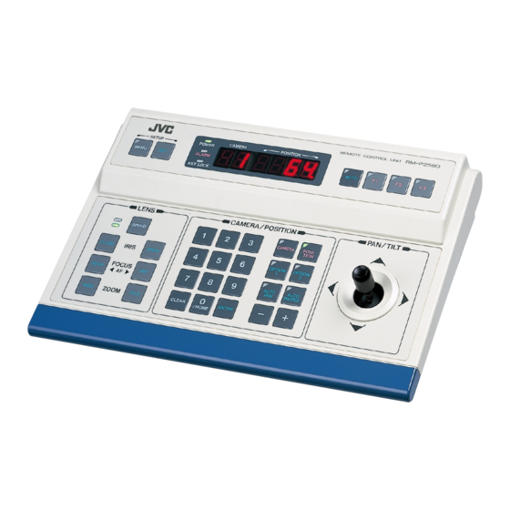
Page 5: Controls, Connectors And Indicators
1. INTRODUCTION CONTROLS, CONNECTORS AND INDICATORS [Control Panel] REMOTE CONTROL UNIT REMOTE CONTROL UNIT RM-P2580 RM-P2580 CAMERA CAMERA POSITION POSITION SETUP SETUP POWER ALARM MENU MENU AUTO AUTO KEY LOCK LENS LENS CAMERA/POSITION CAMERA/POSITION PAN/TILT PAN/TILT CAMERA CAMERA POSI- POSI- SPEED SPEED TION... - Page 6 Operate the lever to pan (swing horizontally) or tilt (swing volved in this control operation. vertically) the rotary turret of a camera. For details, please consult your dealer or JVC-authorized 8(Up) : Tilt the lever in this direction to tilt the rotary service agent.
- Page 7 1. INTRODUCTION CONTROLS, CONNECTORS AND INDICATORS (Continued) ⁄ [AUTO PATROL] button [FOCUS NEAR, FAR] FOCUS control buttons Press this button to switch the camera positions automati- Press and hold to control the FOCUS operation of the cam- cally in a preset order and at preset time intervals. era lens.
-
Page 8: Rear Panel
REF. :“REAR PANEL CONNECTORS (SERIAL-1, -2)” on ™ sponding to the VIDEO INPUT connector above it. page 23. Connect these connectors to a video device such as a Contact your JVC sales agent for details. monitor. · [SERIAL-2] External extension connector 2 ¢ DIP switch... -
Page 9: Basic Operations
2. BASIC OPERATIONS Manual Operation Camera Selection Position Selection ( REF. :Page 10) ( REF. : Page 11) Switching to the selected camera video. Switching the camera to the selected video position. CAMERA ENTER POSI- ENTER /HOME TION Pan/Tilt Operation Lens Operation ( REF. -
Page 10: Camera Selection
2. BASIC OPERATIONS CAMERA SELECTION Selecting a Desired Camera Press the CAMERA button so that the indicator lights up. Input the camera number using the numeric keys (0 to 9). The input figure is shown in the CAMERA display POSITION display CAMERA CAMERA display together with a period after it. -
Page 11: Position Selection
Otherwise the cameras cannot be moved to the desired positions. TK-C675BU: #0060 or after When the serial number of a camera is other than the above, please consult your nearest JVC-authorized service agent. Setting All Cameras to the Home Positions ( REF. -
Page 12: Manual Operation
2. BASIC OPERATIONS MANUAL OPERATION The manual operation allows you to PAN or TILT the selected camera and to control its lens. NOTES RM-P2580 RM-P2580 REMOTE CONTROL UNIT REMOTE CONTROL UNIT Manual operation is not available in the AUTO CAMERA CAMERA POSITION POSITION... -
Page 13: Auto Sequence Operation
2. BASIC OPERATIONS AUTO SEQUENCE OPERATION Operation with the Basic System ( REF. : Page 32 for the switching interval setting.) When the AUTO button is pressed, the AUTO indicator lights up and the MONITOR OUTPUT connectors output the camera images, switching them in order of camera numbers at constant intervals. -
Page 14: Auto Pan Operation
2. BASIC OPERATIONS AUTO PAN OPERATION The AUTO PAN operation consists of low-speed horizontal movement of a camera between preset positions at a constant time interval. Automatic panning is set between 2 points. This function can be set on individual cameras. Press the AUTO PAN button. -
Page 15: Auto Patrol Operation
2. BASIC OPERATIONS AUTO PATROL OPERATION The AUTO PATROL operation consists of high-speed camera movement between multiple pre-set positions, in a sequence and at time intervals set by the user. This function can be set on individual cameras. POSITION display Press the AUTO PATROL button. -
Page 16: Key Lock (Prevention Of Operation Mistake)
2. BASIC OPERATIONS KEY LOCK (PREVENTION OF OPERATION MISTAKE) The KEY LOCK function helps prevent operational mistakes by inhibiting the functions of all the buttons and the joystick on the control panel. KEY LOCK Press and hold the SET button for more than 3 seconds SET button indicator to put the unit into KEY LOCK status. -
Page 17: Applied Operations
3. APPLIED OPERATIONS ALARM OPERATION Alarm input signals can be applied to the DATA I/O terminals on the rear panel. The unit functions in either the ALARM PRIORITY mode or the MANUAL PRIORITY mode when an alarm signal is input. ( REF. : “CONTROL UNIT SCREEN”... -
Page 18: Data Output
Setting alterations are necessary according to which time-lapse VCR is connected. REF. : “CONTROL UNIT SCREEN” on page 28 and “DATA I/O screen: CAM SWITCH Item” on page 30 Set the CAM SWITCH to LOW when a time-lapse VCR of JVC is connected. NOTE To switch the Alarm signal correctly by the CAM SW signal, set it in the following manner: Make sure that video signals are input to VIDEO INPUT 1. -
Page 19: Connections
4. CONNECTIONS BASIC SYSTEM (A MODE) This system accepts video signals from the cameras via the VIDEO INPUT connectors. Up to 8 cameras can be connected in this system. Setting Procedure Connect all the equipment. (All the cameras must be synchronized). Set the system mode selection to A Mode, and set the rear DIP SW1 to "OFF". - Page 20 4. CONNECTIONS A MODE The master monitor displays the video signal from the selected camera. Use the CAMERA SW input to switch the video signal and record it on the VCR. The preset operation, manual operation, AUTO PAN operation and AUTO PATROL operation are available for each camera. When fixed cameras are used, only the video signal can be switched.
-
Page 21: Applied System (B Mode)
4. CONNECTIONS APPLIED SYSTEM (B MODE) <The compatible frame switchers are SW-D7000 and SW-D8000.> This system accepts the connection of up to 16 cameras. The video is recorded by means of a frame switcher. Setting Procedure When an alarm input is required to the SW-D7000/ SW-D8000, be sure to use the ALM OUTPUT of Connect all the equipment. - Page 22 4. CONNECTIONS B MODE The monitor displays the video that is switched by the frame switcher. The master monitor displays either a multi-split screen or the menu screen. The cameras are selected by controlling the frame switcher through the SERIAL-2 connector. The preset operation, manual operation, AUTO PAN operation and AUTO PATROL operation are individually available for each camera.
-
Page 23: Rear Panel Connectors
4. CONNECTIONS REAR PANEL CONNECTORS TO CAMERA Connection to control the camera. (The RM-P2580 is compatible with a TK-C675B camera.) Communication is carried out by MULTIDROP FULL DUPLEX (RS-485, FULL DUPLEX). RM-P2580 CAMERA 1 RX + RX - TX + TX - R X + T X +... - Page 24 Set “polarity” according to the VCR to be used. When using a JVC time-lapse VCR, set to “LOW”. REF. : “CONTROL UNIT SCREEN” on page 28 and “CAM SWITCH item of DATA I/O SCREEN” on page 30.
-
Page 25: Menu Screen Setups
5. MENU SCREEN SETUPS FLOW OF MENUS For details of each screen, please refer to the reference pages 26 to 28. SET UP screen POSITION SETUP POSITION SETUP screen ( REF. : Page 27) CAMERA CAMERA screen ( REF. : Page 28) CONTROL UNIT screen ( REF. -
Page 26: Menu Operation
5. MENU SCREEN SETUPS MENU OPERATION SET button PAN/TILT Set the POWER switch on the rear panel to “ON”. control lever MENU button Press and hold the MENU button for about 3 seconds. The LED indicator lights up and the MONITOR OUTPUT 1 connector on the rear panel outputs the SETUP screen RM-P2580 RM-P2580... -
Page 27: Setup Screen (Main Menu)
5. MENU SCREEN SETUPS POSITION SETUP SCREEN This screen is used to preset, correct or delete the camera positions. No position can be selected unless it has been preset. Up to 64 positions including the home position can be preset. Presetting and Correcting Camera Positions MENU button CAMERA button... -
Page 29: Option Screen
5. MENU SCREEN SETUPS ALARM SCREEN Item Function Options Default PRIORITY Sets whether an alarm input is accepted during manual opera- ALARM, ALARM tion. MANUAL ALARM : Alarm input is accepted even during manual opera- tion. ALARM MANUAL : Alarm input is not accepted during manual opera- PRIORITY ALARM ALARM TIME... -
Page 30: Data I/O Screen
• Are items ALARM TEXT and BUZZER TIME set to NONE? Page 31 played and/or buzzer does Page 32 not sound when an alarm signal is input. If the problem still cannot be solved after following the above checks, please consult your nearest authorised JVC service agent. -
Page 31: Specifications
6. OTHER SPECIFICATIONS Video lines Applicable cameras : TK-C675B Max. number of connected cameras : 8 (A mode), 16(B mode) Number of inputs : 8 (BNC) Max. cable length : 1.2 km Level : Composite, 1 V(p-p) Control terminals : Push terminals (RS-485) Number of outputs : 2 (BNC) 9600 bps. - Page 32 is a registered trademark owned by VICTOR COMPANY OF JAPAN, LTD. is a registered trademark in Japan, the U.S.A., the U.K. and many other countries. Printed in Japan © 1999 VICTOR COMPANY OF JAPAN, LIMITED SC96858-001...