Yamaha EF4000DE - Premium Generator Owner's Manual
Owners manual
Hide thumbs
Also See for EF4000DE - Premium Generator:
- Owner's manual (62 pages) ,
- Theory & diagnostics manual (218 pages)

Related Manuals for Yamaha EF4000DE - Premium Generator


Summary of Contents for Yamaha EF4000DE - Premium Generator
- Page 1 Generator OWNER’S MANUAL Read this manual carefully before operating this machine. EF4000DE EF4000D LIT-19626-01-75 7DA-F8199-12...
- Page 2 Read this manual carefully before operating this machine.This manual should stay with this machine if it is sold.
- Page 3 INTRODUCTION Congratulations on your purchase of your new Yamaha. This manual will provide you with a good basic understanding of the operation and maintenance of this machine. If you have any questions regarding the operation or maintenance of your machine, please consult a Yamaha dealer.
- Page 4 If there is any question concerning this manu- A TIP provides key information to make al, please consult a Yamaha dealer. procedures easier or clearer. 9 This manual should be considered a permanent part of this engine and should remain with this engine when resold.
-
Page 5: Table Of Contents
EF4000D ..........48 PREPARATION........12 BATTERY TRAY INSTALLATION..49 Fuel.............12 ENGINE HANGER INSTALLATION ..49 Engine oil..........13 OPTIONAL PARTS INSTALLATION..50 Battery installation ......14 YAMAHA MOTOR CORPORATION, PRE-OPERATION CHECK ....16 U.S.A. Pre-operation check ......16 EF SERIES GENERATORS OPERATION..........17 3-YEAR LIMITED WARRANTY....51 Starting the engine ......17 YAMAHA OUTDOOR POWER Stopping the engine......20... -
Page 6: Safety Information
AE00071 SAFETY INFORMATION 9 This generator is not designed for on-board use. Do not use it while installed on the vehicle. 9 Do not modify the generator or use it with its parts removed. 9 Do not allow children to operate the generator. 9 Be sure to carry the generator only by its carrying handle(s). -
Page 7: Fuel Is Highly Flammable And Poisonous
Fuel is highly flammable and poisonous 9 Always turn off the engine when refuelling. 9 Never refuel while smoking or in the vicinity of an open flame. 741-003 9 Take care not to spill any fuel on the engine or muffler when refuelling. -
Page 8: Electric Shock Prevention
9 Do not operate the engine with a dust cover or other objects covering it. 9 When covering the generator, be sure to do so only after the engine and muffler have completely cooled down. 7CC-001 Electric shock prevention 9 Never operate the engine in rain or snow. 741-010 9 Never touch the generator with wet hands or elec- trical shock will occur. -
Page 9: Connection Notes
Connection notes 9 Avoid connecting the generator to commercial power outlet. 9 Avoid connecting the generator in parallel with any other generator. 1 Correct 2 Incorrect Connection WARNING Before the generator can be connected to a build- ing’s electrical system, a licensed electrician must install an isolation (transfer) switch in the build- ing’s main fuse box. -
Page 10: Location Of Important Labels
EMISSION CONTROL INFORMATION The air index of this engine is 3 (California only) YAMAHA MOTOR POWERED PRODUCTS CO.,LTD. This engine meets 20** California exhaust and evaporative emission regulations for small off-road engines. THIS ENGINE MEETS U.S. EPA EXH EVP REGS FOR 20**. -
Page 11: Description
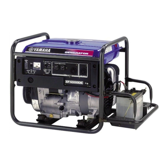
DESCRIPTION EF4000DE 1 Carrying handles (shaded) 2 Fuel tank cap 3 Engine hanger 4 Fuel level gauge 5 Fuel tank 6 Ground (earth) terminal 7 Battery 8 Oil filler cap 9 Oil drain bolt 0 Spark plug q Fuel cock w Recoil starter e Air filter case cover r Muffler... -
Page 12: Control Panel
Control panel (For EF4000DE) 3 4 5 1 Starter switch 2 Economy control switch 3 Engine switch 4 Oil warning light 5 Voltage meter 6 G.F.C.I. receptacle 7 AC switch (N.F.B.) 8 AC receptacle Control panel (For EF4000D) 1 Engine switch 2 Economy control switch 3 Oil warning light... -
Page 13: Control Function
CONTROL FUNCTION Engine switch The engine switch controls the ignition system. 7 “ON” Ignition circuit is switched on. The engine can be started. 2 5 “STOP” Ignition circuit is switched off. The engine will not run. 763-121 Oil warning light (red) When the oil level falls below the lower level, the oil warning light comes on and then the engine stops automatically. -
Page 14: Economy Control Switch
NOTICE Reduce the load to the specified generator rated output if the AC switch (N.F.B.) turns off. If it turns off again, consult a Yamaha dealer. Economy control switch 1 I “ON” When the economy control switch is turned “ON”, the economy control unit controls the engine speed according to the connected load. -
Page 15: G.f.c.i. Receptacle
G.F.C.I. receptacle WARNING TO REDUCE THE CHANCE OF ELECTRICAL SHOCK: 9 Do not attempt to operate electric devices if the ground fault circuit interrupter reset button 763-083 pops out repeatedly during use. 9 Test the ground fault circuit interrupter during the pre-operation checks according to the maintenance instructions on page 35. -
Page 16: Fuel Tank Cap
Fuel tank cap Remove the fuel tank cap by turning it counterclock- wise. 707-051a Fuel cock lever The fuel cock supplies fuel from the fuel tank to the carburetor. The fuel cock has two positions. 1 “ON” With the lever in this position, fuel flows to the carbure- 705-037i tor. -
Page 17: Preparation
Total: 7DF-020 23.0 L (6.08 US gal, 5.06 Imp gal) Your Yamaha engine has been designed to use regu- lar unleaded gasoline with a pump octane number ((R + M)/2) of 86 or higher, or research octane number of 91 or higher. -
Page 18: Engine Oil
Engine oil NOTICE The generator has been shipped without engine oil. Do not start the engine till fill with the suffi- cient engine oil. 700-068 1. Place the generator on a level surface. 2. Remove the oil filler cap. 1 Oil filler cap 3. -
Page 19: Battery Installation
Battery installation (For EF4000DE) (See page 33 and 38 for more details) WARNING 9 Electrolyte is poisonous and dangerous since it contains sulfuric acid, which causes severe burns. Avoid any contact with skin, eyes or clothing and always shield your eyes when working near batteries. - Page 20 WARNING 9 Be sure to service battery leads to prevent arc- ing when the battery is not installed. 9 Disconnect the battery charging output lead. Then insulate the generator side connector by folding it back on itself and carefully wrapping 762-004 it with electrical tape to prevent electrical con- tact with ground (earth) or any other leads.
-
Page 21: Pre-Operation Check
9 Check generator for oil leakage. Battery (See page 33) 9 Check the fluid level. 9 Add only distilled water if necessary. The point where abnormality was recognized by use. 9 Check operation. 9 If necessary, consult a Yamaha dealer. – 16 –... -
Page 22: Operation
OPERATION WARNING 9 Never operate the engine in a closed area or it may cause unconsciousness and death within a short time. Operate the engine in a well ven- tilated area. 9 Before starting the engine, do not connect any electric devices. - Page 23 2. Turn the fuel cock lever to “ON”. 1 “ON” 705-037 3. Turn the engine switch to “ON”. 1 7 “ON” 763-127a Electric starting model: (For EF4000DE) 4. Push the starter switch to start the engine. 1 Starter switch NOTICE 763-011a 9 Take your hand off the switch immediately after the engine starts.
- Page 24 Manual starting model: (For EF4000D) 4. Turn the choke lever to “1” . 1 Choke lever The choke is not required to start a warm engine. Turn 701-025c the choke lever to the original position. 5. Pull slowly on the recoil starter until it is engaged, then pull it briskly.
-
Page 25: Stopping The Engine
Stopping the engine Turn off any electric devices. 1. Turn the AC switch (N.F.B.) and economy control switch to “OFF”. 3 “OFF” å AC switch (N.F.B.) ∫ Economy control switch 763-126a 2. Disconnect any electric devices. 3. Turn the engine switch to “STOP”. 1 5 “STOP”... -
Page 26: Connection
Connection Alternating Current (AC) WARNING Be sure any electric devices are turned off before plugging it in. NOTICE 9 Be sure all electric devices including the lines and plug connections are in good condition before connection to the generator. 9 Be sure the total load is within generator rated output. - Page 27 NOTICE Reduce the load to the specified generator rated output if an AC switch turns off. If it turns off again, consult a Yamaha dealer. 240V 9 The 4-blade plug receptacle can supply both 120 V and 240 V power sources.
-
Page 28: Application Range
When using such equipment, consult with a Yamaha dealer. 9 When supplying precision equipment, electronic controllers, PCs, electronic computers, microcomputer-based equipment or battery chargers, keep the generator a sufficient distance away to prevent electrical interference from the engine. -
Page 29: Periodic Maintenance
WARNING If you are not familiar with maintenance work, have a Yamaha dealer do it for you. Maintenance chart WARNING Stop the engine before starting maintenance work. - Page 30 *1·····Initial replacement of the engine oil is after one month or 20 hours of operation. *2·····The air filter element needs to be replaced more frequently when using in unusually wet or dusty areas. ★····· Since these items require special tools, data and technical skills, have a Yamaha dealer perform the ser- vice.
-
Page 31: Spark Plug Inspection
5. Install the spark plug cap. Carburetor adjustment The carburetor is a vital part of the engine. Adjusting should be left to a Yamaha dealer with the profession- al knowledge, specialized data, and equipment to do so properly. – 26 –... -
Page 32: Engine Oil Replacement
Engine oil replacement WARNING Avoid draining the engine oil immediately after stopping the engine. The oil is hot and should be handled with care to avoid burns. 1. Place the generator on a level surface and warm up the engine for several minutes. Then stop the engine. -
Page 33: Air Filter
NOTICE Be sure no foreign material enters the crankcase. 7. Install the oil filler cap. Air filter 1. Remove the screws, and then remove the air filter case cover. 2. Remove the foam element. 1 Screws 2 Air filter case cover 3 Foam element 3. -
Page 34: Muffler Screen And Spark Arrester
Be sure the foam element sealing surface matches the air filter case so there is no air leak. 6. Install the air filter case cover and tighten the screws. Muffler screen and spark arrester WARNING The engine and muffler will be very hot after the engine has been run. - Page 35 5. Remove the carbon deposits on the muffler screen and spark arrester using a wire brush. NOTICE When cleaning, use the wire brush lightly to avoid damaging or scratching of the muffler screen and 711-022 spark arrester. 6. Check the muffler screen and spark arrester. Replace them if damaged.
-
Page 36: Fuel Cock
Fuel cock WARNING Never use the gasoline while smoking or in the vicinity of an open flame. 1. Stop the engine. 2. Turn the fuel cock lever to “OFF”. 3. Remove the fuel cock cup, gasket and fuel strain- 4. Clean the cup and fuel strainer with gasoline and wipe it off. -
Page 37: Fuel Tank Filter
Fuel tank filter WARNING Never use the gasoline while smoking or in the vicinity of an open flame. 1. Remove the fuel tank cap and fuel filter. 1 Fuel filter 2. Clean the fuel filter with gasoline. Replace it if damaged. 3. -
Page 38: Battery
Battery (For EF4000DE) Replenishing the battery fluid WARNING 9 Electrolyte is poisonous and dangerous since it contains sulfuric acid, which causes severe burns. Avoid any contact with skin, eyes or clothing and always shield your eyes when working near batteries. In case of contact, administer the following FIRST AID. -
Page 39: Recommended Battery
1. Remove the control panel screws and then remove the control panel. 1 Control panel screws 2. Replace the blown fuse with one of proper amper- age. Specified fuse: 20 A 7DA-021 If the fuse immediately blows again, consult a Yamaha dealer. 779-034b – 34 –... -
Page 40: G.f.c.i. Receptacle Test
Incorrect 4. If G.F.C.I. operation is correct, push in the reset button. If the G.F.C.I. operates incorrectly, consult a Yamaha dealer. WARNING Do not operate the generator with a faulty G.F.C.I. circuit. Electric shock could occur. Have the gen- erator repaired by a qualified mechanic. -
Page 41: Storage
STORAGE Long term storage of your generator will require some preventive procedures to guard against deterioration. Drain the fuel 1. Turn the engine switch to “STOP”. 5 “STOP” 2. Remove the fuel tank cap and the fuel filter. Extract the fuel from the fuel tank into an approved gasoline container using a commercially available hand siphon. -
Page 42: Engine
6. Drain the fuel remaining in the carburetor into an approved container by loosening the drain screw on the carburetor float chamber. 1 Drain screw 7. Tighten the drain screw. 7CC-016 8. Turn the engine switch to “STOP”. 9. Turn the fuel cock lever to “OFF”. 10. -
Page 43: Battery
Battery (For EF4000DE) 1. Remove the battery. NOTICE First, disconnect the negative battery lead, and then the positive battery lead. 762-003 2. Check the fluid level. Add only distilled water if necessary. (See page 33; “BATTERY Replenishing the battery fluid”) 3. - Page 44 — MEMO — – 39 –...
-
Page 45: Troubleshooting
Poor spark 2 Spark plug dirty with carbon or wet ..Remove carbon or wipe spark plug dry. 2 Faulty ignition system ..Consult a Yamaha deal- 791-001d Generator won’t produce power 2 Safety device (AC switch) to “OFF”····Turn the AC switch (N.F.B.) to “ON”. - Page 46 9 To prevent ELECTRIC SHOCK do not hold spark plug lead with hand while testing. Does not spark Clean Check the following Clogged 9 Fuel cock clogging replace Engine does not start. 9 Air cleaner element clogging. Consult a Yamaha dealer. – 41 –...
- Page 47 Faulty battery and/or starter motor. Consult a Yamaha dealer. Check engine oil level. Level low Consult a Add engine oil. Yamaha dealer. O Check the spark plug. 9 Type : BPR4ES 9 Gap : 0.7–0.8 mm (0.028–0.031 in) Incorrect Replace or Clean the spark adjust gap.
- Page 48 9 To prevent ELECTRIC SHOCK do not hold spark plug lead with hand while testing. Does not spark Clean Check the following O Clogged 9 Fuel line clogging replace Engine does not start. 9 Air cleaner element clogging. Consult a Yamaha dealer. – 43 –...
-
Page 49: Specifications
SPECIFICATIONS Dimensions Unit EF4000DE EF4000D Overall length mm (in) 894 (35.2) 670 (26.4) Overall width mm (in) 520 (20.5) 510 (20.1) Overall height mm (in) 577 (22.7) 577 (22.7) Dry weight kg (lb) 89 (196) 82 (181) Engine Unit EF4000DE/EF4000D Type Air cooled 4-stroke gasoline OHV Cylinder arrangement... -
Page 50: Consumer Information
PRI-I.D. NUMBER: Identification number records Record your Primary I.D., and serial num- bers in the spaces provided, to assist you MODEL in ordering spare parts from a Yamaha dealer. PRI-I.D. Also record and keep these I.D. numbers CODE SERIAL No. -
Page 51: Exhaust Emission Control System And Components
ROAD ENGINES. The acronyms conform to the latest version of the SAE’s recommended practice docu- ment J1930, “Diagnostic Acronyms, Terms, and Definitions For Electrical/Electronic System”. It is recommended that these items be serviced by a Yamaha dealer. – 46 –... -
Page 52: Wiring Diagram
WIRING DIAGRAM EF4000DE G Y L/W G Y L/W R/W B G/R G/R 1 Rotor assembly y Oil warning light Color code Black 2 Stator coil u Condenser 3 Main coil i Economy control unit Brown 4 Sub coil o Solenoid valve Green Gray 5 Voltage meter... -
Page 53: Ef4000D
EF4000D G Y L/W G Y L/W G/R G/R 1 Rotor assembly w Oil warning light Color code Black 2 Stator assembly e Condenser 3 Main coil r Economy control unit Brown 4 Sub coil t Solenoid valve Green Gray 5 Voltage meter y Economy control switch 6 AC switch (N.F.B.) -
Page 54: Battery Tray Installation
BATTERY TRAY INSTALLATION (For EF4000DE) ENGINE HANGER INSTALLATION – 49 –... -
Page 55: Optional Parts Installation
OPTIONAL PARTS INSTALLATION Two wheel kit – 50 –... -
Page 56: Yamaha Motor Corporation
Yamaha generator service dealer will, All 1995 and Later EF Models free of charge, repair or replace, at Yamaha’s Two (2) years from the original purchase date option, any part judged defective by Yamaha due to faulty workmanship or material from the factory. - Page 57 TIAL DAMAGES, SO THE ABOVE EXCLUSION MAY NOT APPLY TO YOU. THIS WARRANTY GIVES YOU SPECIFIC LEGAL RIGHTS, AND YOU MAY ALSO HAVE OTHER RIGHTS WHICH VARY FROM STATE TO STATE. YAMAHA MOTOR CORPORATION, U.S.A. Post Office Box 6555 Cypress, California 90630 – 52 –...
- Page 58 Yamaha Motor exactly as specified in the Owner’s Manual? Corporation, U.S.A. by the selling dealer at the A. No. The warranty on a new Yamaha cannot time of your purchase. If you should move after be “voided” or “cancelled.”...
-
Page 59: Yamaha Outdoor Power
If any evaporative emission- coverage, you should contact Yamaha Customer related part on your equipment is defective, the Relations at 1-800-962-7926. part will be repaired or replaced by Yamaha. YAMAHA MOTOR CORPORATION, USA Post Office Box 6555 Cypress, California 90630... -
Page 60: Yamaha Motor Corporation
Yamaha recommends that you retain all receipts covering maintenance on your SORE engine, but Yamaha cannot deny warranty solely for the lack of receipts or for your failure to ensure the performance of all scheduled maintenance. - Page 61 instructions required by subsection (d) must be warranted for the warranty period defined in Subsection (b)(2). If any such part fails during the period of warranty coverage, it must be repaired or replaced by the manufacturer according to Subsection (4) below. Any such part repaired or replaced under the warranty must be warranted for the remaining warranty period.
- Page 62 This work must be done at an authorized Yamaha dealer. Give notice to an authorized Yamaha dealer of any apparent defects(s) within a reasonable period of time after discovery. The SORE engine must be made available for inspection by an authorized Yamaha dealer.
- Page 63 This warranty does not cover damage resulting from accidents, acts of nature, or other events or occur- rences beyond the control of Yamaha. Yamaha Motor Corporation, U.S.A. expressly disclaims responsi- bility for any and all consequential damages, such as loss of time, inconvenience, loss or use of the SORE engine, or commercial loss.
-
Page 64: Yamaha Extended Service (Y.e.s.)
9 Y.E.S. is flexible. You can choose the plan that’s right for you: 12 months, 24 months or 36 months coverage. 9 Y.E.S. is administered by the same Yamaha people that handle your warranty - and it shows in the comprehensive coverage benefits. There are no hour limitations and Y.E.S. covers manufacturing defects just like your warranty. - Page 66 PRINTED IN CHINA 2011.02-0.1×1 ! PRINTED ON RECYCLED PAPER...