Intel DP55WB - Media Series P55 micro-ATX Core i7 i5 LGA1156 Desktop Motherboard Specification
Desktop board
Hide thumbs
Also See for DP55WB - Media Series P55 micro-ATX Core i7 i5 LGA1156 Desktop Motherboard:
- Product manual (80 pages)
Table of Contents
Advertisement
Quick Links
Intel® Desktop Board
DP55WB
Technical Product Specification
September 2009
Order Number: E70716-001US
®
The Intel
Desktop Board DP55WB may contain design defects or errors known as errata that may cause the product to deviate from published
specifications. Current characterized errata are documented in the Intel Desktop Board DP55WB Specification Update.
Advertisement
Table of Contents

Related Manuals for Intel DP55WB - Media Series P55 micro-ATX Core i7 i5 LGA1156 Desktop Motherboard


Summary of Contents for Intel DP55WB - Media Series P55 micro-ATX Core i7 i5 LGA1156 Desktop Motherboard
- Page 1 Order Number: E70716-001US ® The Intel Desktop Board DP55WB may contain design defects or errors known as errata that may cause the product to deviate from published specifications. Current characterized errata are documented in the Intel Desktop Board DP55WB Specification Update.
-
Page 2: Revision History
“undefined.” Intel reserves these for future definition and shall have no responsibility whatsoever for conflicts or incompatibilities arising from future changes to them. Intel desktop boards may contain design defects or errors known as errata, which may cause the product to deviate from published specifications. Current characterized errata are available on request. -
Page 3: Intended Audience
® Intended Audience The TPS is intended to provide detailed, technical information about the Intel Desktop Board DP55WB and its components to the vendors, system integrators, and other engineers and technicians who need this level of information. It is specifically not intended for general audiences. - Page 4 Intel Desktop Board DP55WB Technical Product Specification Other Common Notation Used after a signal name to identify an active-low signal (such as USBP0#) Gigabyte (1,073,741,824 bytes) GB/s Gigabytes per second Gb/s Gigabits per second Kilobyte (1024 bytes) Kbit Kilobit (1024 bits)
-
Page 5: Table Of Contents
1.3 Online Support................14 1.4 Processor ..................14 1.5 System Memory ................15 1.5.1 Memory Configurations ............16 ® 1.6 Intel P55 Express Chipset ............... 18 1.6.1 USB ................... 18 1.6.2 SATA Interfaces ..............19 1.7 Real-Time Clock Subsystem .............. 20 1.8 Audio Subsystem................ - Page 6 Intel Desktop Board DP55WB Technical Product Specification 2.5 Electrical Considerations ..............52 2.5.1 Power Supply Considerations ..........52 2.5.2 Fan Header Current Capability..........53 2.5.3 Add-in Board Considerations ..........53 2.6 Thermal Considerations ..............53 2.7 Reliability ..................56 2.8 Environmental ................56 3 Overview of BIOS Features 3.1 Introduction ...................
- Page 7 Connection Diagram for Front Panel Header ........45 Connection Diagram for Front Panel USB Headers ........ 47 Connection Diagram for Front Panel USB Header (with Intel Z-U130 USB Solid-State Drive, or Compatible Device, Support) ......47 Connection Diagram for IEEE 1394a Header ........48 Location of the Jumper Block.............
- Page 8 Intel Desktop Board DP55WB Technical Product Specification 26. Thermal Considerations for Components ..........55 27. Environmental Specifications............. 56 28. BIOS Setup Program Menu Bar............58 29. BIOS Setup Program Function Keys............ 58 30. Acceptable Drives/Media Types for BIOS Recovery ....... 61 31.
-
Page 9: Product Description
® Z-U130 USB Solid-State Drive (or compatible device) • Six internal Serial ATA (SATA) 3.0 Gb/s interfaces through Intel P55 Express Chipset with Intel Matrix Storage Technology RAID support • Two IEEE 1394a ports: ― One port via a back panel connector ―... - Page 10 Intel Desktop Board DP55WB Technical Product Specification Table 1. Feature Summary (continued) • One PCI Express 2.0 x16 bus add-in card connector Expansion Capabilities • Two PCI Express 2.0 x1 bus add-in card connectors • One PCI conventional bus connector •...
-
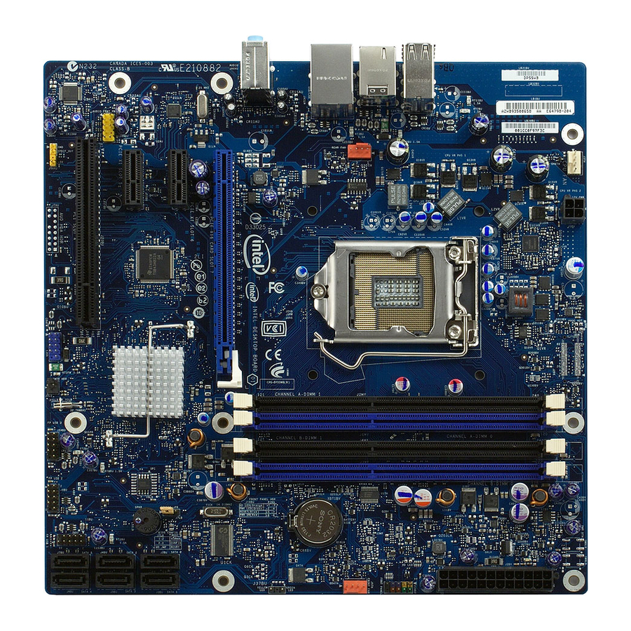
Page 11: Board Layout
Product Description 1.1.2 Board Layout Figure 1 shows the location of the major components on Intel Desktop Board DP55WB. Figure 1. Major Board Components... - Page 12 Intel Desktop Board DP55WB Technical Product Specification Table 2 lists the components identified in Figure 1. Table 2. Components Shown in Figure 1 Item/callout from Figure 1 Description PCI Conventional bus add-in card connector Front panel audio header PCI Express x1 bus add-in card connector...
-
Page 13: Block Diagram
Figure 2 is a block diagram of the major functional areas of the board. Figure 2. Block Diagram Legacy Considerations This board differs from other Intel Desktop Board products, with specific changes including (but not limited to) the following: •... -
Page 14: Online Support
Integration information http://www.intel.com/support/go/buildit Processor The board is designed to support the Intel Core i7 and Core i5 processors in an LGA1156 socket Other processors may be supported in the future. This board is designed to support processors with a maximum wattage of 95 W Thermal Design Power (TDP). The processors listed above are only supported when falling within the wattage requirements of the Intel Desktop Board DP55WB. -
Page 15: System Memory
2 Gbit 256 M x8/256 M x 8 Note: “DS” refers to double-sided memory modules (containing two rows of SDRAM) and “SS” refers to single-sided memory modules (containing one row of SDRAM). For information about… Refer to: Tested Memory http://support.intel.com/support/motherboards/desktop/sb/ CS-025414.htm... -
Page 16: Memory Configurations
Intel Desktop Board DP55WB Technical Product Specification 1.5.1 Memory Configurations The Intel Core i7 and Core i5 processors in the LGA1156 socket support the following types of memory organization: • Dual channel (Interleaved) mode. This mode offers the highest throughput for real world applications. -
Page 17: Memory Channel And Dimm Configuration
Figure 3 illustrates the memory channel and DIMM configuration. Figure 3. Memory Channel and DIMM Configuration NOTE The Intel P55 Express Chipset requires memory to be populated in the Channel A, DIMM 0 socket. For best memory performance always install memory into the blue DIMM memory... -
Page 18: Intel ® P55 Express Chipset
Interface (EHCI) host controllers that support USB high-speed signaling. High-speed USB 2.0 allows data transfers up to 480 Mb/s which is 40 times faster than full-speed USB. The Intel P55 Express Chipset provides the USB controller for all ports. The port arrangement is as follows: •... -
Page 19: Sata Interfaces
Product Description 1.6.2 SATA Interfaces The board provides six internal SATA connectors through the Intel P55 Express Chipset, which support one device per connector. The Intel P55 Express Chipset provides independent SATA ports with a theoretical maximum transfer rate of 3 Gb/s per port. One device can be installed on each port for a maximum of six SATA devices. -
Page 20: Real-Time Clock Subsystem
Figure 1 on page 11 shows the location of the battery. Audio Subsystem The board supports the Intel High Definition Audio subsystem based on the Realtek ALC888-VC2-GR audio codec. The audio subsystem supports the following features: •... -
Page 21: Audio Subsystem Software
Product Description 1.8.1 Audio Subsystem Software Audio software and drivers are available from Intel’s World Wide Web site. For information about Refer to Obtaining audio software and drivers Section 1.3, page 14 1.8.2 Audio Connectors and Headers The board contains audio connectors and headers on both the back panel and the component side of the board. -
Page 22: Lan Subsystem
LAN software and drivers http://downloadcenter.intel.com ® 1.9.1 Intel 82578DC Gigabit Ethernet Controller The Intel 82578DC Gigabit Ethernet Controller supports the following features: • 10/100/1000 BASE-T IEEE 802.3 compliant • PCI Express link • Compliant to IEEE 802.3x flow control support •... -
Page 23: Lan Subsystem Software
Product Description 1.9.2 LAN Subsystem Software LAN software and drivers are available from Intel’s World Wide Web site. For information about Refer to Obtaining LAN software and drivers http://downloadcenter.intel.com 1.9.3 RJ-45 LAN Connector with Integrated LEDs Two LEDs are built into the RJ-45 LAN connector (shown in Figure 5 below). -
Page 24: 1.10 Hardware Management Subsystem
Intel Desktop Board DP55WB Technical Product Specification 1.10 Hardware Management Subsystem The hardware management features enable the board to be compatible with the Wired for Management (WfM) specification. The board has several hardware management features, including the following: • Fan monitoring and control •... -
Page 25: Thermal Monitoring
Product Description 1.10.4 Thermal Monitoring Figure 6 shows the locations of the thermal sensors and fan headers. Item Description Rear chassis fan header Processor fan header Thermal diode, located on the processor die Hardware Monitoring ASIC Front chassis fan header Remote thermal diode Figure 6. -
Page 26: 1.11 Power Management
Intel Desktop Board DP55WB Technical Product Specification 1.11 Power Management Power management is implemented at several levels, including: • Software support through Advanced Configuration and Power Interface (ACPI) • Hardware support: ⎯ Power connector ⎯ Fan headers ⎯ LAN wake capabilities ⎯... -
Page 27: Power States And Targeted System Power
Product Description 1.11.1.1 System States and Power States Under ACPI, the operating system directs all system and device power state transitions. The operating system puts devices in and out of low-power states based on user preferences and knowledge of how devices are being used by applications. Devices that are not being used can be turned off. -
Page 28: Hardware Support
Intel Desktop Board DP55WB Technical Product Specification 1.11.1.2 Wake-up Devices and Events Table 8 lists the devices or specific events that can wake the computer from specific states. Table 8. Wake-up Devices and Events These devices/events can wake up the computer…... -
Page 29: Power Connector
Product Description 1.11.2.1 Power Connector ATX12V-compliant power supplies can turn off the system power through system control. When an ACPI-enabled system receives the correct command, the power supply removes all non-standby voltages. When resuming from an AC power failure, the computer returns to the power state it was in before power was interrupted (on or off). -
Page 30: Lan Wake Capabilities
Intel Desktop Board DP55WB Technical Product Specification 1.11.2.3 LAN Wake Capabilities CAUTION For LAN wake capabilities, the +5 V standby line for the power supply must be capable of providing adequate +5 V standby current. Failure to provide adequate standby current when implementing LAN wake capabilities can damage the power supply. -
Page 31: Wake From Usb
Product Description 1.11.2.5 Wake from USB USB bus activity wakes the computer from ACPI S1 or S3 states. NOTE Wake from USB requires the use of a USB peripheral that supports Wake from USB. 1.11.2.6 PME# Signal Wake-up Support When the PME# signal on the PCI Conventional bus is asserted, the computer wakes from an ACPI S1, S3, S4, or S5 state (with Wake on PME enabled in the BIOS). -
Page 32: Location Of The Standby Power Led
Intel Desktop Board DP55WB Technical Product Specification 1.11.2.8 +5 V Standby Power Indicator LED The +5 V standby power indicator LED shows that power is still present even when the computer appears to be off. Figure 7 shows the location of the standby power LED. -
Page 33: Energy Star*, E-Standby, And Erp Compliance
ENERGY STAR*, E-Standby, and ErP Compliance The US Department of Energy and the US Environmental Protection Agency have continually revised the ENERGY STAR requirements. Intel has worked directly with these two governmental agencies in the definition of new requirements. This Desktop Board meets the ENERGY STAR Program for Computers: Version 5.0 Category D... - Page 34 Intel Desktop Board DP55WB Technical Product Specification...
-
Page 35: Technical Reference
Technical Reference Memory Resources 2.1.1 Addressable Memory The board utilizes 16 GB of addressable system memory. Typically the address space that is allocated for PCI Conventional bus add-in cards, PCI Express configuration space, BIOS (SPI Flash device), and chipset overhead resides above the top of DRAM (total system memory). -
Page 36: Detailed System Memory Address Map
Intel Desktop Board DP55WB Technical Product Specification Figure 8. Detailed System Memory Address Map... -
Page 37: Memory Map
Technical Reference 2.1.2 Memory Map Table 9 lists the system memory map. Table 9. System Memory Map Address Range (decimal) Address Range (hex) Size Description 1024 K - 16777216 K 100000 - 3FFFFFFFF 16382 MB Extended memory 960 K - 1024 K F0000 - FFFFF 64 KB Runtime BIOS... -
Page 38: Back Panel Connectors
Intel Desktop Board DP55WB Technical Product Specification 2.2.1 Back Panel Connectors Figure 9 shows the location of the back panel connectors for the board. Item Description USB ports IEEE 1394a connector USB ports USB ports Line in Line out Mic in Figure 9. -
Page 39: Component-Side Connectors And Headers
Technical Reference 2.2.2 Component-side Connectors and Headers Figure 10 shows the locations of the component-side connectors and headers. Figure 10. Component-side Connectors and Headers... - Page 40 Intel Desktop Board DP55WB Technical Product Specification Table 10 lists the component-side connectors and headers identified in Figure 10. Table 10. Component-side Connectors and Headers Shown in Figure 10 Item/callout from Figure 10 Description PCI Conventional bus add-in card connector...
-
Page 41: Ieee 1394A Header
Data B (positive) Data B (negative) +12 V DC +12 V DC Key (no pin) Ground Table 12. Front Panel Audio Header for Intel HD Audio Signal Name Signal Name [Port 1] Left channel Ground [Port 1] Right channel PRESENCE# (Dongle present) -
Page 42: Sata Connectors
Intel Desktop Board DP55WB Technical Product Specification Table 29. Front Panel USB Header (with Intel Z-U130 USB Solid-State Drive, or Compatible Device, Support) Signal Name Signal Name +5 V DC +5 V DC Ground Ground KEY (no pin) LED# Table 14. SATA Connectors... -
Page 43: Processor Core Power Connector
Main power – a 2 x 12 connector. This connector is compatible with 2 x 10 connectors previously used on Intel Desktop boards. The board supports the use of ATX12V power supplies with either 2 x 10 or 2 x 12 main power cables. When... -
Page 44: Main Power Connector
Intel Desktop Board DP55WB Technical Product Specification Table 19. Main Power Connector Signal Name Signal Name +3.3 V +3.3 V +3.3 V -12 V Ground Ground +5 V PS-ON# (power supply remote on/off) Ground Ground +5 V Ground Ground Ground... -
Page 45: Connection Diagram For Front Panel Header
Technical Reference 2.2.2.4 Front Panel Header This section describes the functions of the front panel header. Table 20 lists the signal names of the front panel header. Figure 11 is a connection diagram for the front panel header. Table 20. Front Panel Header Signal Description Signal... -
Page 46: States For A One-Color Power Led
Intel Desktop Board DP55WB Technical Product Specification 2.2.2.4.2 Reset Switch Header Pins 5 and 7 can be connected to a momentary single pole, single throw (SPST) type switch that is normally open. When the switch is closed, the board resets and runs the POST. -
Page 47: Connection Diagram For Front Panel Usb Headers
Use only a front panel USB connector that conforms to the USB 2.0 specification for high-speed USB devices. Figure 12. Connection Diagram for Front Panel USB Headers Figure 13. Connection Diagram for Front Panel USB Header (with Intel Z-U130 USB Solid-State Drive, or Compatible Device, Support) -
Page 48: Connection Diagram For Ieee 1394A Header
Intel Desktop Board DP55WB Technical Product Specification 2.2.2.6 Front Panel IEEE 1394a Header Figure 14 is a connection diagram for the IEEE 1394a header. NOTE • The +12 V DC power on the IEEE 1394a header is fused. • The IEEE 1394a header provides one IEEE 1394a port. -
Page 49: Jumper Block
Technical Reference Jumper Block CAUTION Do not move the jumper with the power on. Always turn off the power and unplug the power cord from the computer before changing a jumper setting. Otherwise, the board could be damaged. Figure 15 shows the location of the jumper block. The 3-pin jumper block determines the BIOS Setup program’s mode. -
Page 50: Bios Setup Configuration Jumper Settings
Intel Desktop Board DP55WB Technical Product Specification Table 23. BIOS Setup Configuration Jumper Settings Function/Mode Jumper Setting Configuration Normal The BIOS uses current configuration information and passwords for booting. Configure After the POST runs, Setup runs automatically. The maintenance menu is displayed. -
Page 51: Mechanical Considerations
Technical Reference Mechanical Considerations 2.4.1 Form Factor The board is designed to fit into an ATX-form-factor chassis. Figure 16 illustrates the mechanical form factor for the board. Dimensions are given in inches [millimeters]. The outer dimensions are 9.60 inches by 9.60 inches [243.84 millimeters by 243.84 millimeters]. -
Page 52: Electrical Considerations
Intel Desktop Board DP55WB Technical Product Specification Electrical Considerations 2.5.1 Power Supply Considerations CAUTION The +5 V standby line from the power supply must be capable of providing adequate +5 V standby current. Failure to do so can damage the power supply. The total amount of standby current required depends on the wake devices supported and manufacturing options. -
Page 53: Fan Header Current Capability
Failure to ensure appropriate airflow may result in reduced performance of both the processor and/or voltage regulator or, in some instances, damage to the board. For a list of chassis that have been tested with Intel desktop boards please refer to the following website: http://www3.intel.com/cd/channel/reseller/asmo-na/eng/tech_reference/53211.htm... -
Page 54: Localized High Temperature Zones
Intel Desktop Board DP55WB Technical Product Specification CAUTION Ensure that the ambient temperature does not exceed the board’s maximum operating temperature. Failure to do so could cause components to exceed their maximum case temperature and malfunction. For information about the maximum operating temperature, see the environmental specifications in Section 2.8. -
Page 55: Thermal Considerations For Components
For processor case temperature, see processor datasheets and processor specification updates Intel P55 Express Chipset To ensure functionality and reliability, the component is specified for proper operation when Case Temperature is maintained at or below the maximum temperature listed in Table 26. -
Page 56: Reliability
Intel Desktop Board DP55WB Technical Product Specification Reliability The Mean Time Between Failures (MTBF) prediction is calculated using component and subassembly random failure rates. The calculation is based on the Bellcore Reliability Prediction Procedure, TR-NWT-000332, Issue 4, September 1991. The MTBF prediction is used to estimate repair rates and spare parts requirements. -
Page 57: Overview Of Bios Features
Overview of BIOS Features Introduction The board uses an Intel BIOS that is stored in the Serial Peripheral Interface Flash Memory (SPI Flash) and can be updated using a disk-based program. The SPI Flash contains the BIOS Setup program, POST, the PCI auto-configuration utility, LAN EEPROM information, and Plug and Play support. -
Page 58: Bios Flash Memory Organization
Intel Desktop Board DP55WB Technical Product Specification Table 28 lists the BIOS Setup program menu features. Table 28. BIOS Setup Program Menu Bar Maintenance Main Advanced Performance Security Power Boot Exit Clears Displays Configures Configures Sets Configures Selects Saves or... -
Page 59: System Management Bios (Smbios)
6. After the operating system loads the USB drivers, all legacy and non-legacy USB devices are recognized by the operating system, and Legacy USB support from the BIOS is no longer used. 7. Additional USB legacy feature options can be access by using Intel Integrator Toolkit. -
Page 60: Bios Updates
Intel Desktop Board DP55WB Technical Product Specification To install an operating system that supports USB, verify that Legacy USB support in the BIOS Setup program is set to Enabled and follow the operating system’s installation instructions. BIOS Updates The BIOS can be updated using either of the following utilities, which are available on the Intel World Wide Web site: ®... -
Page 61: Custom Splash Screen
The Intel Integrator’s Toolkit that is available from Intel can be used to create a custom splash screen. NOTE If you add a custom splash screen, it will share space with the Intel branded logo. Refer to For information about ®... -
Page 62: Boot Options
Intel Desktop Board DP55WB Technical Product Specification Boot Options In the BIOS Setup program, the user can choose to boot from a diskette drive, hard drive, USB drive, USB flash drive, CD-ROM, or the network. The default setting is for the diskette drive to be the first boot device, the hard drive second, and the ATAPI CD-ROM third. -
Page 63: Adjusting Boot Speed
It is possible to optimize the boot process to the point where the system boots so quickly that the Intel logo screen (or a custom logo splash screen) will not be seen. Monitors and hard disk drives with minimum initialization times can also contribute to a boot time that might be so fast that necessary logo screens and POST messages cannot be seen. -
Page 64: 3.10 Bios Security Features
Intel Desktop Board DP55WB Technical Product Specification 3.10 BIOS Security Features The BIOS includes security features that restrict access to the BIOS Setup program and who can boot the computer. A supervisor password and a user password can be set for the BIOS Setup program and for booting the computer, with the following restrictions: •... -
Page 65: 3.11 Bios Performance Features
Overview of BIOS Features 3.11 BIOS Performance Features The BIOS includes the following options to provide custom performance enhancements when using Intel Core i7 and Intel Core i5 processors in an LGA1156 socket. • Host Clock frequency adjustment • Processor multiplier adjustment (processor multiplier can only be adjusted down) •... - Page 66 Intel Desktop Board DP55WB Technical Product Specification...
-
Page 67: Error Messages And Beep Codes
Error Messages and Beep Codes Speaker The board-mounted speaker provides audible error code (beep code) information during POST. For information about Refer to The location of the onboard speaker Figure 1, page 11 BIOS Beep Codes Whenever a recoverable error occurs during POST, the BIOS causes the board’s speaker to beep an error message describing the problem (see Table 33). -
Page 68: Front-Panel Power Led Blink Codes
Intel Desktop Board DP55WB Technical Product Specification Front-panel Power LED Blink Codes Whenever a recoverable error occurs during POST, the BIOS causes the board’s front panel power LED to blink an error message describing the problem (see Table 34). Table 34. Front-panel Power LED Blink Codes... -
Page 69: Port 80H Post Codes
Error Messages and Beep Codes Port 80h POST Codes During the POST, the BIOS generates diagnostic progress codes (POST codes) to I/O port 80h. If the POST fails, execution stops and the last POST code generated is left at port 80h. This code is useful for determining the point where an error occurred. Displaying the POST codes requires a PCI bus add-in card, often called a POST card. -
Page 70: Port 80H Post Codes
Intel Desktop Board DP55WB Technical Product Specification Table 37. Port 80h POST Codes POST Code Description of POST Operation Host Processor Power-on initialization of the host processor (Boot Strap Processor) Host processor cache initialization (including APs) Starting Application processor initialization... - Page 71 Error Messages and Beep Codes Table 37. Port 80h POST Codes (continued) POST Code Description of POST Operation Keyboard (USB) Resetting keyboard Disabling keyboard Detecting presence of keyboard Enabling the keyboard Clearing keyboard input buffer Instructing keyboard controller to run Self Test (PS/2 only) Mouse (USB) Resetting mouse Disabling mouse...
- Page 72 Intel Desktop Board DP55WB Technical Product Specification Table 37. Port 80h POST Codes (continued) POST Code Description of POST Operation DXE Drivers Waiting for user input Checking password Entering BIOS setup Calling Legacy Option ROMs Runtime Phase/EFI OS Boot Entering Sleep state...
-
Page 73: Typical Port 80H Post Sequence
Error Messages and Beep Codes Table 38. Typical Port 80h POST Sequence POST Code Description Initializing a chipset component Reading SPD from memory DIMMs Detecting presence of memory DIMMs Configuring memory Testing memory Loading recovery capsule Entered DXE phase Starting application processor initialization SMM initialization Enumerating PCI busses Allocating resourced to PCI bus... - Page 74 Intel Desktop Board DP55WB Technical Product Specification...
-
Page 75: Regulatory Compliance And Battery Disposal Information
Electromagnetic Compatibility (EMC) standards • Product certification markings 5.1.1 Safety Standards Intel Desktop Board DP55WB complies with the safety standards stated in Table 39 when correctly installed in a compatible host system. Table 39. Safety Standards Standard Title CSA/UL 60950-1, First Edition Information Technology Equipment –... -
Page 76: European Union Declaration Of Conformity Statement
European Union Declaration of Conformity Statement ® We, Intel Corporation, declare under our sole responsibility that the product Intel Desktop Board DP55WB is in conformity with all applicable essential requirements necessary for CE marking, following the provisions of the European Council Directive 2004/108/EC (EMC Directive) and 2006/95/EC (Low Voltage Directive). -
Page 77: Product Ecology Statements
当的重复使用处理。 请参考http://www.intel.com/intel/other/ehs/product_ecology 了解此计划的详情,包括涉及产品之范围、回收地点、运送指导、条款和条件等。 Deutsch Als Teil von Intels Engagement für den Umweltschutz hat das Unternehmen das Intel Produkt-Recyclingprogramm implementiert, das Einzelhandelskunden von Intel Markenprodukten ermöglicht, gebrauchte Produkte an ausgewählte Standorte für ordnungsgemäßes Recycling zurückzugeben. Details zu diesem Programm, einschließlich der darin eingeschlossenen Produkte, verfügbaren Standorte, Versandanweisungen, Bedingungen usw., finden Sie auf der... - Page 78 Français Dans le cadre de son engagement pour la protection de l'environnement, Intel a mis en œuvre le programme Intel Product Recycling Program (Programme de recyclage des produits Intel) pour permettre aux consommateurs de produits Intel de recycler les produits usés en les retournant à...
-
Page 79: Lead Free Desktop Board
RoHS Directive 2002/95/EC) compliant product. EU RoHS restricts the use of six materials. One of the six restricted materials is lead. This Intel Desktop Board is lead free although certain discrete components used on the board contain a small amount of lead which is necessary for component performance and/or reliability. - Page 80 Intel Desktop Board DP55WB Technical Product Specification Table 40. Lead-Free Board Markings Description Mark Lead-Free 2 Level Interconnect: This symbol is used to identify electrical and electronic assemblies and components in which the lead (Pb) concentration level in the desktop board...
-
Page 81: Emc Regulations
Regulatory Compliance and Battery Disposal Information 5.1.4 EMC Regulations Intel Desktop Board DP55WB complies with the EMC regulations stated in Table 41 when correctly installed in a compatible host system. Table 41. EMC Regulations Regulation Title FCC 47 CFR Part 15,... -
Page 82: Product Certification Markings (Board Level)
China RoHS/Environmentally Friendly Use Period Logo: This is an example of the symbol used on Intel Desktop Boards and associated collateral. The color of the mark may vary depending upon the application. The Environmental Friendly Usage Period (EFUP) for Intel Desktop Boards has been determined... -
Page 83: Battery Disposal Information
Regulatory Compliance and Battery Disposal Information Battery Disposal Information CAUTION Risk of explosion if the battery is replaced with an incorrect type. Batteries should be recycled where possible. Disposal of used batteries must be in accordance with local environmental regulations. PRECAUTION Risque d'explosion si la pile usagée est remplacée par une pile de type incorrect. - Page 84 Intel Desktop Board DP55WB Technical Product Specification PRECAUCIÓN Existe peligro de explosión si la pila no se cambia de forma adecuada. Utilice solamente pilas iguales o del mismo tipo que las recomendadas por el fabricante del equipo. Para deshacerse de las pilas usadas, siga igualmente las instrucciones del fabricante.
- Page 85 Regulatory Compliance and Battery Disposal Information AWAS Risiko letupan wujud jika bateri digantikan dengan jenis yang tidak betul. Bateri sepatutnya dikitar semula jika boleh. Pelupusan bateri terpakai mestilah mematuhi peraturan alam sekitar tempatan. OSTRZEŻENIE Istnieje niebezpieczeństwo wybuchu w przypadku zastosowania niewłaściwego typu baterii.
- Page 86 Intel Desktop Board DP55WB Technical Product Specification...