ASROCK Fatal1ty Z77 Professional Series User Manual
User manual
Hide thumbs
Also See for Fatal1ty Z77 Professional Series:
- User manual (243 pages) ,
- Quick installation manual (243 pages) ,
- Installation and configuration manual (13 pages)

Related Manuals for ASROCK Fatal1ty Z77 Professional Series


Summary of Contents for ASROCK Fatal1ty Z77 Professional Series
-
Page 1: User Manual
Fatal1ty Z77 Professional Series User Manual Version 1.0 Published December 2011 Copyright©2011 ASRock INC. All rights reserved. - Page 2 Fatal1ty Story Who knew that at age 19, I would be a World Champion PC gamer. When I was 13, I actually played competitive billiards in professional tournaments and won four or five games off guys who played at the highest level. I actually thought of making a career of it, but at that young age situations change rapidly.
- Page 3 LIVIN’ LARGE Since my fi rst big tournament wins, I have been a “Professional Cyberathlete”, traveling the world and livin’ large with lots of International media coverage on outlets such as MTV, ESPN and a 60 Minutes segment on CBS to name only a few. It's unreal - it's crazy. I’m living a dream by playing video games for a living.
-
Page 4: Copyright Notice
Copyright Notice: No part of this manual may be reproduced, transcribed, transmitted, or translated in any language, in any form or by any means, except duplication of documentation by the purchaser for backup purpose. Products and corporate names appearing in this manual may or may not be regis- tered trademarks or copyrights of their respective companies, and are used only for identifi... -
Page 5: Table Of Contents
Contents 1 Introduction ............7 1.1 Package Contents ............7 1.2 Specifi cations ..............8 1.3 Motherboard Layout ............15 1.4 I/O Panel ..............16 2 Installation ............18 2.1 Screw Holes ..............18 2.2 Pre-installation Precautions ......... 18 2.3 CPU Installation ............. 19 2.4 Installation of Heatsink and CPU fan ...... - Page 6 ® 2.21.2 Installing Windows 7 / 7 64-bit / Vista Vista 64-bit Without RAID Functions ....60 2.22 Teaming Function Operation Guide ......61 3 UEFI SETUP UTILITY ..........65 3.1 Introduction ..............65 3.1.1 UEFI Menu Bar ............ 65 3.1.2 Navigation Keys ...........
-
Page 7: Introduction
In case any modifi cations of this manual occur, the updated version will be available on ASRock website without further notice. You may fi nd the latest VGA cards and CPU support lists on ASRock website as well. -
Page 8: Specifi Cations
1.2 Specifications Platform - ATX Form Factor: 12.0-in x 9.6-in, 30.5 cm x 24.4 cm - Premium Gold Capacitor design (100% Japan-made high-quality Conductive Polymer Capacitors) ® - Supports 3 and 2 Generation Intel Core i7 / i5 / i3 in LGA1155 Package - Digi Power Design - 16 + 8 Power Phase Design... - Page 9 ® - Pixel Shader 5.0, DirectX 11 with Intel Ivy Bridge CPU. ® Pixel Shader 4.1, DirectX 10.1 with Intel Sandy Bridge CPU. - Max. shared memory 1760MB (see CAUTION 5) - Dual VGA Output: support HDMI and DisplayPort ports by independent display controllers - Supports HDMI 1.4a Technology with max.
- Page 10 ® SATA3 - 2 x SATA3 6.0 Gb/s connectors by Intel Z77, support RAID (RAID 0, RAID 1, RAID 5, RAID 10, Intel Rapid Storage and Intel Smart Response Technology), NCQ, AHCI and Hot Plug functions - 4 x SATA3 6.0 Gb/s connectors by ASMedia ASM1061, support NCQ, AHCI and “Hot Plug”...
- Page 11 / Vista 64-bit / XP / XP 64-bit compliant (see CAUTION 20) Certifi cations - FCC, CE, WHQL - ErP/EuP Ready (ErP/EuP ready power supply is required) (see CAUTION 21) * For detailed product information, please visit our website: http://www.asrock.com...
- Page 12 ® Vista / XP. For Windows OS with 64-bit CPU, there is no such limita- tion. You can use ASRock XFast RAM to utilize the memory that Win- ® dows cannot use. Only PCIE2 and PCIE4 slots support Gen 3 speed. To run the PCI Ex- press in Gen 3 speed, please install an Ivy Bridge CPU.
- Page 13 CPU cores are idle without sacri- fi cing computing performance. ASRock Instant Flash is a BIOS fl ash utility embedded in Flash ROM. This convenient BIOS update tool allows you to update system BIOS ®...
- Page 14 14. ASRock XFast RAM is a new function that is included into F-Stream. It ® fully utilizes the memory space that cannot be used under Windows 32-bit CPU. ASRock XFast RAM shortens the loading time of previously visited websites, making web surfi ng faster than ever. And it also boosts the speed of Adobe Photoshop 5 times faster.
-
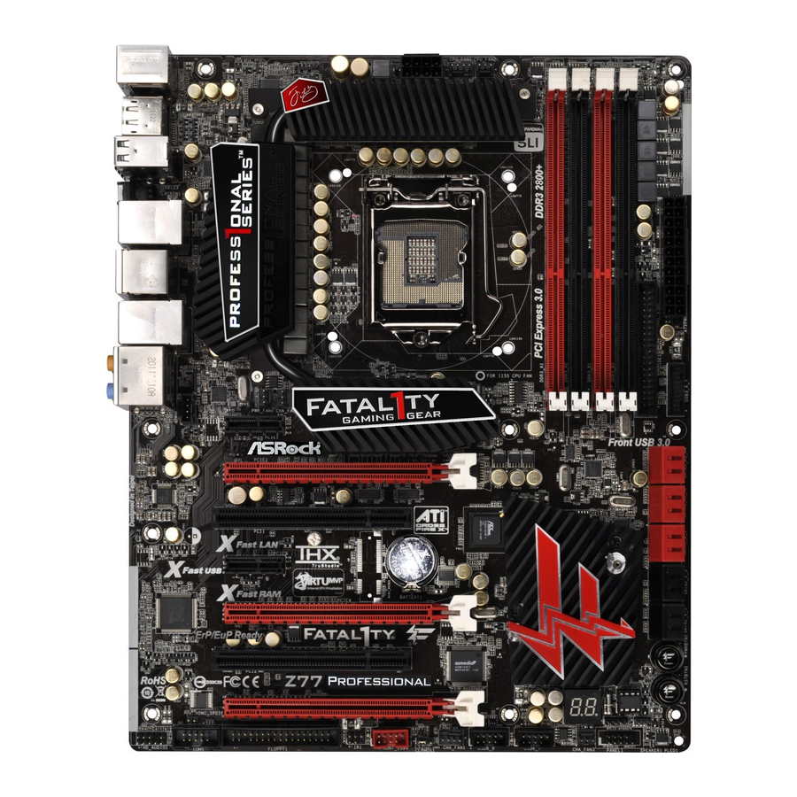
Page 15: Motherboard Layout
1.3 Motherboard Layout 24.4cm (9.6 in) USB 3.0 T: USB0 CPU_FAN1 CPU_FAN2 B: USB1 ATX12V1 USB 3.0 Top: T: USB2 RJ-45 B: USB3 USB 2.0 T: USB4 B: USB5 USB 3.0 Top: T: USB4 RJ-45 B: USB5 PWR_FAN1 CHA_FAN2 USB3_6_7 PCIE1 Front USB 3.0 Z77 PROFESSIONAL... -
Page 16: I/O Panel
1.4 I/O Panel PS/2 Keyboard/Mouse Port (Purple/Green) ** 12 Front Speaker (Lime) DisplayPort (DP1) Microphone (Pink) USB 2.0 Ports (USB01) USB 3.0 Ports (USB3_45) LAN RJ-45 Port IEEE 1394 Port Fatal1ty Mouse Port (USB4) *** 16 eSATA3 Port (ESATA_1) USB 2.0 Port (USB5) USB 3.0 Ports (USB3_23) LAN RJ-45 Port Clear CMOS Switch (CLRCBTN) - Page 17 To enable Multi-Streaming function, you need to connect a front panel audio cable to the front panel audio header. After restarting your computer, you will fi nd “Mixer” tool on your system. Please select “Mixer ToolBox” , click “Enable playback multi-streaming”, and click “ok”.
-
Page 18: Installation
Chapter 2: Installation This is an ATX form factor (12.0" x 9.6", 30.5 x 24.4 cm) motherboard. Before you install the motherboard, study the confi guration of your chassis to ensure that the motherboard fi ts into it. Make sure to unplug the power cord before installing or removing the motherboard. -
Page 19: Cpu Installation
2.3 CPU Installation For the installation of Intel 1155-Pin CPU, please follow the steps below. Load Plate Load Lever Socket Body Contact Array 1155-Pin Socket Overview Before you insert the 1155-Pin CPU into the socket, please check if the CPU surface is unclean or if there are any bent pins in the socket. Do not force to insert the CPU into the socket if above situation is found. - Page 20 Step 3. Insert the 1155-Pin CPU: Step 3-1. Hold the CPU by the edge which is marked with a black line. Step 3-2. Orient the CPU with the IHS (Inte- grated Heat Sink) up. Locate Pin1 and the two orientation key notches. orientation key notch alignment key Pin1...
-
Page 21: Installation Of Cpu Fan And Heatsink
2.4 Installation of CPU Fan and Heatsink This motherboard is equipped with 1155-Pin socket that supports Intel 1155-Pin CPUs. Please adopt the type of heatsink and cooling fan compliant with Intel 1155- Pin CPU to dissipate heat. Before you install the heatsink, you need to spray ther- mal interface material between the CPU and the heatsink to improve heat dissipa- tion. -
Page 22: Installation Of Memory Modules (Dimm)
2.5 Installation of Memory Modules (DIMM) This motherboard provides four 240-pin DDR3 (Double Data Rate 3) DIMM slots, and supports Dual Channel Memory Technology. For dual channel confi g- uration, you always need to install identical (the same brand, speed, size and chip-type) DDR3 DIMM pair in the slots: You have to install identical DDR3 DIMMs in Dual Channel A (DDR3_A1 and DDR3_B1;... -
Page 23: Installing A Dimm
Installing a DIMM Please make sure to disconnect power supply before adding or removing DIMMs or the system components. Step 1. Unlock a DIMM slot by pressing the retaining clips outward. Step 2. Align a DIMM on the slot such that the notch on the DIMM matches the break on the slot. -
Page 24: Expansion Slots (Pci And Pci Express Slots)
PCIE slots: PCIE1 (PCIE 2.0 x1 slot) is used for a PCI Express x1 lane width card, such as a Gigabit LAN card, SATA2 card or ASRock Game Blaster, etc. PCIE3 (PCIE 2.0 x1 slot) is used for a PCI Express x1 lane width card, such as a Gigabit LAN card, SATA2 card, etc. -
Page 25: Installing An Expansion Card
Installing an expansion card Step 1. Before installing an expansion card, please make sure that the power supply is switched off or the power cord is unplugged. Please read the documentation of the expansion card and make necessary hardware settings for the card before you start the installation. Step 2. -
Page 26: Sli Tm And Quad Sli Tm Operation Guide
2.7 SLI and Quad SLI Operation Guide ® This motherboard supports NVIDIA and Quad SLI (Scalable Link Interface) technology that allows you to install up to two identical PCI Express x16 graphics ® ® cards. Currently, NVIDIA technology supports Windows XP / XP 64-bit / ®... - Page 27 Step3. Align and insert SLI_Bridge_2S Card to the goldfi ngers on each graphics card. Make sure SLI_Bridge_2S Card is fi rmly in place. Step4. Connect a VGA cable or a DVI cable to the monitor connector or the DVI connector of the graphics card that is inserted to PCIE2 slot.
- Page 28 2.7.2 Driver Installation and Setup Install the graphics card drivers to your system. After that, you can enable the Multi- ® Graphics Processing Unit (GPU) feature in the NVIDIA nView system tray utility. Please follow the below procedures to enable the multi-GPU feature. ®...
- Page 29 ® For Windows Vista / Vista 64-bit / 7 / 7 64-bit OS: (For SLI and Quad SLI mode) A. Click the Start icon on your Windows taskbar. B. From the pop-up menu, select All Programs, and then click NVIDIA Corporation.
-
Page 30: Crossfirex
CrossFireX , 3-Way CrossFireX and Quad CrossFireX Operation Guide This motherboard supports CrossFireX , 3-way CrossFireX and Quad CrossFireX feature. CrossFireX technology offers the most advantageous means available of combining multiple high performance Graphics Processing Units (GPU) in a single PC. Combining a range of different operating modes with intelligent software design and an innovative interconnect mechanism, CrossFireX enables the highest possible level of performance and image quality in any 3D ®... - Page 31 Step 2. Connect two Radeon graphics cards by installing CrossFire Bridge on CrossFire Bridge Interconnects on the top of Radeon graphics cards. (CrossFire Bridge is provided with the graphics card you purchase, not bundled with this motherboard. Please refer to your graphics card vendor for details.) CrossFire Bridge Step 3.
- Page 32 2.8.1.2 Installing Three CrossFireX -Ready Graphics Cards Step 1. Install one Radeon graphics card to PCIE2 slot. For the proper installation procedures, please refer to section “Expansion Slots”. Step 2. Install one Radeon graphics card to PCIE4 slot. For the proper installation procedures, please refer to section “Expansion Slots”.
- Page 33 CrossFire Bridge Step 5. Connect the DVI monitor cable to the DVI connector on the Radeon graph- ics card on PCIE2 slot. (You may use the DVI to D-Sub adapter to convert the DVI connector to D-Sub interface, and then connect the D-Sub monitor cable to the DVI to D-Sub adapter.)
-
Page 34: Driver Installation And Setup
2.8.2 Driver Installation and Setup Step 1. Power on your computer and boot into OS. Step 2. Remove the ATI driver if you have any VGA driver installed in your system. The Catalyst Uninstaller is an optional download. We recommend using this utility to uninstall any previously installed Catalyst drivers prior to installation. - Page 35 Although you have selected the option “Enable CrossFire ”, the CrossFireX function may not work actually. Your computer will automatically reboot. After restarting your computer, please confi rm whether the option “Enable CrossFire ” in “ATI Catalyst Control Center” is selected or not; if not, please select it again, and then you are able to enjoy the benefi...
-
Page 36: Dual Monitor And Surround Display Features
2.9 Dual Monitor and Surround Display Features Dual Monitor Feature This motherboard supports dual monitor feature. With the internal VGA output sup- port (HDMI and DisplayPort), you can easily enjoy the benefi ts of dual monitor fea- ture without installing any add-on VGA card to this motherboard. This motherboard also provides independent display controllers for HDMI and DisplayPort to support dual VGA output so that HDMI and DisplayPort can drive same or different display contents. - Page 37 Surround Display Feature This motherboard supports surround display upgrade. With the internal VGA output support (HDMI and DisplayPort) and external add-on PCI Express VGA cards, you can easily enjoy the benefi ts of surround display feature. Please refer to the following steps to set up a surround display environment: 1.
- Page 38 ® For Windows 7 / 7 64-bit / Vista / Vista 64-bit OS: Right click the desktop, choose “Personalize”, and select the “Display Settings” tab so that you can adjust the parameters of the multi-monitors according to the steps below. A.
-
Page 39: Jumpers Setup
2.10 Jumpers Setup The illustration shows how jumpers are setup. When the jumper cap is placed on pins, the jumper is “Short”. If no jumper cap is placed on pins, the jumper is “Open”. The illustration shows a 3-pin jumper whose pin1 and pin2 are “Short”... -
Page 40: Onboard Headers And Connectors
2.11 Onboard Headers and Connectors Onboard headers and connectors are NOT jumpers. Do NOT place jumper caps over these headers and connectors. Placing jumper caps over the headers and connectors will cause permanent damage of the motherboard! FDD connector (33-pin FLOPPY1) (see p.15 No. - Page 41 Serial ATA (SATA) Either end of the SATA data Data Cable cable can be connected to the SATA / SATA2 / SATA3 hard (Optional) disk or the SATA2 / SATA3 connector on this motherboard. Serial ATA (SATA) Please connect the black end Power Cable of SATA power cable to the power connector on each drive.
- Page 42 Front Panel Audio Header This is an interface for front PRESENCE# MIC_RET panel audio cable that allows (9-pin HD_AUDIO1) OUT_RET convenient connection and (see p.15, No. 32) control of audio devices. OUT2_L J_SENSE OUT2_R MIC2_R MIC2_L 1. High Defi nition Audio supports Jack Sensing, but the panel wire on the chassis must support HDA to function correctly.
- Page 43 HDLED (Hard Drive Activity LED): Connect to the hard drive activity LED on the chassis front panel. The LED is on when the hard drive is reading or writing data. The front panel design may differ by chassis. A front panel module mainly consists of power switch, reset switch, power LED, hard drive activity LED, speaker and etc.
- Page 44 Though this motherboard provides 4-Pin CPU fan (Quiet Fan) support, the 3-Pin CPU fan still can work successfully even without the fan speed control function. If you plan to connect the 3-Pin CPU fan to the CPU fan connector on this motherboard, please connect it to Pin 1-3.
- Page 45 Serial port Header This COM1 header supports a serial port module. (9-pin COM1) (see p.15, No. 31) HDMI_SPDIF Header HDMI_SPDIF header, providing SPDIF audio output to HDMI (2-pin HDMI_SPDIF1) SPDIFOUT VGA card, allows the system to (see p.15, No. 33) connect HDMI Digital TV/ projector/LCD devices.
- Page 46 The Installation Guide of Front USB 3.0 Panel Step 1 Step 2 Screw the 2.5” HDD/SSD to the Front Prepare the bundled Front USB 3.0 Panel, four USB 3.0 Panel with four HDD screws. HDD screws, and six chassis screws. Step 3 Step 4 Screw the Front USB 3.0 Panel to the...
-
Page 47: Smart Switches
2.12 Smart Switches The motherboard has three smart switches: power switch, reset switch and clear CMOS switch, allowing users to quickly turn on/off or reset the sytem clear the CMOS values. Power Switch Power Switch is a smart switch, allowing users to quickly turn (PWRBTN) Power on/off the system. -
Page 48: Dr. Debug
2.13 Dr. Debug Dr. Debug is used to provide code information, which makes troubleshooting even easier. Please see the diagrams below for reading the Dr. Debug codes. Status Code Description 0x00 Not used 0x01 Power on. Reset type detection (soft/hard) 0x02 AP initialization before microcode loading 0x03... - Page 49 0x37 Post-Memory North Bridge initialization is started 0x38 Post-Memory North Bridge initialization (North Bridge module specifi c) 0x39 Post-Memory North Bridge initialization (North Bridge module specifi c) 0x3A Post-Memory North Bridge initialization (North Bridge module specifi c) 0x3B Post-Memory South Bridge initialization is started 0x3C Post-Memory South Bridge initialization (South Bridge module specifi...
- Page 50 0x62 Installation of the South Bridge Runtime Services 0x63 CPU DXE initialization is started 0x64 CPU DXE initialization (CPU module specifi c) 0x65 CPU DXE initialization (CPU module specifi c) 0x66 CPU DXE initialization (CPU module specifi c) 0x67 CPU DXE initialization (CPU module specifi c) 0x68 PCI host bridge initialization 0x69...
- Page 51 0xA6 SCSI Detect 0xA7 SCSI Enable 0xA8 Setup Verifying Password 0xA9 Start of Setup 0xAA Reserved for ASL (see ASL Status Codes section below) 0xAB Setup Input Wait 0xAC Reserved for ASL (see ASL Status Codes section below) 0xAD Ready To Boot event 0xAE Legacy Boot event 0xAF...
-
Page 52: Serial Ata (Sata) / Serial Ata2 (Sata2) Hard Disks Installation
2.14 Serial ATA (SATA) / Serial ATA2 (SATA2) Hard Disks Installation ® This motherboard adopts Intel Z77 chipset that supports Serial ATA (SATA) / Serial ATA2 (SATA2) hard disks and RAID (RAID 0, RAID 1, RAID 5, RAID 10, Intel Rapid Storage and Intel Smart Response Technology) functions. -
Page 53: Hot Plug And Hot Swap Functions For Sata / Sata2 Hdds
2.16 Hot Plug and Hot Swap Functions for SATA / SATA2 HDDs This motherboard supports Hot Plug and Hot Swap functions for SATA / SATA2 in ® RAID / AHCI mode. Intel Z77 chipset provides hardware support for Advanced Host controller Interface (AHCI), a new programming interface for SATA host controllers developed through a joint industry effort. -
Page 54: Sata / Sata2 / Sata3 Hdd Hot Plug Feature And Operation Guide
SATA / SATA2 / SATA3 Hot Plug support information of our motherboard is indicated in the product spec on our website: www.asrock.com 2. Make sure your SATA / SATA2 / SATA3 HDD can support Hot Plug function from your dealer or HDD user manual. - Page 55 How to Hot Plug a SATA / SATA2 / SATA3 HDD: Points of attention, before you process the Hot Plug: Please do follow below instruction sequence to process the Hot Plug, improper procedure will cause the SATA / SATA2 / SATA3 HDD damage and data loss. Step 1 Step 2 Please connect SATA power cable 1x4-...
-
Page 56: Driver Installation Guide
2.19 Driver Installation Guide To install the drivers to your system, please insert the support CD to your optical drive fi rst. Then, the drivers compatible to your system can be auto-detected and listed on the support CD driver page. Please follow the order from up to bottom side to install those required drivers. - Page 57 STEP 3: Use “RAID Installation Guide” to set RAID confi guration. Before you start to confi gure the RAID function, you need to check the installation guide in the Support CD for proper confi guration. Please refer to the document in the Support CD, “Guide to SATA Hard Disks Installation and RAID Confi...
-
Page 58: Installing Windows
2.20.2 Installing Windows 7 / 7 64-bit / Vista / Vista 64-bit With ® RAID Functions ® If you want to install Windows 7 / 7 64-bit / Vista / Vista 64-bit on your SATA / SATA2 / SATA3 HDDs with RAID functions, please follow below steps. STEP 1: Set up UEFI. -
Page 59: Xp / Xp 64-Bit Without Raid Functions
2.21 Installing Windows 7 / 7 64-bit / Vista / Vista 64-bit / XP / ® XP 64-bit Without RAID Functions ® If you want to install Windows 7 / 7 64-bit / Vista / Vista 64-bit / XP / XP 64- bit OS on your SATA / SATA2 / SATA3 HDDs without RAID functions, please follow below procedures according to the OS you install. -
Page 60: Vista Tm 64-Bit Without Raid Functions
2.21.2 Installing Windows 7 / 7 64-bit / Vista / Vista 64-bit ® Without RAID Functions ® If you want to install Windows 7 / 7 64-bit / Vista / Vista 64-bit OS on your SATA / SATA2 / SATA3 HDDs without RAID functions, please follow below steps. Using SATA / SATA2 / SATA3 HDDs with NCQ function STEP 1: Set Up UEFI. -
Page 61: Teaming Function Operation Guide
2.22 Teaming Function Operation Guide Dual LAN with Teaming function enabled on this motherboard allows two single connections to act as one single connection for twice the transmission bandwidth, making data transmission more effective and improving the quality of transmission of distant images. - Page 62 4. Click the Create Team tab. * The Create Team tab appears only if there are teamable adapters available. 5. Click the Team Name fi eld to enter a team name. 6. Click the Team Type fi eld to select a team type. 7.
- Page 63 9. Type the value for Team MTU. 10. Click Create to save the team information. 11. Repeat steps 5. through 10. to defi ne additional teams. As teams are defi ned, they can be selected from the team list, but they have not yet been created. Click the Preview tab to view the team structure before applying the changes.
- Page 64 14. Confi gure the team IP address. a. From Control Panel, double-click Network Connections. b. Right-click the name of the team to be confi gured, and then click Properties. c. On the General tab, click Internet Protocol (TCP/IP), and then click Properties.
-
Page 65: Uefi Setup Utility
Chapter 3: UEFI SETUP UTILITY 3.1 Introduction This section explains how to use the UEFI SETUP UTILITY to confi gure your system. The UEFI chip on the motherboard stores the UEFI SETUP UTILITY. You may run the UEFI SETUP UTILITY when you start up the computer. Please press <F2>... -
Page 66: Navigation Keys
3.1.2 Navigation Keys Please check the following table for the function description of each navigation key. Navigation Key(s) Function Description Moves cursor left or right to select Screens Moves cursor up or down to select items + / - To change option for the selected items <Tab>... -
Page 67: Oc Tweaker Screen
3.3 OC Tweaker Screen In the OC Tweaker screen, you can set up overclocking features. Load Optimized CPU OC Setting You can use this option to load optimized CPU overclocking setting. Please note that overclocing may cause damage to your CPU and mother- board. - Page 68 Intel Turbo Boost Technology Use this item to enable or disable Intel Turbo Boost Mode Technology. Turbo Boost Mode allows processor cores to run faster than marked fre- quency in specifi c conditions. The default value is [Enabled]. Additional Turbo Voltage Use this item to add voltage when CPU is in Turbo mode.
- Page 69 DRAM Confi guration DRAM tCL Use this item to change CAS# Latency (tCL) Auto/Manual setting. The default is [Auto]. DRAM tRCD Use this item to change RAS# to CAS# Delay (tRCD) Auto/Manual setting. The default is [Auto]. DRAM tRP Use this item to change Row Precharge Time (tRP) Auto/Manual setting. The default is [Auto].
- Page 70 DRAM tRTP Use this item to change Read to Precharge (tRTP) Auto/Manual setting. The default is [Auto]. DRAM tFAW Use this item to change Four Activate Window (tFAW) Auto/Manual set- ting. The default is [Auto]. DRAM tCWL Use this item to change CAS# Write Latency (tCWL) Auto/Manual setting. The default is [Auto].
- Page 71 User Defaults In this option, you are allowed to load and save three user defaults according to your own requirements.
-
Page 72: Advanced Screen
3.4 Advanced Screen In this section, you may set the confi gurations for the following items: CPU Confi gu- ration, North Bridge Confi guration, South Bridge Confi guration, Intel(R) Rapid Start Technology, Intel(R) Smart Connect Technology, Storage Confi guration, Super IO Confi... -
Page 73: Cpu Configuration
3.4.1 CPU Configuration Intel Hyper Threading Technology To enable this feature, a computer system with an Intel processor that sup- ports Hyper-Threading technology and an operating system that includes ® ® optimization for this technology, such as Microsoft Windows XP / Vista ®... - Page 74 to the IA-32 Intel Architecture. An IA-32 processor with “No Execute (NX) Memory Protection” can prevent data pages from being used by malicious software to execute codes. This option will be hidden if the current CPU does not support No-Excute Memory Protection. Intel Virtualization Technology When this option is set to [Enabled], a VMM (Virtual Machine Architecture) can utilize the additional hardware capabilities provided by Vanderpool...
-
Page 75: North Bridge Confi Guration
3.4.2 North Bridge Configuration Primary Graphics Adapter This allows you to select [Onboard], [PCI] or [PCI Express] as the boot graphic adapter priority. The default value is [PCI Express]. Share Memory This allows you to set onboard VGA share memory feature. The default value is [Auto]. -
Page 76: South Bridge Confi Guration
3.4.3 South Bridge Configuration Onboard HD Audio Select [Auto], [Enabled] or [Disabled] for the onboard HD Audio feature. If you select [Auto], the onboard HD Audio will be disabled when PCI Sound Card is plugged. Front Panel Select [Auto] or [Disabled] for the onboard HD Audio Front Panel. Onboard HDMI HD Audio This allows you to enable or disable the Onboard HDMI HD Audio feature. -
Page 77: Intel(R) Rapid Start Technology
3.4.4 Intel(R) Rapid Start Technology Intel(R) Rapid Start Technology Use this item to enable or disable Intel(R) Rapid Start Technology. Intel(R) Rapid Start Technology is a new zero power hibernation mode which al- lows users to resume in just 5-6 seconds. The default is [Disabled]. -
Page 78: Intel(R) Smart Connect Technology
3.4.5 Intel(R) Smart Connect Technology Intel(R) Smart Connect Technology Use this item to enable or disable Intel(R) Smart Connect Technology. Intel(R) Smart Connect Technology keeps your e-mail and social networks, such as Twitter, Facebook, etc. updated automatically while the computer is in sleep mode. -
Page 79: Storage Confi Guration
3.4.6 Storage Configuration SATA Controller(s) Use this item to enable or disable the SATA Controller feature. SATA Mode Selection This item is for SATA3_0, SATA3_1 and SATA2_2 to SATA2_5 ports. Use this to select SATA mode. Confi guration options: [IDE Mode], [AHCI Mode] and [RAID Mode]. -
Page 80: Super Io Confi Guration
® We recommend to use Intel Z77 SATA ports (SATA3_0, SATA3_1, SATA2_2, SATA2_3, SATA2_4 and SATA2_5) for your bootable devices. This will minimum your boot time and get the best performance. But if you still want to boot from ASMedia SATA3 controller, you can still enable this in UEFI. 3.4.7 Super IO Configuration OnBoard Floppy Controller Use this item to enable or disable fl... -
Page 81: Acpi Confi Guration
3.4.8 ACPI Configuration Suspend to RAM Use this item to select whether to auto-detect or disable the Suspend-to- RAM feature. Selecting [Auto] will enable this feature if the OS supports it. Check Ready Bit Use this item to enable or disable the feature Check Ready Bit. ACPI HPET Table Use this item to enable or disable ACPI HPET Table. -
Page 82: Usb Confi Guration
3.4.9 USB Configuration USB 2.0 Controller Use this item to enable or disable the use of USB 2.0 controller. USB 3.0 Controller Use this item to enable or disable the use of USB 3.0 controller. Legacy USB Support Use this option to select legacy support for USB devices. There are four confi... -
Page 83: Hardware Health Event Monitoring Screen
3.5 Hardware Health Event Monitoring Screen In this section, it allows you to monitor the status of the hardware on your system, including the parameters of the CPU temperature, motherboard temperature, CPU fan speed, chassis fan speed, and the critical voltage. CPU Fan 1 &... -
Page 84: Boot Screen
3.6 Boot Screen In this section, it will display the available devices on your system for you to confi g- ure the boot settings and the boot priority. Setup Prompt Timeout This shows the number of seconds to wait for setup activation key. 65535(0XFFFF) means indefi... -
Page 85: Security Screen
3.7 Security Screen In this section, you may set or change the supervisor/user password for the system. For the user password, you may also clear it. -
Page 86: Exit Screen
3.8 Exit Screen Save Changes and Exit When you select this option, the following message “Save confi guration changes and exit setup?” will pop-out. Select [Yes] to save the changes and exit the UEFI SETUP UTILITY. Discard Changes and Exit When you select this option, the following message “Discard changes and exit setup?”... -
Page 87: Software Support
Click on a specifi c item then follow the installation wizard to install it. 4.2.4 Contact Information If you need to contact ASRock or want to know more about ASRock, welcome to visit ASRock’s website at http://www.asrock.com; or you may contact your... - Page 88 Installing OS on a HDD Larger Than 2TB in AHCI Mode ® This motherboard adopts UEFI BIOS that allows Windows OS to be installed on a large size HDD (>2TB). Please follow the procedures below to install the operating system. ®...
-
Page 89: Installing Os On A Hdd Larger Than 2Tb In Raid Mode
RAID drivers into a USB fl ash disk. You can download the driver from ASRock's website and unzip the fi le into a USB fl ash disk OR copy the fi le from ASRock motherboard support CD. (please copy the fi les under following directory: 32 bit: ..\i386\Win7_Vista_Intel_v11.0.0.1032... - Page 90 E. Please keep the USB fl ash disk installed until the system's fi rst reboot. ® F. Continue to install OS by following the Windows instructions. ® 5. Follow Windows Installation Guide to install OS. ® If you install Windows 7 64-bit / Vista 64-bit on a large hard disk (ex.
- Page 91 B. Disable “Volume Shadow Copy” service. a. Type “computer management” in the Start Menu, then press “Enter”. b. Go to “Services and Applications>Services”; Then double click “Volume Shadow Copy”.
- Page 92 c. Set “Startup type” to “Disable” then Click “OK”. C. Reboot your system. D. After reboot, please start to install motherboard drivers and utilities. ® Windows 7 64-bit: A. Please request the hotfi x KB2505454 through this link: http://support.microsoft.com/kb/2505454/ ® B.