Table of Contents
Advertisement
Advertisement
Chapters
Table of Contents

Related Manuals for Asus M4N72-E - Motherboard - ATX


Summary of Contents for Asus M4N72-E - Motherboard - ATX
- Page 1 M4N72-E...
- Page 2 Product warranty or service will not be extended if: (1) the product is repaired, modified or altered, unless such repair, modification of alteration is authorized in writing by ASUS; or (2) the serial number of the product is defaced or missing.
-
Page 3: Table Of Contents
Welcome! ..................1-1 Package contents ................. 1-1 Special features ................1-1 1.3.1 Product highlights ............1-1 1.3.2 Innovative ASUS features ..........1-2 Before you proceed ..............1-4 Motherboard overview ..............1-5 1.5.1 Placement direction ............1-5 1.5.2 Screw holes ..............1-5 1.5.3... -
Page 4: Contents
2.1.1 Creating a bootable floppy disk ........2-1 2.1.2 ASUS Update utility ............2-2 2.1.3 ASUS EZ Flash 2 utility ........... 2-3 2.1.4 AFUDOS utility ..............2-4 2.1.5 ASUS CrashFree BIOS 2 utility ........2-5 BIOS setup program ..............2-6 2.2.1... - Page 5 Boot Device Priority ............2-24 2.7.2 Boot Settings Configuration .......... 2-24 2.7.3 Security ................. 2-25 Tools menu ................. 2-26 2.8.1 ASUS EZ Flash 2 ............2-26 2.8.2 Express Gate [Enabled] ..........2-26 2.8.3 ASUS O.C. Profile ............2-27 2.8.4 AI NET 2................ 2-27...
-
Page 6: Notices
Notices Federal Communications Commission Statement This device complies with Part 15 of the FCC Rules. Operation is subject to the following two conditions: • This device may not cause harmful interference, and • This device must accept any interference received including interference that may cause undesired operation. -
Page 7: Safety Information
Safety information Electrical safety • To prevent electrical shock hazard, disconnect the power cable from the electrical outlet before relocating the system. • When adding or removing devices to or from the system, ensure that the power cables for the devices are unplugged before the signal cables are connected. If possible, disconnect all power cables from the existing system before you add a device. -
Page 8: Conventions Used In This Guide
Refer to the following sources for additional information and for product and software updates. ASUS websites The ASUS website provides updated information on ASUS hardware and software products. Refer to the ASUS contact information. Optional documentation Your product package may include optional documentation, such as warranty flyers, that may have been added by your dealer. -
Page 9: M4N72-E Specifications Summary
CPU limitation, DDR2 1066 is supported by ® AM3/AM2+ CPUs for one DIMM per channel only. Refer to www.asus.com for the memory QVL (Qualified Vendors Lists). ** Due to OS limitation, when installing total memory of 4GB capacity or more, Windows 32-bit operation ®... - Page 10 ASUS Green Design: - EPU - ASUS AI Nap Express Gate ASUS Quiet Thermal Solution: - ASUS Fanless Design: stylish heatsink solution - ASUS Q-Fan 2 ASUS EZ DIY - ASUS Q-Connector - ASUS CrashFree BIOS 2 - ASUS O.C. Profile...
- Page 11 1 x 4-pin ATX 12V Power connector 1 x System Panel (Q-Connector) BIOS features 8 Mb Flash ROM, AMI BIOS, PnP, DMI 2.0, WfM2.0, SM BIOS 2.5, ACPI 2.0, ASUS EZ Flash 2, ASUS CrashFree BIOS 2 Support CD contents Express Gate...
-
Page 13: Chapter 1 Product Introduction
® The motherboard delivers a host of new features and latest technologies, making it another standout in the long line of ASUS quality motherboards! Before you start installing the motherboard, and hardware devices on it, check the items in your package with the list below. -
Page 14: Innovative Asus Features
This enhances system performance in 3D graphics and other memory demanding applications. DDR2 1066 is supported by AM3 / AM2+ CPUs only. Refer to www.asus.com for the supported CPU models. 1.3.2... -
Page 15: Asus Express Gate
O.C. settings in different scenarios. Turbo Key ASUS Turbo Key allows you to turn the PC power button into a physical overclocking button. After the easy setup, Turbo Key boosts performances without interrupting ongoing work or games, simply through pressing the button. -
Page 16: Before You Proceed
ON, in sleep mode, or in soft-off mode. This is a reminder that you should shut down the system and unplug the power cable before removing or plugging in any motherboard component. The illustration below shows the location of the onboard LED. ASUS M4N72-E... -
Page 17: Motherboard Overview
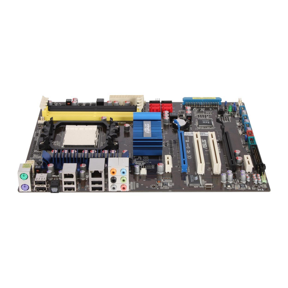
Motherboard overview 1.5.1 Placement direction When installing the motherboard, ensure that you place it into the chassis in the correct orientation. The edge with external ports goes to the rear part of the chassis as indicated in the image below. 1.5.2 Screw holes Place nine (9) screws into the holes indicated by circles to secure the motherboard to the... -
Page 18: Motherboard Layout
Serial port connector (10-1 pin COM1) 1-29 Floppy disk drive connector (34-1 pin FLOPPY) 1-27 Digital audio connector (4-1 pin SPDIF_OUT) 1-28 Optical drive audio in connector (4-pin CD) 1-28 Front panel audio connector (10-1 pin AAFP) 1-29 ASUS M4N72-E... -
Page 19: Central Processing Unit (Cpu)
Central Processing Unit (CPU) The motherboard comes with a CPU socket designed for AMD AM3 Phenom™ II / ® Athlon™ X4 / Athlon™ X3 / Athlon™ X2 processors and AM2+ / AM2 Phenom™ X4 / Phenom™ X3 / Athlon™ X2 / Athlon™ / Sempron™ processors. The CPU socket is not compatible with AMD Opteron™... -
Page 20: Installing The Heatsink And Fan
• If you purchased a separate CPU heatsink and fan assembly, ensure that a Thermal Interface Material is properly applied to the CPU heatsink or CPU before you install the heatsink and fan assembly. CPU Fan CPU Heatsink Retention bracket Retention Module Base Retention bracket lock ASUS M4N72-E... - Page 21 Your boxed CPU heatsink and fan assembly should come with installation instructions for the CPU, heatsink, and the retention mechanism. If the instructions in this section do not match the CPU documentation, follow the latter. Attach one end of the retention bracket to the retention module base. Align the other end of the retention bracket to the retention module base.
-
Page 22: System Memory
• For system stability, use a more efficient memory cooling system to support a full memory load (4 DIMMs) or overclocking condition. 1-10 ASUS M4N72-E... - Page 23 M4N72-E Motherboard Qualified Vendors Lists (QVL) DDR2-1066MHz capability DIMM socket Chip Timing support (Optional) Vendor Part No. Size Chip NO. Voltage Brand Dimm (Bios) Apacer BoxP/N:CH.02GAF.C0KK2 2048MB(Kit of 2) DS N/A Heat-Sink Package 5-5-5-15 • • • (78.0AG9S.9KF) Apacer BoxP/N:CH.04GAF.F0KK2 4096MB(Kit of 2) DS N/A Heat-Sink Package 5-5-5-15...
- Page 24 • KINGSTON KVR800D2N6/4G 4096MB ELPIDA E2108ABSE-8G-E • • NANYA NT 512T64U88B0BY-25C 512MB NT5TU64M8BE-25C • • • NANYA NT1GT64U8HB0BY-25C 1024MB NT5TU64M8BE-25C • • • NANYA NT1GT64U8HCOBY-25D 1024MB NANYA NT5TU64M8CE-25D • NANYA NT2GT64U8HC0BY-AC 2048MB NANYA NT5TU128M8CE-AC • • • 1-12 ASUS M4N72-E...
- Page 25 DDR2-800MHz capability (continued) DIMM socket Chip Timing support (Optional) Vendor Part No. Size Chip NO. Voltage Brand Dimm (Bios) OCZ2FX800C32GK 1024MB Heat-Sink Package • OCZ2G8001G 1024MB Heat-Sink Package • • OCZ2T8002GK(EPP) 1024MB Heat-Sink Package • • OCZ2PX800C32GK 2048MB(Kit of 2) DS Heat-Sink Package 3-4-4 (800-5- 2.35...
- Page 26 • B*: Supports two modules inserted into either the yellow slots or the black slots as one pair of Dual-channel memory configuration. • C*: Supports four modules inserted into both the yellow slots and the black slots as two pairs of Dual-channel memory configuration. Visit the ASUS website for the latest QVL. 1-14 ASUS M4N72-E...
-
Page 27: Installing A Dimm
1.7.3 Installing a DIMM Unplug the power supply before adding or removing DIMMs or other system components. Failure to do so can cause severe damage to both the motherboard and the components. Press the retaining clips outward to DDR2 DIMM notch unlock a DDR2 DIMM socket. -
Page 28: Expansion Slots
This motherboard supports PCI Express x1 network cards, SCSI cards, and other cards that comply with the PCI Express specifications. 1.8.5 PCI Express x16 slot This motherboard supports a PCI Express x16 graphics card that complies with the PCI Express specifications. 1-16 ASUS M4N72-E... -
Page 29: Jumpers
Jumpers Clear RTC RAM (CLRTC) This jumper allows you to clear the Real Time Clock (RTC) RAM in CMOS. You can clear the CMOS memory of date, time, and system setup parameters by erasing the CMOS RTC RAM data. The onboard button cell battery powers the RAM data in CMOS, which include system setup information such as system passwords. - Page 30 OV_CPU jumper, shut down the computer and move the cap back to pins 2-3. • The system may need a better cooling system (for example, a water-cooling system) to work stably under high voltage settings. 1-18 ASUS M4N72-E...
-
Page 31: Keyboard/Mouse Power (3-Pin Ps2_Usbpw56)
Keyboard/mouse power (3-pin PS2_USBPW56) This jumper allows you to enable or disable the keyboard/mouse and USB port 5-6 wake-up feature. When you set this jumper to pins 2-3 (+5VSB), you can wake up the computer by pressing a key on the keyboard (the default is the Space Bar), clicking the mouse or using a USB device. -
Page 32: Connectors
Side Speaker Out port (gray). This port connects the side speakers in an 8-channel audio configuration. Refer to the audio configuration table on next page for the function of the audio ports in 2, 4, 6, or 8-channel configuration. 1-20 ASUS M4N72-E... - Page 33 Audio 2, 4, 6, 8-channel configuration Headset Port 4-channel 6-channel 8-channel 2-channel Light Blue Line In Line In Line In Line In Lime Line Out Front Speaker Out Front Speaker Out Front Speaker Out Pink Mic In Mic In Mic In Mic In Orange –...
-
Page 34: Internal Connectors
These are not jumpers! DO NOT place jumper caps on the fan connectors. Only the CPU_FAN and CHA_FAN1 connectors support the ASUS Q FAN 2 feature. Chassis intrusion connector (4-1 pin CHASSIS) This connector is for a chassis-mounted intrusion detection sensor or switch. Connect one end of the chassis intrusion sensor or switch cable to this connector. - Page 35 • If you are uncertain about the minimum power supply requirement for your system, refer to the Recommended Power Supply Wattage Calculator at http://support.asus. com/PowerSupplyCalculator/PSCalculator.aspx?SLanguage=en-us for details. • The ATX 12 V Specification 2.0-compliant (500W) PSU has been tested to support the...
-
Page 36: Ide Connector (40-1 Pin Pri_Ide)
This prevents incorrect insertion when you connect the IDE cable. • Use the 80-conductor IDE cable for Ultra DMA 133/100/66 IDE devices. If any device jumper is set as “Cable-Select”, ensure that all other device jumpers have the same setting. 1-24 ASUS M4N72-E... - Page 37 NVIDIA nForce 750a SLI Serial ATA connectors (7-pin SATA1-6) ® These connectors are for the Serial ATA signal cables for Serial ATA 3Gb/s hard disk and optical disk drives. The Serial ATA 3Gb/s is backward compatible with Serial ATA 1.5Gb/s specification. The data transfer rate of the Serial ATA 3Gb/s is faster than the standard parallel ATA with 133 MB/s (Ultra DMA133).
-
Page 38: System Panel Connector (20-8 Pin Panel)
Pressing the power switch for more than four seconds while the system is ON turns the system OFF. • Reset button (2-pin RESET) This 2-pin connector is for the chassis-mounted reset button for system reboot without turning off the system power. 1-26 ASUS M4N72-E... -
Page 39: Usb Connectors (10-1 Pin Usb78, Usb910, Usb1112)
USB connectors (10-1 pin USB78, USB910, USB1112) These connectors are for USB 2.0 ports. Connect the USB module cable to any of these connectors, then install the module to a slot opening at the back of the system chassis. These USB connectors comply with USB 2.0 specification that supports up to 480 Mbps connection speed. -
Page 40: Digital Audio Connector (4-1 Pin Spdif_Out)
This connector allows you to receive stereo audio input from sound sources such as a CD-ROM, TV tuner, or MPEG card. Digital audio connector (4-1 pin SPDIF_OUT) This connector is for an additional Sony/Philips Digital Interface (S/PDIF) ports. The S/PDIF module is purchased separately. 1-28 ASUS M4N72-E... -
Page 41: Front Panel Audio Connector (10-1 Pin Aafp)
Front panel audio connector (10-1 pin AAFP) This connector is for a chassis-mounted front panel audio I/O module that supports either High Definition Audio or AC`97 audio standard. Connect one end of the front panel audio I/O module cable to this connector. •... - Page 42 This connector is for an IEEE 1394a port. Connect the IEEE 1394a module cable to this connector, then install the module to a slot opening at the back of the system chassis. Never connect a USB cable to the IEEE 1394a connector. Doing so will damage the motherboard! 1-30 ASUS M4N72-E...
- Page 43 ASUS Q-Connector (system panel) You can use the ASUS Q-Connector to connect/disconnect chassis front panel cables in a few steps. Refer to the instructions below to install the ASUS Q-Connector. Connect the front panel cables to the ASUS Q-Connector. Refer to the labels on the Q-Connector to...
-
Page 44: Software Support
ASUS website at www.asus.com for updates. • For detailed software instructions, see the Manual folder in the Support DVD or download the latest software manual from the ASUS website at www.asus.com. To run the Support DVD Place the Support DVD to the optical drive. The DVD automatically displays the Drivers menu if Autorun is enabled in your computer. -
Page 45: Managing And Updating Your Bios
Save a copy of the original motherboard BIOS file to a bootable floppy disk or a USB flash disk in case you need to restore the BIOS in the future. Copy the original motherboard BIOS using the ASUS Update or AFUDOS utilities. 2.1.1... -
Page 46: Asus Update Utility
2.1.2 ASUS Update utility The ASUS Update is a utility that allows you to manage, save, and update the motherboard BIOS in Windows environment. ® • ASUS Update requires an Internet connection either through a network or an Internet Service Provider (ISP). -
Page 47: Asus Ez Flash 2 Utility
2.1.3 ASUS EZ Flash 2 utility The ASUS EZ Flash 2 feature allows you to update the BIOS without having to use a bootable floppy disk or a DOS-based utility. Download the latest BIOS file from the ASUS website at www.asus.com. -
Page 48: Afudos Utility
• Obtain the AFUDOS utility (afudos.exe) from the bundled support DVD and the latest BIOS file from the ASUS website at www.asus.com. • We recommend that you write the BIOS filename on a piece of paper. You will need to key in the exact BIOS filename at the DOS prompt later. -
Page 49: Asus Crashfree Bios 2 Utility
2.1.5 ASUS CrashFree BIOS 2 utility The ASUS CrashFree BIOS 2 is an auto recovery tool that allows you to restore the BIOS file when it fails or gets corrupted during the updating process. You can update a corrupted BIOS file using the motherboard support DVD or the floppy disk that contains the updated BIOS file. -
Page 50: Bios Setup Program
• The BIOS setup screens shown in this section are for reference purposes only, and may not exactly match what you see on your screen. • Visit the ASUS website at www.asus.com to download the latest BIOS file for this motherboard. -
Page 51: Bios Menu Screen
• The BIOS setup screens shown in this chapter are for reference purposes only, and may not exactly match what you see on your screen. • Visit the ASUS website at www.asus.com to download the latest BIOS information. Chapter 2: BIOS setup... -
Page 52: Navigation Keys
Scroll bar fit on the screen. Press the <Up> / <Down> Pop-up window arrow keys or <Page Up> / <Page Down> keys to display the other items on the screen. ASUS M4N72-E... -
Page 53: Main Menu
Main menu When you enter the BIOS Setup program, the Main menu screen appears, giving you an overview of the basic system information. Refer to section 2.2.1 BIOS menu screen for information on the menu screen items and how to navigate through them. BIOS SETUP UTILITY Main Ai Tweaker Advanced Power Boot Tools Exit System Time... -
Page 54: Sata 1-6
When set to [Disabled], the data transfer from and to the device occurs one sector at a time. Configuration options: [Disabled] [Auto] 2-10 ASUS M4N72-E... -
Page 55: Storage Configuration
PIO Mode [Auto] Selects the PIO mode. Configuration options: [Auto] [0] [1] [2] [3] [4] DMA Mode [Auto] Selects the DMA mode. Configuration options: [Auto] SMART Monitoring [Auto] Sets the Smart Monitoring, Analysis, and Reporting Technology. Configuration options: [Auto] [Disabled] [Enabled] 32Bit Data Transfer [Enabled] Enables or disables 32-bit data transfer. -
Page 56: Ai Tweaker Menu
Use the <+> and <-> keys to adjust the PCIE frequency. You can also type the desired PCIE frequency using the numeric keypad. The values range from 100 to 150. 2.4.2 DRAM Frequency Control [Auto] Allows you to select the DRAM frequency control method. Configuration options: [Auto] [Manual] 2-12 ASUS M4N72-E... -
Page 57: Ht Link Speed [Auto]
DRAM Frequency [667MHz] This item appears only when you set the DRAM Frequency Control item to [Manual] and allows you to manually set the DRAM frequency. Configuration options: [667MHz] [800MHz] [1067MHz] CPU/NB Frequency [Auto] This item appears only when you set the AI Overclocking item to [Manual] and allows selection of the CPU frequency multiplier. - Page 58 DCT0/DCT1 Strength Config [Auto] Allows adjustments of the advanced DRAM strength parameters. Configuration options: [Auto] [DCT 0] [DCT 1] [Both] The following sub-items appear only when you set the DCT0/DCT1 Strength Config item to [DCT 0] or [Both]. 2-14 ASUS M4N72-E...
- Page 59 DCT0:CKE drive strength [Auto] Configuration options: [Auto] [1x] [1.25x] [1.5x] [2x] DCT0:CS/ODT drive strength [Auto] Configuration options: [Auto] [1x] [1.25x] [1.5x] [2x] DCT0:Address/Command drive str [Auto] Configuration options: [Auto] [1x] [1.25x] [1.5x] [2x] DCT0:MEMCLK drive strength [Auto] Configuration options: [Auto] [0.75x] [1x] [1.25x] [1.5x] DCT0:Data drive strength [Auto] Configuration options: [Auto] [0.75x] [1x] [1.25x] [1.5x] DCT0:DQS drive strength [Auto]...
-
Page 60: Cpu Voltage [Auto]
Set to [Disabled] to enhance FSB overclocking ability or [Enabled] for EMI control. Configuration options: [Disabled] [Enabled] 2.4.12 PCIE Spread Spectrum [Disabled] Set to [Disabled] to enhance PCIE overclocking ability or [Linear Down] for EMI control. Configuration options: [Disabled] [Linear Down] 2-16 ASUS M4N72-E... -
Page 61: Sata Spread Spectrum [Disabled]
2.4.13 SATA Spread Spectrum [Disabled] Allows you to adjust the SATA spread spectrum setting. Configuration options: [Disabled] [Linear Down] 2.4.14 PCI Spread Spectrum [Disabled] This item becomes user-configurable only when you set the SATA Spread Spectrum item to [Linear Down]. We recommend that you leave this item to its default setting for system stability. -
Page 62: Chipset
Enables or disables the ECC chip kill feature. Configuration options: [Disabled] [Enabled] DRAM BG SCRUB [Disabled] Disables or sets the DRAM BG Scrub. Configuration options: [Disabled] [40ns] [80ns] [160ns] [320ns] [640ns] [1.28us] [2.56us] [5.12us] [10.2us] [20.5us] [41.0us] [81.9us] [163.8us] [327.7us] [655.4us] [1.31ms] [2.62ms] [5.24ms] [10.49ms] [20.97ms] [42.00ms] [84.00ms] 2-18 ASUS M4N72-E... -
Page 63: Onboard Devices Configuration
Data Cache BG Scrub [Disabled] Disables or sets the Data Cache BG Scrub. This item allows the L1 Data Cache RAM to be corrected when idle. Configuration options: [Disabled] [40ns] [80ns] [160ns] [320ns] [640ns] [1.28us] [2.56us] [5.12us] [10.2us] [20.5us] [41.0us] [81.9us] [163.8us] [327.7us] [655.4us] [1.31ms] [2.62ms] [5.24ms] [10.49ms] [20.97ms] [42.00ms] [84.00ms] L2/L3 Cache BG Scrub [Disabled] Disables or sets the L2/L3 Cache BG Scrub. -
Page 64: Pcipnp
(OS). Setting to Auto allows the system to detect the presence of USB devices at startup. If detected, the USB controller legacy mode is enabled. If no USB device is detected, the legacy USB support is disabled. Configuration options: [Disabled] [Enabled] [Auto] 2-20 ASUS M4N72-E... -
Page 65: Power Menu
Power menu The Power menu items allow you to change the settings for the Advanced Configuration and Power Interface (ACPI) and the Advanced Power Management (APM). Select an item then press <Enter> to display the configuration options. BIOS SETUP UTILITY Main Ai Tweaker Advanced Power Boot Tools Exit Suspend Mode [Auto] Select the ACPI state Repost Video on S3 Resume... -
Page 66: Apm Configuration
N/A. Select [Ignored] if you do not wish to display the detected speed. VCORE / 3.3V / 5V / 12V Voltage The onboard hardware monitor automatically detects the voltage output through the onboard voltage regulators. Select Ignored if you do not wish to display the detected voltage output. 2-22 ASUS M4N72-E... - Page 67 CPU Q-Fan Function [Disabled] Allows you to enable or disable the CPU Q-Fan feature that smartly adjusts the fan speeds for more efficient system operation. Configuration options: [Disabled] [Enabled] Select Fan Type: [PWM Fan] This item appears only when you set the CPU Q-Fan Function item to [Enabled] and allows you to select the CPU fan type you installed on the motherboard.
-
Page 68: Boot Menu
This allows you to enable or disable the full screen logo display feature. Configuration options: [Disabled] [Enabled] Set this item to [Enabled] to use the ASUS MyLogo 2™ feature. AddOn ROM Display Mode [Force BIOS] Sets the display mode for option ROM. Configuration options: [Force BIOS] [Keep Current] Bootup Num-Lock [On] Allows you to select the power-on state for the NumLock. -
Page 69: Security
2.7.3 Security The Security menu items allow you to change the system security settings. Select an item then press <Enter> to display the configuration options. Change Supervisor Password Select this item to set or change the supervisor password. The Supervisor Password item on top of the screen shows the default Not Installed. -
Page 70: Tools Menu
2.8.1 ASUS EZ Flash 2 Allows you to run ASUS EZ Flash 2. When you press <OK>, a confirmation message appears. Use the left/right arrow key to select between [Yes] or [No], then press <OK> to confirm your choice. -
Page 71: Asus O.c. Profile
The first time wizard will run again when you enter the Express Gate environment after clearing its settings. 2.8.3 ASUS O.C. Profile This item allows you to store or load multiple BIOS settings. Add Your CMOS Profile. Allows you to save the current BIOS file to the BIOS Flash. In the Name sub-item, type your profile name and press <Enter>, and then choose a profile number to save your CMOS... -
Page 72: Exit Menu
When you select this option or if you press <F5>, a confirmation window appears. Select OK to load default values. Select Exit & Save Changes or make other changes before saving the values to the non-volatile RAM. 2-28 ASUS M4N72-E...