Table of Contents
Advertisement
Advertisement
Table of Contents

Related Manuals for Asus M4N68T-M


Summary of Contents for Asus M4N68T-M
- Page 1 M4N68T-M...
- Page 2 Product warranty or service will not be extended if: (1) the product is repaired, modified or altered, unless such repair, modification of alteration is authorized in writing by ASUS; or (2) the serial number of the product is defaced or missing.
-
Page 3: Table Of Contents
Contents Notices ... vi Safety information ... vii About this guide ... vii M4N68T-M specifications summary ... ix Chapter: Product introduction Welcome! ... 1-1 Package contents ... 1-1 Special features ... 1-1 1.3.1 Product highlights ... 1-1 1.3.2 Innovative ASUS features ... 1-3 Before you proceed ... - Page 4 Chapter: BIOS information Managing and updating your BIOS ... 2-1 2.1.1 ASUS Update utility ... 2-1 2.1.2 ASUS EZ Flash 2 utility ... 2-2 2.1.3 ASUS CrashFree BIOS utility ... 2-3 BIOS setup program ... 2-4 2.2.1 BIOS menu screen ... 2-5 2.2.2...
- Page 5 Boot Device Priority ... 2-18 2.6.2 Boot Settings Configuration ... 2-18 2.6.3 Security ... 2-19 Tools menu ... 2-21 2.7.1 ASUS EZ Flash 2 ... 2-21 2.7.2 Express Gate ... 2-21 2.7.3 ASUS O.C. Profile ... 2-22 2.7.4 AI NET 2... 2-22...
-
Page 6: Notices
Complying with the REACH (Registration, Evaluation, Authorisation, and Restriction of Chemicals) regulatory framework, we published the chemical substances in our products at ASUS REACH website at http://green.asus.com/english/REACH.htm. DO NOT throw the motherboard in municipal waste. This product has been designed to enable proper reuse of parts and recycling. -
Page 7: Safety Information
Safety information Electrical safety • To prevent electric shock hazard, disconnect the power cable from the electric outlet before relocating the system. • When adding or removing devices to or from the system, ensure that the power cables for the devices are unplugged before the signal cables are connected. If possible, disconnect all power cables from the existing system before you add a device. -
Page 8: Conventions Used In This Guide
Refer to the following sources for additional information and for product and software updates. ASUS websites The ASUS website provides updated information on ASUS hardware and software products. Refer to the ASUS contact information. Optional documentation Your product package may include optional documentation, such as warranty flyers, that may have been added by your dealer. -
Page 9: M4N68T-M Specifications Summary
2 x 240-pin DIMM slots support maximum 8GB unbuffered ECC and non-ECC DDR3 1800(O.C.) / 1600 (O.C.) / 1333 / 1066MHz memory modules * Refer to www.asus.com for the latest Memory QVL (Qualified Vendors List). ** When you install a total memory of 4GB or more,... - Page 10 - HT tuning from 200MHz to 550MHz at 1MHz increment - PCIe frequency tuning from 100MHz up to 150MHz at 1MHz increment ASUS C.P.R. (CPU Parameter Recall) 2 x Serial ATA cables 1 x Ultra DMA 133/100 cable 1 x I/O shield...
-
Page 11: Chapter: Product Introduction
® The motherboard delivers a host of new features and latest technologies, making it another standout in the long line of ASUS quality motherboards! Before you start installing the motherboard, and hardware devices on it, check the items in your package with the list below. - Page 12 Cool ‘n’ Quiet Technology ® This motherboard supports the AMD Cool ‘n’ Quiet technology which ® monitors system operation and automatically adjusts CPU voltage and frequency for a cool and quiet operating environment. Dual-Channel DDR3 1800 (O.C.) support This motherboard supports DDR3 memory that features data transfer rates of 1800 (O.C.)/1600 (O.C.)/1333/1066 MHz to meet the higher bandwidth requirements of the latest operating system, 3D graphics, multimedia, and Internet applications.
-
Page 13: Innovative Asus Features
BIOS file using the bundled support DVD or a USB flash disk that contains the BIOS file. ASUS EZ Flash 2 ASUS EZ Flash 2 allows you to update the BIOS from a USB flash disk before entering the OS. ASUS Q-Fan... - Page 14 (PSU). ASUS EPU ASUS EPU is a unique power saving technology that detects the current system loadings and adjusts the power consumption in real time. ASUS AI NET2 ASUS AI NET2 remotely detects the cable connection immediately after you turn on the system and any faulty cable connections are reported back up to 100 meters at 1 meter accuracy.
-
Page 15: Before You Proceed
ON, in sleep mode, or in soft-off mode. This is a reminder that you should shut down the system and unplug the power cable before removing or plugging in any motherboard component. The illustration below shows the location of the onboard LED. M4N68T-M M4N68T-M Onboard LED ASUS M4N68T-M SB_PWR Standby Power... -
Page 16: Motherboard Overview
Place six screws into the holes indicated by circles to secure the motherboard to the chassis. DO NOT overtighten the screws! Doing so can damage the motherboard. Place this side towards the rear of the chassis. M4N68T-M Chapter 1: Product introduction... -
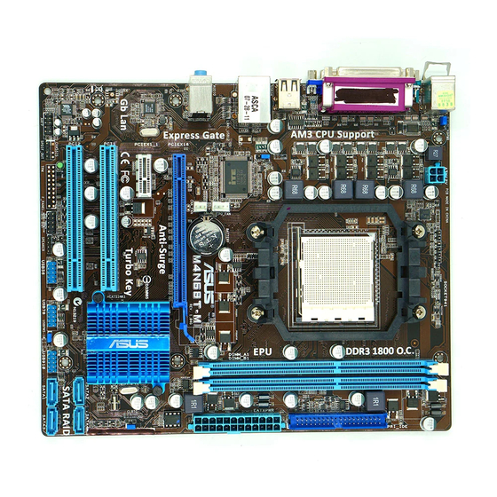
Page 17: Motherboard Layout
ATX power connectors (24-pin EATXPWR, 4-pin ATX12V) CPU and chassis fan connectors (4-pin CPU_FAN and 3-pin CHA_FAN) AMD CPU socket DDR3 DIMM sockets IDE connector (40-1 pin PRI_IDE) Clear RTC RAM (CLRTC) ASUS M4N68T-M 20.8cm(8.2in) CPU_FAN Lithium Cell CMOS Power M4N68T-M PCIEX16 NVIDIA... -
Page 18: Central Processing Unit (Cpu)
To install a CPU: Locate the CPU socket on the motherboard. M4N68T-M M4N68T-M CPU socket AM3 Press the lever sideways to unlock the socket, then lift it up to a 90°-100° angle. Ensure that the socket lever is lifted up to a 90°-100° angle; otherwise, the CPU will not fit in completely. - Page 19 Connect the CPU fan cable to the CPU_FAN connector on the motherboard. M4N68T-M M4N68T-M CPU fan connector DO NOT forget to connect the CPU fan connector! Hardware monitoring errors can occur if you fail to plug this connector.
-
Page 20: Installing The Heatsink And Fan
1.6.2 Installing the heatsink and fan Ensure that you use only AMD-certified heatsink and fan assembly. To install the CPU heatsink and fan: Place the heatsink on top of the installed CPU, ensuring that the heatsink fits properly on the retention module base. •... -
Page 21: System Memory
1.7.1 Overview The motherboard comes with two Double Data Rate 3 (DDR3) Dual Inline Memory Modules (DIMM) sockets. The figure illustrates the location of the DDR3 DIMM sockets: M4N68T-M M4N68T-M 240-pin DDR3 DIMM sockets ASUS M4N68T-M Channel Sockets Channel A... -
Page 22: Memory Configurations
Install a maximum of 3GB system memory if you are using a 32-bit Windows Use a 64-bit Windows motherboard. • This motherboard does not support DIMMs made up of 256 megabits (Mb) chips or less. M4N68T-M Motherboard Qualified Vendors Lists (QVL) DDR3-1800(O.C.)MHz capability Vendor Part No. -
Page 23: Ddr3-1333 Mhz Capability
4096MB(Kit of 2) Crucial BL25664BN1337.16FF 6144MB(Kit of 3 ) DS (XMP) Crucial CT25664BA1339.16SFD 6144MB(Kit of 3 ) DS ASUS M4N68T-M Size Brand Chip NO. 2048MB(Kit of 2) Heat-Sink Package 9-9-9-24 2048MB Heat-Sink Package 8-8-8-21 6144MB(Kit of 3) Heat-Sink Package 9-9-9-24... - Page 24 DDR3-1333MHz capability Vendor Part No. G.SKILL F3-10600CL8D-2GBHK G.SKILL F3-10600CL9D-2GBPK G.SKILL F3-10666CL7T-3GBPK G.SKILL F3-10666CL9T-3GBNQ G.SKILL F3-10600CL7D-2GBPI G.SKILL F3-10600CL9D-2GBNQ G.SkiLL F3-10666CL8D-4GBHK G.SKILL F3-10666CL7T-6GBPK G.SKILL F3-10666CL9T-6GBNQ GEIL DDR3-1333 CL9-9-9-24 GEIL GV34GB1333C7DC GEIL GG34GB1333C9DC GEIL DDR3-1333 CL9-9-9-24 Kingmax FLFD45F-B8MH9 MAES Kingmax FLFE85F-B8MF9 Kingmax FLFE85F-B8MH9 MEES Kingston KVR1333D3N9/1G Kingston...
- Page 25 • A*: Supports one module inserted into either slot as single-channel memory configuration. • B*: Supports one pair of modules inserted into both the blue slots as one pair of dual-channel memory configuration. Visit the ASUS website at www.asus.com for the latest QVL. ASUS M4N68T-M Brand Chip NO.
-
Page 26: Installing A Dimm
1.7.3 Installing a DIMM Unplug the power supply before adding or removing DIMMs or other system components. Failure to do so can cause severe damage to both the motherboard and the components. Press the retaining clips outward to unlock a DIMM socket. Align a DIMM on the socket such that the notch on the DIMM matches the break on the socket. -
Page 27: Expansion Slots
This motherboard supports PCI Express x1 network cards, SCSI cards, and other cards that comply with the PCI Express specifications. 1.8.5 PCI Express x16 slot This motherboard supports a PCI Express x16 graphics card that comply with the PCI Express specifications. ASUS M4N68T-M 1-17... -
Page 28: Jumpers
CMOS RTC RAM data. The onboard button cell battery powers the RAM data in CMOS, which include system setup information such as system passwords. M4N68T-M M4N68T-M Clear RTC RAM To erase the RTC RAM: 1. Turn OFF the computer and unplug the power cord. -
Page 29: Usb Device Wake-Up
(no power to CPU, DRAM in slow refresh, power supply in reduced power mode). M4N68T-M M4N68T-M USB Device Wake Up Keyboard power (3-pin KBPWR) This jumper allows you to enable or disable the keyboard wake-up feature. When you set this jumper to pins 2-3 (+5VSB), you can wake up the computer by pressing a key on the keyboard (the default is the Space Bar). -
Page 30: Connectors
1.10 Connectors 1.10.1 Rear panel ports PS/2 Mouse port (green). This port is for a PS/2 mouse. Parallel port. This 25-pin port connects a parallel printer, a scanner, or other devices. LAN (RJ-45) port. This port allows Gigabit connection to a Local Area Network (LAN) through a network hub. -
Page 31: Internal Connectors
High Definition Audio or AC`97 audio standard. Connect one end of the front panel audio I/O module cable to this connector. M4N68T-M M4N68T-M Analog front panel connector • We recommend that you connect a high-definition front panel audio module to this connector to avail of the motherboard high-definition audio capability. -
Page 32: Atx Power Connectors
The system may become unstable or may not boot up if the power is inadequate. • If you are uncertain about the minimum power supply requirement for your system, refer to the Recommended Power Supply Wattage Calculator at http://support.asus. com/PowerSupplyCalculator/PSCalculator.aspx?SLanguage=en-us for details. 1-22... - Page 33 • Use the 80-conductor IDE cable for Ultra DMA 133/100 IDE devices. If any device jumper is set as “Cable-Select”, ensure that all other device jumpers have the same setting. M4N68T-M M4N68T-M IDE connector ASUS M4N68T-M Drive jumper setting Mode of device(s)
-
Page 34: Serial Ata Connectors
Manual in the support DVD. Internal speaker connector (4-pin SPEAKER) The 4-pin connector is for the chassis-mounted system warning speaker. The speaker allows you to hear system beeps and warnings. M4N68T-M M4N68T-M Speaker Out Connector 1-24 SATA2 SATA4 SATA1 SATA3 XP Service Pack 2 or later versions before using Serial ATA. -
Page 35: System Panel Connector
System panel connector (10-1 pin F_PANEL) This connector supports several chassis-mounted functions. M4N68T-M M4N68T-M System panel connector • System power LED (2-pin PWRLED) This 2-pin connector is for the system power LED. Connect the chassis power LED cable to this connector. The system power LED lights up when you turn on the system power, and blinks when the system is in sleep mode. -
Page 36: Usb Connectors
These USB connectors comply with USB 2.0 specification that supports up to 480Mbps connection speed. M4N68T-M M4N68T-M USB2.0 connectors Never connect a 1394 cable to the USB connectors. Doing so will damage the motherboard! The USB 2.0 module is purchased separately. - Page 37 DO NOT forget to connect the fan cables to the fan connectors. Insufficient air flow inside the system may damage the motherboard components. These are not jumpers! DO NOT place jumper caps on the fan connectors. Only the 4-pin CPU fan connector supports the ASUS Q-Fan feature. ASUS M4N68T-M SPDIF_OUT...
-
Page 38: Software Support
The contents of the Support DVD are subject to change at any time without notice. Visit the ASUS website at www.asus.com for updates. To run the Support DVD Place the Support DVD into the optical drive. -
Page 39: Managing And Updating Your Bios
BIOS in the future. Copy the original motherboard BIOS using the ASUS Update utility. 2.1.1 ASUS Update utility The ASUS Update is a utility that allows you to manage, save, and update the motherboard BIOS in Windows environment. ®... -
Page 40: Asus Ez Flash 2 Utility
Follow the onscreen instructions to complete the updating process. 2.1.2 ASUS EZ Flash 2 utility The ASUS EZ Flash 2 feature allows you to update the BIOS without using an OS-based utility. Before you start using this utility, download the latest BIOS file from the ASUS website at www.asus.com. -
Page 41: Asus Crashfree Bios Utility
2.1.3 ASUS CrashFree BIOS utility The ASUS CrashFree BIOS is an auto recovery tool that allows you to restore the BIOS file when it fails or gets corrupted during the updating process. You can restore a corrupted BIOS file using the motherboard support DVD or a removable device that contains the updated BIOS file. -
Page 42: Bios Setup Program
• The BIOS setup screens in this chapter are for reference only. They may not exactly match what you see on your screen. • Visit the ASUS website at www.asus.com to download the latest BIOS file for this motherboard. Chapter 2: BIOS information... -
Page 43: Bios Menu Screen
At the bottom right corner of a menu screen are the navigation keys for that particular menu. Use the navigation keys to select items in the menu and change the settings. Some of the navigation keys differ from one screen to another. ASUS M4N68T-M Configuration fields BIOS SETUP UTILITY... -
Page 44: Menu Items
2.2.4 Menu items The highlighted item on the menu bar displays the specific items for that menu. For example, selecting Main shows the Main menu items. The other items (Advanced, Power, Boot, Tools, and Exit) on the menu bar have their respective menu items. -
Page 45: Main Menu
Enables or disables the onboard IDE port. Configuration options: [Disabled] [Enabled] Serial-ATA Devices [SATA1,2,3,4] Configuration options: [Disabled] [SATA 1,2] [SATA1,2,3,4] nVidia RAID Function [Disabled] Enables or disables the nVidia RAID function. Configuration options: [Disabled] [Enabled] ASUS M4N68T-M BIOS SETUP UTILITY Boot Tools Exit... - Page 46 2.3.4 Primary IDE Master/Slave, SATA 1/2/3/4 While entering Setup, the BIOS automatically detects the presence of IDE/SATA devices. There is a separate submenu for each IDE/SATA device. Select a device item then press <Enter> to display the IDE/SATA device information. The BIOS automatically detects the values opposite the dimmed items (Device, Vendor, Size, LBA Mode, Block Mode, PIO Mode, Async DMA, Ultra DMA, and SMART monitoring).
-
Page 47: System Information
The items and configuration options in this menu may vary depending on the AMD CPU type. CPU OverClocking [Auto] Selects the CPU overclocking options to achieve desired CPU internal frequency. Configuration options: [Manual] [Auto] [Standard] [Overclock Profile] ASUS M4N68T-M BIOS SETUP UTILITY Boot Tools Exit Adjust System Frequency/Voltage etc. - Page 48 The following item only appears when you set CPU Overclocking to [Manual]. CPU/HT Reference Clock (MHz) [200] Sets the CPU/HT Reference Clock. Configuration options: [Min.��200] [Max.��300] The following item only appears when you set CPU Overclocking to [Overclock Profile]. Overclock Options [Auto] Selects the overclocking profile.
- Page 49 Chipset Over Voltage [Auto] Sets the chipset over voltage. The values range from 1.20000V to 1.60000V with a 0.01000V increment. Use the <+> / <-> keys to adjust the value. Configuration options: [Auto] [Max. �� 1.60000V] [Min. �� 1.20000V] ASUS M4N68T-M 2-11...
-
Page 50: Cpu Configuration
2.4.2 CPU Configuration The items in this menu show the CPU-related information that the BIOS automatically detects. GART Error Reporting [Disabled] This option should remain disabled for the normal operation. The driver developer may enable it for testing purpose. Configuration options: [Disabled] [Enabled] Microcode Updation [Enabled] Enables or disables Microcode Updation. -
Page 51: Southbridge Configuration
Configuration options: [HD Audio] [AC97] MAC LAN [Disabled] Enables or disables the onboard LAN controller. Configuration options: [Enabled] [Disabled] OnBoard LAN Boot ROM [Disabled] This item appears only when the MAC LAN item is set to [Auto]. Configuration options: [Disabled] [Enabled] ASUS M4N68T-M 2-13... -
Page 52: Onboard Device Configuration
2.4.4 Onboard Device Configuration Serial Port1 Address [3F8/IRQ4] Allows you to select the Serial Port1 base address. Configuration options: [Disabled] [3F8/IRQ4][2F8/IRQ3] [3E8/IRQ4] [2E8/IRQ3] Serial Port1 Mode [Normal] Allows you to select the Serial Port1 mode. Configuration options: [Normal] [IrDA] [ASK IR] Parallel Port Address [378] Allows you to select the Parallel Port base addresses. -
Page 53: Usb Configuration
Sets the maximum time that the BIOS waits for the USB storage device to initialize. Configuration options: [10 Sec] [20 Sec] [30 Sec] [40 Sec] Emulation Type [Auto] Allows you to set the emulation type. Configuration options: [Auto] [Floppy] [Forced FDD] [Hard Disk] [CDROM] ASUS M4N68T-M 2-15... -
Page 54: Power Menu
Power menu The Power menu items allow you to change the settings for the Advanced Configuration and Power Interface (ACPI) and the Advanced Power Management (APM). Select an item then press <Enter> to display the configuration options. Main Advanced Power Settings Suspend Mode ACPI 2.0 Support ACPI APIC Support... -
Page 55: Hw Monitor Configuration
The onboard hardware monitor automatically detects the voltage output through the onboard voltage regulators. Smart Q-Fan Function [Disabled] Enables or disables the ASUS Q-Fan feature that smartly adjusts the CPU fan speeds for more efficient system operation. Configuration options: [Disabled] [Enabled] 2.5.6 Anti Surge Support [Enabled] Enables or disables the Anti-Surge function. -
Page 56: Boot Menu
Configuration options: [Removable Dev.] [Hard Drive] [ATAPI CD-ROM] [Disabled] • To select the boot device during system startup, press <F8> when ASUS logo appears. • To access Windows OS in Safe Mode, do any of the following: •... -
Page 57: Security
<Enter> twice. The message Password uninstalled appears. If you forget your BIOS password, you can clear it by erasing the CMOS Real Time Clock (RTC) RAM. See section 1.9 Jumpers for information on how to erase the RTC RAM. ASUS M4N68T-M 2-19... -
Page 58: Change User Password
After you have set a supervisor password, the other items appear to allow you to change other security settings. User Access Level [Full Access] This item allows you to select the access restriction to the Setup items. Configuration options: [No Access] [View Only] [Limited] [Full Access] No Access prevents user access to the Setup utility. -
Page 59: Tools Menu
2.7.1 ASUS EZ Flash 2 Allows you to run ASUS EZ Flash 2. When you press <Enter>, a confirmation message appears. Use the left/right arrow key to select between [Yes] or [No], then press <Enter> to confirm your choice. Please see section 2.1.2 for details. -
Page 60: Asus O.c. Profile
2.7.3 ASUS O.C. Profile This item allows you to store or load multiple BIOS settings. Add Your CMOS Profile Allows you to save the current BIOS file to the BIOS Flash. In the Name sub-item, type your profile name and press <Enter>, and then choose a profile number to save your CMOS settings in the Save to sub-item. -
Page 61: Exit Menu
When you select this option or if you press <F5>, a confirmation window appears. Select OK to load default values. Select Exit & Save Changes or make other changes before saving the values to the non-volatile RAM. ASUS M4N68T-M BIOS SETUP UTILITY Boot... - Page 62 2-24 Chapter 2: BIOS information...