Table of Contents
Advertisement
Advertisement
Table of Contents

Related Manuals for Asus M4A88T-M


Summary of Contents for Asus M4A88T-M
- Page 1 M4A88T-M...
- Page 2 Product warranty or service will not be extended if: (1) the product is repaired, modified or altered, unless such repair, modification of alteration is authorized in writing by ASUS; or (2) the serial number of the product is defaced or missing.
-
Page 3: Table Of Contents
Contents Notices ......................vi Safety information ..................vii About this guide ..................vii M4A88T-M specifications summary ............ix Chapter 1: Product introduction Welcome! ..................1-1 Package contents ................. 1-1 Special features ................1-1 1.3.1 Product highlights ............1-1 1.3.2 Innovative ASUS features ..........1-3 Before you proceed .............. - Page 4 Chapter 2: BIOS information Managing and updating your BIOS ..........2-1 2.1.1 ASUS Update ..............2-1 2.1.2 ASUS EZ Flash 2 ............2-2 2.1.3 ASUS CrashFree BIOS 3 ..........2-3 BIOS setup program ..............2-4 2.2.1 BIOS menu screen ............2-5 2.2.2...
- Page 5 Boot Device Priority ............2-19 2.6.2 Boot Settings Configuration .......... 2-19 2.6.3 Security ................. 2-20 Tools menu ................. 2-21 2.7.1 ASUS EZ Flash 2 ............2-21 2.7.2 Express Gate ..............2-22 2.7.3 ASUS O.C. Profile ............2-22 2.7.4 AI NET 2................ 2-23...
-
Page 6: Notices
Complying with the REACH (Registration, Evaluation, Authorisation, and Restriction of Chemicals) regulatory framework, we published the chemical substances in our products at ASUS REACH website at http://green.asus.com/english/REACH.htm. DO NOT throw the motherboard in municipal waste. This product has been designed to enable proper reuse of parts and recycling. -
Page 7: Safety Information
Safety information Electrical safety • To prevent electric shock hazard, disconnect the power cable from the electric outlet before relocating the system. • When adding or removing devices to or from the system, ensure that the power cables for the devices are unplugged before the signal cables are connected. If possible, disconnect all power cables from the existing system before you add a device. -
Page 8: Conventions Used In This Guide
Refer to the following sources for additional information and for product and software updates. ASUS websites The ASUS website provides updated information on ASUS hardware and software products. Refer to the ASUS contact information. Optional documentation Your product package may include optional documentation, such as warranty flyers, that may have been added by your dealer. -
Page 9: M4A88T-M Specifications Summary
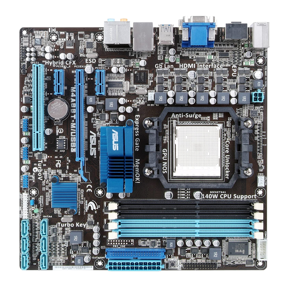
* Due to the CPU limitation, AMD 100 and 200 series CPUs support up to DDR3 1066Mhz. ** Refer to www.asus.com for the latest Memory QVL (Qualified Vendors List). *** Install a 64-bit Windows OS when you want to install 4GB or ®... - Page 10 Express Gate ASUS Exclusive Features MemOK! Core Unlocker Anti-Surge Protection ASUS EPU-4 Engine ASUS Quiet Thermal Solution ASUS Fanless Design: Heatsink Solution ASUS Q-Fan ASUS EZ DIY ASUS O.C. Profile ASUS CrashFree BIOS 3 ASUS EZ Flash 2 ASUS MyLogo 2...
- Page 11 1 x 4-pin ATX 12V power connector 1 x MemOK! button BIOS 16Mb Flash ROM, AMI BIOS, PnP, DMI 2.0, WfM 2.0, SM BIOS 2.5,ACPI 2.0a, ASUS EZ Flash 2, CrashFree BIOS 3 Accessories 1 x Ultra DMA 133/100/66 cable...
-
Page 13: Chapter 1: Product Introduction
® The motherboard delivers a host of new features and latest technologies, making it another standout in the long line of ASUS quality motherboards! Before you start installing the motherboard, and hardware devices on it, check the items in your package with the list below. - Page 14 880G Chipset ® The AMD 880G Chipset is designed to support up to 5200MT/s ® HyperTransport™ 3.0 (HT 3.0) interface speed and PCI Express 2.0 x16 graphics. It is optimized with AMD’s latest AM3 multi-core CPUs to provide excellent system performance and overclocking capabilities. HyperTransport™...
-
Page 15: Innovative Asus Features
Internet without entering the Windows ® • ASUS Express Gate supports installation on SATA HDDs, USB HDDs and flash drives with at least 1.2GB free disk space. When installing it on USB HDDs or flash drives, connect the drives to the motherboard USB port before turning on the computer. -
Page 16: Asus Turbov
BIOS file using the bundled support DVD or a USB flash disk that contains the BIOS file. ASUS EZ Flash 2 ASUS EZ Flash 2 allows you to update the BIOS from a USB flash disk before entering the OS. ASUS EPU ASUS EPU is a unique power saving technology that detects the current system loadings and adjusts the power consumption in real time. -
Page 17: Asus Mylogo 2
ASUS AI NET 2 ASUS AI NET 2 remotely detects the cable connection immediately after you turn on the system and any faulty cable connections are reported back up to 100 meters at 1 meter accuracy. -
Page 18: Before You Proceed
Before you proceed Take note of the following precautions before you install motherboard components or change any motherboard settings. • Unplug the power cord from the wall socket before touching any component. • Before handling components, use a grounded wrist strap or touch a safely grounded object or a metal object, such as the power supply case, to avoid damaging them due to static electricity. -
Page 19: Motherboard Overview
Screw holes Place eight screws into the holes indicated by circles to secure the motherboard to the chassis. DO NOT overtighten the screws! Doing so can damage the motherboard. Place this side towards the rear of the chassis. M4A88T-M ASUS M4A88T-M... -
Page 20: Motherboard Layout
24.4cm(9.6in) KB_USB56 ATX12V COM1 CPU_FAN Super SPDIFO_ HDMI MemOK! DRAM_LED USB34 CHA_FAN LAN1_USB12 ® AUDIO 880G PCIEX1_1 8111E PCIEX16 M4A88T-M ® 16Mb SB710 Lithium Cell PCIEX1_2 BIOS CMOS Power SATA4 SATA5 SATA6 PCI1 SB_PWR VT1708S CLRTC USB78 USB910 USB1112 PANEL... -
Page 21: Central Processing Unit (Cpu)
Installing the CPU To install a CPU: Locate the CPU socket on the motherboard. M4A88T-M M4A88T-M CPU Socket AM3 Press the lever sideways to unlock the Socket lever socket, then lift it up to a 90°-100° angle. Ensure that the socket lever is lifted up to a 90°-100° angle; otherwise, the CPU will not fit in completely. - Page 22 Connect the CPU fan cable to the CPU_FAN connector on the motherboard. CPU_FAN M4A88T-M M4A88T-M CPU fan connector DO NOT forget to connect the CPU fan connector! Hardware monitoring errors can occur if you fail to plug this connector. 1-10...
-
Page 23: Installing The Heatsink And Fan
Your boxed CPU heatsink and fan assembly should come with installation instructions for the CPU, heatsink, and the retention mechanism. If the instructions in this section do not match the CPU documentation, follow the latter. Attach one end of the retention bracket to the retention module base. ASUS M4A88T-M 1-11... -
Page 24: System Memory
The figure illustrates the location of the DDR3 DIMM sockets: Channel Sockets Channel A DIMM_A1 and DIMM_A2 Channel B DIMM_B1 and DIMM_B2 M4A88T-M M4A88T-M 240-pin DDR3 DIMM sockets 1-12 Chapter 1: Product introduction... -
Page 25: Memory Configurations
The motherboard supports up to 16GB memory modules on Windows XP Professional x64 ® and Vista x64 editions. You may install a maximum of 4GB DIMMs on each slot. M4A88T-M Motherboard Qualified Vendors Lists (QVL) DDR3 1866 (O.C.) MHz capability DIMM support Chip Vendor Part No. - Page 26 DDR3 1600 (O.C.) MHz capability DIMM support Chip Vendor Part No. Size Chip NO. Brand A-Data AD31600X002GMU 4096MB(Kit of 2) Heat-Sink Package 7-7-7-20 • Corsair CM3X1G1600C9DHX 2048MB(Kit of 2) Heat-Sink Package 9-9-9-24 • • • CRUCIAL BL12864BA1608.8SFB(XMP) 3072MB(Kit of 3) Heat-Sink Package 8-8-8-24 •...
- Page 27 2048MB Heat-Sink Package • PATRIOT PSD31G13332H 1024MB Heat-Sink Package • • • Patriot PSD31G13332 1024MB Patriot PM64M8D38U-15 • • Takems TMS1GB364D081-107EY 1024MB Heat-Sink Package 7-7-7-20 • • • Takems TMS1GB364D081-138EY 1024MB Heat-Sink Package 8-8-8-24 • • • ASUS M4A88T-M 1-15...
- Page 28 Dual-channel memory configuration. • C*: Supports two pairs of modules inserted into both the blue and the black slots as two pairs of Dual-channel memory configuration. Visit the ASUS website at www.asus.com for the latest QVL. 1-16 Chapter 1: Product introduction...
-
Page 29: Installing A Dimm
DIMM. Support the DIMM lightly with your fingers when pressing the retaining clips. The DIMM might get damaged when it flips out with extra force. DIMM notch Remove the DIMM from the socket. ASUS M4A88T-M 1-17... -
Page 30: Expansion Slots
Expansion slots In the future, you may need to install expansion cards. The following sub-sections describe the slots and the expansion cards that they support. Unplug the power cord before adding or removing expansion cards. Failure to do so may cause you physical injury and damage motherboard components. -
Page 31: Jumpers
Normal Clear RTC (Default) M4A88T-M Clear RTC RAM To erase the RTC RAM: 1. Turn OFF the computer and unplug the power cord. 2. Move the jumper cap from pins 1-2 (default) to pins 2-3. Keep the cap on pins 2-3 for about 5~10 seconds, then move the cap back to pins 1-2. -
Page 32: Connectors
1.10 Connectors 1.10.1 Rear panel ports 5 6 7 8 PS/2 keyboard / mouse combo port. This port is for a PS/2 keyboard or mouse. Optical S/PDIF_OUT port. This port connects to an external audio output device via an optical S/PDIF cable. VGA port. - Page 33 Dual display outputs Supported Not supported DVI + D-Sub • DVI + HDMI • HDMI + D-Sub • • During POST, only the monitor connected to the D-Sub port has display. The dual display function works only under Windows. ASUS M4A88T-M 1-21...
- Page 34 Playback of Blu-ray discs • For better playback quality, we recommend that you follow the system requirements listed below. Suggested list Phenom™ II x4 955 ® DIMM DDR3 1333 BIOS setup Frame Buffer Size – 256MB or higher Playback software CyberLink PowerDVD 9 ®...
-
Page 35: Internal Connectors
The system may become unstable or may not boot up if the power is inadequate. • If you are uncertain about the minimum power supply requirement for your system, refer to the Recommended Power Supply Wattage Calculator at http://support.asus. com/PowerSupplyCalculator/PSCalculator.aspx?SLanguage=en-us for details. ASUS M4A88T-M... -
Page 36: Ide Connectors
If any device jumper is set as “Cable-Select”, ensure that all other device jumpers have the same setting. PRI_IDE M4A88T-M NOTE:Orient the red markings on the IDE ribbon cable to PIN 1. M4A88T-M IDE connector 1-24 Chapter 1: Product introduction... - Page 37 SATA1 SATA2 SATA3 M4A88T-M M4A88T-M SATA connectors • Install the Windows XP Service Pack 1 or later versions before using Serial ATA. ® • If you intend to create a Serial ATA RAID set using these connectors, set the SATA Port1-Port4 and SATA Port5-Port6 items in the BIOS to [RAID].
-
Page 38: System Panel Connector (20-8 Pin Panel)
IDE_LED PWRSW RESET * Requires an ATX power supply M4A88T-M System panel connector • System power LED (2-pin PLED) This 2-pin connector is for the system power LED. Connect the chassis power LED cable to this connector. The system power LED lights up when you turn on the system power, and blinks when the system is in sleep mode. - Page 39 The connector is for a serial (COM) port. Connect the serial port module cable to the connector, then install the module to a slot opening at the back of the system chassis. The serial port module is purchased separately. COM1 PIN 1 M4A88T-M M4A88T-M Serial port (COM1) connector ASUS M4A88T-M 1-27...
-
Page 40: Digital Audio Connector
Legacy AC’97 pin definition compliant definition M4A88T-M Front panel audio connector • We recommend that you connect a high-definition front panel audio module to this connector to avail of the motherboard high-definition audio capability. • If you want to connect a high definition front panel audio module to this connector, set the Front Panel Select item in the BIOS to [HD Audio]. - Page 41 These are not jumpers! DO NOT place jumper caps on the fan connectors. Only the 4-pin CPU fan supports the ASUS Q-Fan feature. LPT connector (26-1 pin LPT) The LPT (Line Printing Terminal) connector supports devices such as a printer. LPT is standardized as IEEE 1284, which is the parallel port interface on IBM PC-compatible computers.
-
Page 42: Onboard Switch
If the installed DIMMs still fail to boot after the whole tuning process, the DRAM_LED lights continuously. Replace the DIMMs with ones recommended in the Memory QVL (Qualified Vendors Lists) in this user manual or on the ASUS website at www.asus.com. -
Page 43: Onboard Leds
SB_PWR M4A88T-M Standby Power Powered Off M4A88T-M Onboard Power LED DRAM LED DRAM LED checks the DRAM in sequence during motherboard booting process. If an error is found , the LED next to the error device will continue lighting until the problem is solved. -
Page 44: Software Support
The contents of the Support DVD are subject to change at any time without notice. Visit the ASUS website at www.asus.com for updates. To run the Support DVD Place the Support DVD into the optical drive. -
Page 45: Chapter 2: Bios Information
BIOS in the future. Copy the original motherboard BIOS using the ASUS Update utility. 2.1.1 ASUS Update The ASUS Update is a utility that allows you to manage, save, and update the motherboard BIOS in Windows environment. ®... -
Page 46: Asus Ez Flash 2
Follow the onscreen instructions to complete the updating process. 2.1.2 ASUS EZ Flash 2 The ASUS EZ Flash 2 feature allows you to update the BIOS without using an OS-based utility. Before you start using this utility, download the latest BIOS file from the ASUS website at www.asus.com. -
Page 47: Asus Crashfree Bios 3
2.1.3 ASUS CrashFree BIOS 3 ASUS CrashFree BIOS 3 is an auto recovery tool that allows you to restore the BIOS file when it fails or gets corrupted during the updating process. You can restore a corrupted BIOS file using the motherboard support DVD or a USB flash drive that contains the BIOS file. -
Page 48: Bios Setup Program
• The BIOS setup screens in this chapter are for reference only. They may not exactly match what you see on your screen. • Visit the ASUS website at www.asus.com to download the latest BIOS file for this motherboard. Chapter 2: BIOS information... -
Page 49: Bios Menu Screen
2.2.1 BIOS menu screen Menu items Menu bar Configuration fields General help M4A88T-M BIOS Setup Version 2106 Main Advanced Power Boot Tools Exit Main Settings Use [ENTER], [TAB] System Time [19:34:30] or [SHIFT-TAB] to System Date [Thu 01/10/2002] select a field. -
Page 50: Menu Items
<Enter> to display a list of options. Refer to 2.2.7 Pop-up window. 2.2.7 Pop-up window Select a menu item then press <Enter> M4A88T-M BIOS Setup Version 2106 Advanced to display a pop-up window with the This option should... -
Page 51: Main Menu
When you enter the BIOS Setup program, the Main menu screen appears, giving you an overview of the basic system information. Refer to section 2.2.1 BIOS menu screen for information on the menu screen items and how to navigate through them. M4A88T-M BIOS Setup Version 2106 Main Advanced... -
Page 52: Sata Configuration
LBA/Large Mode [Auto] Enables or disables the LBA mode. Setting this item to [Auto] enables the LBA mode if the device supports this mode, and if the device was not previously formatted with LBA mode disabled. Configuration options: [Disabled] [Auto] Block (Multi-Sector Transfer) M [Auto] Enables or disables data multi-sectors transfers. -
Page 53: System Information
The Advanced menu items allow you to change the settings for the CPU and other system devices. Take caution when changing the settings of the Advanced menu items. Incorrect field values can cause the system to malfunction. M4A88T-M BIOS Setup Version 2106 Main Advanced... - Page 54 The following item only appears when you set CPU Overclocking to [Manual]. CPU/HT Reference Clock (MHz) [200] Sets the CPU/HT Reference Clock. Configuration options: [Min.=200] [Max.=550] The following item only appears when you set CPU Overclocking to [Overclock Profile]. Overclock Options [Auto] Selects the overclocking profile.
- Page 55 Configuration options: [Auto] [2 CLK] ~ [10 CLK] tWTR [Auto] Configuration options: [Auto] [4 CLK] ~ [7 CLK] tWRWR [Auto] Configuration options: [Auto] [3 CLK] ~ [10 CLK] tRDRD [Auto] Configuration options: [Auto] [3 CLK] ~ [10 CLK] ASUS M4A88T-M 2-11...
-
Page 56: Cpu Configuration
Memory Over Voltage [Auto] Sets the memory over voltage. The value ranges from 1.2000V to 2.445V with a 0.0150V increment. Use the <+> / <-> keys to adjust the value. Chipset Over Voltage [Auto] Sets the chipset over voltage. The values range from 1.10000V to 1.73000V with a 0.01000V increment. - Page 57 These items only appear when you set Advanced Clock Calibration to [Per Core] and allow you to set the overclocking percentage for each process core separately. Configuration options: [0%] [+2%] [+4%] [+6%] [+8%] [+10%] [+12%] [-2%] [-4%] [-6%] [-8%] [-10%] [-12%] ASUS M4A88T-M 2-13...
-
Page 58: Chipset
2.4.3 Chipset NorthBridge Configuration Memory Configuration Bank Interleaving [Auto] Allows you to enable the bank memory interleaving. Configuration options: [Disabled] [Auto] Channel Interleaving [XOR of Address bits [20:16, 6]] Allows you to enable the channel memory interleaving. Configuration options: [Disabled] [Address bits 6] [Address bits 12] [XOR of Address bits [20:16, 6]] [XOR of Address bits [20:16, 9]] Enable Clock to All DIMMs [Disabled] Enables unused Clocks to DIMMs even though memory slots are not populated. -
Page 59: Onboard Device Configuration
Selects the front panel type. Configuration options: [HD Audio] [AC97] OnBoard LAN Controller [Enabled] Enables or disables the onboard LAN controller. Configuration options: [Enabled] [Disabled] OnBoard LAN Boot ROM [Disabled] Enables or disables the Onboard LAN Boot ROM. Configuration options: [Disabled] [Enabled] ASUS M4A88T-M 2-15... -
Page 60: Pcipnp
2.4.5 PCIPnP The PCI PnP menu items allow you to change the advanced settings for PCI/PnP devices. The menu includes setting IRQ and DMA channel resources for either PCI/PnP or legacy ISA devices and setting the memory size block for legacy ISA devices. Take caution when changing the settings of the PCI PnP menu items. -
Page 61: Power Menu
The Power menu items allow you to change the settings for the Advanced Configuration and Power Interface (ACPI) and the Advanced Power Management (APM). Select an item then press <Enter> to display the configuration options. M4A88T-M BIOS Setup Version 2106 Main... -
Page 62: Hw Monitor Configuration
Select [Ignored] if you do not want the detected voltage to be displayed. Smart Q-FAN Function [Enabled] Enables or disables the ASUS Q-Fan feature that smartly adjusts the CPU fan speed for more efficient system operation. Configuration options: [Disabled] [Enabled] Fan Auto Mode Start Voltage [5.0V]... -
Page 63: Boot Menu
Configuration options: [Removable Dev.] [Hard Drive] [ATAPI CD-ROM] [Disabled] • To select the boot device during system startup, press <F8> when ASUS Logo appears. • To access Windows OS in Safe Mode, do any of the following: ®... -
Page 64: Security
AddOn ROM Display Mode [Force BIOS] Sets the display mode for option ROM. Configuration options: [Force BIOS] [Keep Current] Bootup Num-Lock [On] Selects the power-on state for the NumLock. Configuration options: [Off] [On] Wait for ‘F1’ If Error [Enabled] When this item is set to [Enabled], the system waits for the F1 key to be pressed when error occurs. -
Page 65: Tools Menu
(C)Copyright 1985-2010, American Megatrends, Inc. 2.7.1 ASUS EZ Flash 2 Allows you to run ASUS EZ Flash 2. When you press <Enter>, a confirmation message appears. Use the left/right arrow key to select between [Yes] or [No], then press <Enter> to confirm your choice. -
Page 66: Express Gate
2.7.2 Express Gate [Auto] Enables or disables the ASUS Express Gate feature. ASUS Express Gate is a unique instant-on environment that provides quick access to the Internet and Skype. Configuration options: [Enabled] [Disabled] [Auto] Enter OS Timer [10 Seconds] Sets countdown duration that the system waits at the Express Gate’s first screen before starting Windows or other installed OS. -
Page 67: Ai Net 2
BIOS version. • Only the CMO file can be loaded. 2.7.4 AI NET 2 Check Realtek LAN cable [Disabled] Enables or disables checking of the Realtek LAN cable during the Power-On Self-Test (POST). Configuration options: [Disabled] [Enabled] ASUS M4A88T-M 2-23... -
Page 68: Exit Menu
Exit menu The Exit menu items allow you to load the optimal or failsafe default values for the BIOS items, and save or discard your changes to the BIOS items. Version 2106 M4A88T-M BIOS Setup Main Advanced Power Boot Tools... -
Page 69: Asus Contact Information
+1-510-739-3777 +1-510-608-4555 Web site usa.asus.com Technical Support Telephone +1-812-282-2787 Support fax +1-812-284-0883 Online support support.asus.com ASUS Computer GmbH (Germany and Austria) Address Harkort Str. 21-23, D-40880 Ratingen, Germany +49-2102-959911 Web site www.asus.de Online contact www.asus.de/sales Technical Support Telephone (Component) +49-1805-010923*...