Table of Contents
Advertisement
Advertisement
Table of Contents

Related Manuals for Asus M2N68 PLUS


Summary of Contents for Asus M2N68 PLUS
- Page 1 M2N68 PLUS...
- Page 2 Product warranty or service will not be extended if: (1) the product is repaired, modified or altered, unless such repair, modification of alteration is authorized in writing by ASUS; or (2) the serial number of the product is defaced or missing.
-
Page 3: Table Of Contents
Contents Notices ......................vi Safety information ..................vii About this guide ..................vii M2N68 PLUS specifications summary ............ix Chapter 1: Product introduction Welcome! ..................1-1 Package contents ................. 1-1 Special features ................1-1 1.3.1 Product highlights ............1-1 1.3.2 Innovative ASUS features .......... - Page 4 BIOS information Managing and updating your BIOS ..........2-1 2.1.1 ASUS Update utility ............2-1 2.1.2 ASUS EZ Flash 2 utility ........... 2-2 2.1.3 ASUS CrashFree BIOS 3 utility ........2-3 BIOS setup program ..............2-4 2.2.1 BIOS menu screen ............2-5 2.2.2...
- Page 5 Boot menu .................. 2-17 2.6.1 Boot Device Priority ............2-17 2.6.2 Boot Settings Configuration .......... 2-17 2.6.3 Security ................. 2-18 Tools menu ................. 2-19 2.7.1 ASUS EZ Flash 2 ............2-19 2.7.2 AI NET 2................ 2-19 Exit menu ..................2-20...
-
Page 6: Notices
Notices Federal Communications Commission Statement This device complies with Part 15 of the FCC Rules. Operation is subject to the following two conditions: • This device may not cause harmful interference, and • This device must accept any interference received including interference that may cause undesired operation. -
Page 7: Safety Information
Safety information Electrical safety • To prevent electrical shock hazard, disconnect the power cable from the electrical outlet before relocating the system. • When adding or removing devices to or from the system, ensure that the power cables for the devices are unplugged before the signal cables are connected. If possible, disconnect all power cables from the existing system before you add a device. -
Page 8: Conventions Used In This Guide
Refer to the following sources for additional information and for product and software updates. ASUS websites The ASUS website provides updated information on ASUS hardware and software products. Refer to the ASUS contact information. Optional documentation Your product package may include optional documentation, such as warranty flyers, that may have been added by your dealer. -
Page 9: M2N68 Plus Specifications Summary
Supports up to 8GB system memory * DDR2 1066 is supported by AM3/AM2+ CPU only. ** Refer to www.asus.com for the latest Memory QVL (Qualified Vendors List). *** When you install a total memory of 4GB or more, Windows 32-bit operating system may only ®... - Page 10 M2N68 PLUS specifications summary Back panel I/O ports 1 x PS/2 Keyboard port 1 x PS/2 Mouse port 1 x LAN (RJ45) port 4 x USB 2.0/1.1 ports 6-channel Audio ports 1 x LPT port 1 x COM port Internal I/O connectors 3 x USB 2.0/1.1 connectors support additional...
-
Page 11: Chapter 1: Product Introduction
® The motherboard delivers a host of new features and latest technologies, making it another standout in the long line of ASUS quality motherboards! Before you start installing the motherboard, and hardware devices on it, check the items in your package with the list below. - Page 12 This enhances system performance in 3D graphics and other memory demanding applications. DDR2 1066 is supported by AM3 / AM2+ CPU only. Refer to www.asus.com for the AM3 / AM2+ CPU models. AMD Cool ‘n’ Quiet Technology This motherboard supports the AMD Cool ‘n’...
-
Page 13: Innovative Asus Features
BIOS file using the bundled support DVD, or USB disk that contains the BIOS file. ASUS EZ Flash 2 ASUS EZ Flash 2 is a utility that allows you to update the BIOS without using a bootable floppy disk or an OS-based utility. ASUS AI NET2... -
Page 14: Before You Proceed
ON, in sleep mode, or in soft-off mode. This is a reminder that you should shut down the system and unplug the power cable before removing or plugging in any motherboard component. The illustration below shows the location of the onboard LED. M2N68 PLUS SB_PWR Standby Power Powered Off M2N68 PLUS Onboard LED ASUS M2N68 PLUS... -
Page 15: Motherboard Overview
Motherboard overview 1.5.1 Placement direction When installing the motherboard, ensure that you place it into the chassis in the correct orientation. The edge with external ports goes to the rear part of the chassis as indicated in the image below. 1.5.2 Screw holes Place six (6) screws into the holes indicated by circles to secure the motherboard to the... -
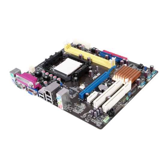
Page 16: Motherboard Layout
CPU_FAN LAN1_USB12 AUDIO M2N68 PLUS PCIEX1_1 Realtek PCIEX16 8211CL Lithium Cell CMOS Power PCIEX1_2 SB_PWR NVIDIA ® MCP68 SE PCI1 SATA4 SATA3 PCI2 SATA2 SATA1 BIOS PCI3 CLRTC PRI_IDE SPEAKER PCI4 USB56 USB78 USB910 F_PANEL SPDIF_OUT AAFP ASUS M2N68 PLUS... -
Page 17: Layout Contents
1.5.4 Layout contents Connectors/Jumpers/Slots Page Connectors/Jumpers/Slots Page ATX power connectors (24-pin EATXPWR, 1-21 System panel connector (10-1 pin F_PANEL) 1-23 4-pin ATX12V) DDR2 DIMM slots 1-10 USB connectors (10-1 pin USB56, USB78, 1-20 USB910) CPU Socket 10. Speaker connector (4-pin SPEAKER) 1-17 CPU fan connector (4-pin CPU_FAN) 1-22... - Page 18 Connect the CPU fan cable to the CPU_FAN connector on the motherboard. Do not forget to connect the CPU fan connector! Hardware monitoring errors can occur if you fail to plug this connector. ASUS M2N68 PLUS...
-
Page 19: Installing The Heatsink And Fan
1.6.2 Installing the heatsink and fan Make sure that you use only AMD-certified heatsink and fan assembly. Follow these steps to install the CPU heatsink and fan. Place the heatsink on top of the installed CPU, making sure that the heatsink fits properly on the retention module base. -
Page 20: System Memory
240-pin footprint compared to the 184-pin DDR DIMM. DDR2 DIMMs are notched differently to prevent installation on a DDR DIMM socket. The figure illustrates the location of the DDR2 DIMM sockets: Channel Sockets Channel A DIMM_A1 Channel B DIMM_B1 1-10 ASUS M2N68 PLUS... -
Page 21: Memory Configurations
The motherboard supports up to 8GB memory modules on Windows XP Professional x64 ® and Vista x64 editions. You may install a maximum of 4GB DIMMs on each slot. M2N68 PLUS Motherboard Qualified Vendors Lists (QVL) DDR2-667MHz capability DIMM support Chip Vendor Part No. - Page 22 • A*: Supports one module inserted into either slot as the single-channel memory configuration. • B*: Supports one pair of modules inserted into both the yellow slots as one pair of dual-channel memory configuration. Visit the ASUS website at www.asus.com for the latest QVL. 1-12 ASUS M2N68 PLUS...
-
Page 23: Installing A Dimm
1.7.3 Installing a DIMM Unplug the power supply before adding or removing DIMMs or other system components. Failure to do so can cause severe damage to both the motherboard and the components. Unlock a DDR2 DIMM socket by DDR2 DIMM notch pressing the retaining clips outward. -
Page 24: Expansion Slots
This motherboard supports PCI Express x1 network cards, SCSI cards and other cards that comply with the PCI Express specifications. 1.8.5 PCI Express x16 slot This motherboard supports a PCI Express x16 graphics card that complies with the PCI Express specifications. 1-14 ASUS M2N68 PLUS... -
Page 25: Jumpers
Jumpers Clear RTC RAM (3-pin CLRTC) This jumper allows you to clear the Real Time Clock (RTC) RAM in CMOS. You can clear the CMOS memory of date, time, and system setup parameters by erasing the CMOS RTC RAM data. The onboard button cell battery powers the RAM data in CMOS, which include system setup information such as system passwords. -
Page 26: Connectors
Ensure that the audio device of Sound playback is Realtek High Definition Audio (the name may be different based on the OS). Go to Start > Control Panel > Sounds and Audio Devices > Sound Playback to configure the setting. 1-16 ASUS M2N68 PLUS... -
Page 27: Internal Connectors
USB 2.0 ports 1 and 2. These two 4-pin Universal Serial Bus (USB) ports are available for connecting USB 2.0 devices. USB 2.0 ports 3 and 4. These two 4-pin Universal Serial Bus (USB) ports are available for connecting USB 2.0 devices. COM port. - Page 28 This prevents incorrect insertion when you connect the IDE cable. • Use the 80-conductor IDE cable for Ultra DMA 133/100/66 IDE devices. If any device jumper is set as “Cable-Select”, ensure that all other device jumpers have the same setting. 1-18 ASUS M2N68 PLUS...
- Page 29 Serial ATA connectors (7-pin SATA1, SATA2, SATA3, SATA4) These connectors are for the Serial ATA signal cables for Serial ATA 3Gb/s hard disk and optical disk drives. The Serial ATA 3Gb/s is backward compatible with Serial ATA 1.5Gb/s specification. The data transfer rate of the Serial ATA 3Gb/s is faster than the standard parallel ATA with 133 MB/s (Ultra DMA133).
- Page 30 • By default, this connector is set to [HD Audio]. If you want to connect a High Definition front panel audio module to this connector, set the Front Panel Select item in the BIOS to [HD Audio]. See section “2.4.3 Chipset” for details. 1-20 ASUS M2N68 PLUS...
- Page 31 The system may become unstable or may not boot up if the power is inadequate. • If you are uncertain about the minimum power supply requirement for your system, refer to the Recommended Power Supply Wattage Calculator at http://support.asus. com/PowerSupplyCalculator/PSCalculator.aspx?SLanguage=en-us for details. Chapter 1: Product introduction...
- Page 32 These are not jumpers! Do not place jumper caps on the fan connectors! Only the CPU fan supports the ASUS Q-Fan feature. Digital audio connector (4-1 pin SPDIF_OUT) This connector is for an additional Sony/Philips Digital Interface (S/PDIF) port(s).
- Page 33 M2N68 PLUS PIN 1 +HD_LED RESET M2N68 PLUS System panel connector System power LED (2-pin PWRLED) • This 2-pin connector is for the system power LED. Connect the chassis power LED cable to this connector. The system power LED lights up when you turn on the system power, and blinks when the system is in sleep mode.
-
Page 34: Software Support
The contents of the Support DVD are subject to change at any time without notice. Visit the ASUS website at www.asus.com for updates. To run the Support DVD Place the Support DVD to the optical drive. -
Page 35: Bios Information
BIOS in the future. Copy the original motherboard BIOS using the ASUS Update or AFUDOS utilities. 2.1.1 ASUS Update utility The ASUS Update is a utility that allows you to manage, save, and update the motherboard BIOS in Windows environment. ®... -
Page 36: Asus Ez Flash 2 Utility
2.1.2 ASUS EZ Flash 2 utility The ASUS EZ Flash 2 feature allows you to update the BIOS without having to use an OS-based utility. Before using this utility, download the latest BIOS file from the ASUS website at www.asus. -
Page 37: Asus Crashfree Bios 3 Utility
2.1.3 ASUS CrashFree BIOS 3 utility The ASUS CrashFree BIOS 3 is an auto recovery tool that allows you to restore the BIOS file when it fails or gets corrupted during the updating process. You can update a corrupted BIOS file using the motherboard support DVD or a USB flash disk that contains the updated BIOS file. -
Page 38: Bios Setup Program
• The BIOS setup screens shown in this section are for reference purposes only, and may not exactly match what you see on your screen. • Visit the ASUS website at www.asus.com to download the latest BIOS file for this motherboard. -
Page 39: Bios Menu Screen
• The BIOS setup screens shown in this chapter are for reference purposes only, and may not exactly match what you see on your screen. • Visit the ASUS website at www.asus.com to download the latest BIOS information. Chapter 2: BIOS information... -
Page 40: Navigation Keys
(C)Copyright 1985-2008, A m e r i c a n Megatrends, Inc. Pop-up window Press the Scroll bar <Up> / <Down> arrow keys or <Page Up> /<Page Down> keys to display the other items on the screen. ASUS M2N68 PLUS... -
Page 41: Main Menu
Main menu When you enter the BIOS Setup program, the Main menu screen appears, giving you an overview of the basic system information. Refer to section “2.2.1 BIOS menu screen” for information on the menu screen items and how to navigate through them. BIOS SETUP UTILITY Main Advanced... -
Page 42: Primary Ide Master/Slave And Sata 1~4
Selects the DMA mode. Configuration options: [Auto] SMART Monitoring [Auto] Sets the Smart Monitoring, Analysis, and Reporting Technology. Configuration options: [Auto] [Disabled] [Enabled] 32Bit Data Transfer [Enabled] Enables or disables 32-bit data transfer. Configuration options: [Disabled] [Enabled] ASUS M2N68 PLUS... -
Page 43: System Information
2.3.5 System Information This menu gives you an overview of the general system specifications. The BIOS automatically detects the items in this menu. AMI BIOS Displays the auto-detected BIOS information. Processor Displays the auto-detected CPU specification. System Memory Displays the auto-detected system memory. Advanced menu The Advanced menu items allow you to change the settings for the CPU and other system devices. - Page 44 Memclock Value [200 MHz] Allows you to set the Memclock value. Configuration options: [200 MHz] [266 MHz [333 MHz] [400 MHz] DRAM Timing Mode [Auto] Allows you to set the DRAM timing mode. Configuration options: [Auto] [DCT 0] 2-10 ASUS M2N68 PLUS...
- Page 45 The following items appear only when the DRAM Timing Mode item is set to [DCT0]. CAS Latency (CL) [Auto] Allows you to set CAS# latency. Configuration options: [Auto] [3 CLK] [4 CLK] [5 CLK] [6 CLK] [7 CLK DH_Only] TRCD [Auto] Allows you to set TRCD.
-
Page 46: Cpu Configuration
Configuration options: [Disabled] [Address bits 6] [Address bits 12] [XOR of Address bits [20:16,6] ] [XOR of Address bits [20:16,9] ] Enable Clock to All DIMMs [Disabled] Enables or disables clock to all DIMMs. Configuration options: [Disabled] [Enabled] 2-12 ASUS M2N68 PLUS... -
Page 47: Onboard Devices Configuration
MemClk Tristate C3/ATLVID [Disabled] Enables or disables the MemClk Tristate C3/ALTVID. Configuration options: [Disabled] [Enabled] Memory Hole Remapping [Enabled] Enables or disables the memory remapping around memory hole. Configuration options: [Disabled] [Enabled] DCT Unganged Mode [Auto] Allows you to enable or disable Unganed mode. Configuration options: [Auto] [Always] Power Down Enable [Enabled] Enables or disables the DDR power down mode. -
Page 48: Pci Pnp
USB support is disabled. Configuration options: [Disabled] [Enabled] [Auto] USB 2.0 Controller Mode [HiSpeed] Allows you to configure the USB 2.0 controller in HiSpeed (480 Mbps) or Full Speed (12 Mbps). Configuration options: [FullSpeed] [HiSpeed] 2-14 ASUS M2N68 PLUS... -
Page 49: Power Menu
Power menu The Power menu items allow you to change the settings for the Advanced Configuration and Power Interface (ACPI) and the Advanced Power Management (APM). Select an item then press <Enter> to display the configuration options. Suspend Mode [Auto] Select the ACPI state ACPI 2.0 Support [Disabled]... -
Page 50: Hardware Monitor
Smart Q-Fan Function [Disabled] Allows you to enable or disable the ASUS Q-Fan feature that smartly adjusts the fan speeds for more efficient system operation. Configuration options: [Disabled] [Enabled] The following items appear only when the Smart Q-Fan Function is set to [Enabled] Fan Auto Mode Start Voltage [5.0V]... -
Page 51: Boot Menu
This allows you to enable or disable the full screen logo display feature. Configuration options: [Disabled] [Enabled] Set this item to [Enabled] to use the ASUS MyLogo 2™ feature. AddOn ROM Display Mode [Force BIOS] Sets the display mode for option ROM. Configuration options: [Force BIOS] [Keep Current] Bootup Num-Lock [On] Allows you to select the power-on state for the NumLock. -
Page 52: Security
View Only allows access but does not allow change to any field. Limited allows changes only to selected fields, such as Date and Time. Full Access allows viewing and changing all the fields in the Setup utility. 2-18 ASUS M2N68 PLUS... -
Page 53: Tools Menu
1.NTFS format 2.7.1 ASUS EZ Flash 2 Allows you to run ASUS EZ Flash 2. When you press <OK>, a confirmation message appears. Use the left/right arrow key to select between [Yes] or [No], then press <OK> to confirm your choice. -
Page 54: Exit Menu
When you select this option or if you press <F5>, a confirmation window appears. Select OK to load default values. Select Exit & Save Changes or make other changes before saving the values to the non-volatile RAM. 2-20 ASUS M2N68 PLUS...