Table of Contents
Advertisement
Advertisement
Table of Contents

Related Manuals for Asus M2N68 AM - Motherboard - Micro ATX


Summary of Contents for Asus M2N68 AM - Motherboard - Micro ATX
- Page 1 M2N68-AM...
- Page 2 Product warranty or service will not be extended if: (1) the product is repaired, modified or altered, unless such repair, modification of alteration is authorized in writing by ASUS; or (2) the serial number of the product is defaced or missing.
-
Page 3: Table Of Contents
Welcome! ..................1-1 Package contents ................. 1-1 Special features ................1-1 1.3.1 Product highlights ............1-1 1.3.2 Innovative ASUS features ..........1-3 Before you proceed ..............1-4 Motherboard overview ..............1-5 1.5.1 Placement direction ............1-5 1.5.2 Screw holes ..............1-5 1.5.3... - Page 4 2.1.1 Creating a bootable floppy disk ........2-1 2.1.2 ASUS Update utility ............2-2 2.1.3 ASUS EZ Flash 2 utility ........... 2-3 2.1.4 AFUDOS utility ..............2-4 2.1.5 ASUS CrashFree BIOS 3 utility ........2-5 BIOS setup program ..............2-6 2.2.1...
- Page 5 Boot menu .................. 2-20 2.6.1 Boot Device Priority ............2-20 2.6.2 Boot Settings Configuration .......... 2-20 2.6.3 Security ................. 2-21 Tools menu ................. 2-23 2.7.1 ASUS EZ Flash 2 ............2-23 2.7.2 AI NET 2................ 2-23 Exit menu ..................2-24...
-
Page 6: Notices
Notices Federal Communications Commission Statement This device complies with Part 15 of the FCC Rules. Operation is subject to the following two conditions: • This device may not cause harmful interference, and • This device must accept any interference received including interference that may cause undesired operation. -
Page 7: Safety Information
Safety information Electrical safety • To prevent electric shock hazard, disconnect the power cable from the electric outlet before relocating the system. • When adding or removing devices to or from the system, ensure that the power cables for the devices are unplugged before the signal cables are connected. If possible, disconnect all power cables from the existing system before you add a device. -
Page 8: Conventions Used In This Guide
Refer to the following sources for additional information and for product and software updates. ASUS websites The ASUS website provides updated information on ASUS hardware and software products. Refer to the ASUS contact information. Optional documentation Your product package may include optional documentation, such as warranty flyers, that may have been added by your dealer. -
Page 9: M2N68-Am Specifications Summary
M2N68-AM specifications summary AMD socket AM2/AM2+ for AMD Phenom™ FX / Phenom™ / Athlon™ / Sempron™ processors AMD64 architecture enables simultaneous 32-bit and 64-bit computing Supports AMD Cool ‘n’ Quiet™ Technology Chipset MCP68S/MCP68PVNT System bus 2000 / 1600 MT/s Memory Dual-channel memory architecture 2 x 240-pin DIMM sockets support up to 4GB of unbufferred ECC and non-ECC 1066 / 800 / 667 / 533 MHz DDR2 memory... - Page 10 Manageability WfM2.0, DMI2.0, WOR by Ring, PME Wake Up, PXE WO_USB, WO_KB/MS ASUS Special Features ASUS Q-Fan ASUS CrashFree BIOS 3 ASUS EZ Flash 2 ASUS MyLogo 2 Rear panel ports 1 x LAN (RJ-45) port 1 x COM port...
-
Page 11: Chapter 1: Product Introduction
® The motherboard delivers a host of new features and latest technologies, making it another standout in the long line of ASUS quality motherboards! Before you start installing the motherboard, and hardware devices on it, check the items in your package with the list below. - Page 12 5, RAID 10, and JBOD configurations for Serial ATA drives. Gigabit LAN solution The on-board LAN controller is a highly integrated Gb LAN controller. It is enhanced with an ACPI management function to provide efficient power management for advanced operating systems. ASUS M2N68-AM...
-
Page 13: Innovative Asus Features
BIOS file using the bundled support DVD or USB flash disk that contains the latest BIOS file. ASUS EZ Flash 2 ASUS EZ Flash 2 is a utility that allows you to update the BIOS without using an OS-based utility. CPU Parameter Recall (C.P.R) The BIOS C.P.R. -
Page 14: Before You Proceed
ON, in sleep mode, or in soft-off mode. This is a reminder that you should shut down the system and unplug the power cable before removing or plugging in any motherboard component. The illustration below shows the location of the onboard LED. SB_PWR M2N68-AM Standby Power Powered Off M2N68-AM Onboard LED ASUS M2N68-AM... -
Page 15: Motherboard Overview
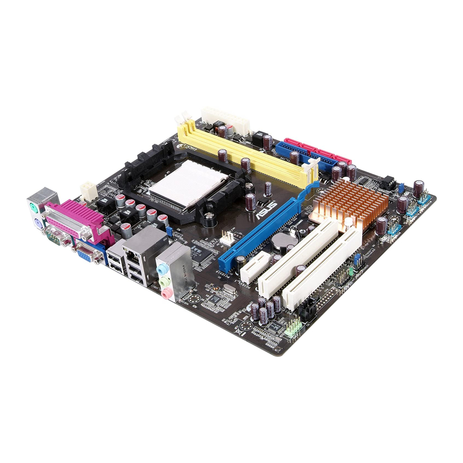
Motherboard overview 1.5.1 Placement direction When installing the motherboard, ensure that you place it into the chassis in the correct orientation. The edge with external ports goes to the rear part of the chassis as indicated in the image below. 1.5.2 Screw holes Place six screws into the holes indicated by circles to secure the motherboard to the chassis. -
Page 16: Motherboard Layout
Clear RTC RAM (3-pin CLRTC) 1-18 14. PCIe x16/PCIe x1/PCI slot 1-17 Internal speaker connector (4-pin SPEAKER) 1-25 15. Digital audio connector (4-1 pin SPDIF_OUT) 1-23 Standby power LED (SB_PWR) 16. Floppy disk drive connector (34-1 pin FLOPPY) 1-20 ASUS M2N68-AM... -
Page 17: Central Processing Unit (Cpu)
Central Processing Unit (CPU) The motherboard comes with an AM2 / AM2+ socket designed for AMD Phenom™ FX / ® Phenom / Athlon™ / Sempron™ processor. The AM2/AM2+ socket has a different pinout from the 940-pin socket designed for the AMD Opteron™... - Page 18 Connect the CPU fan cable to the CPU_FAN connector on the motherboard. CPU_FAN M2N68-AM M2N68-AM CPU fan connector Do not forget to connect the CPU fan connector! Hardware monitoring errors can occur if you fail to plug this connector. ASUS M2N68-AM...
-
Page 19: Installing The Heatsink And Fan
1.6.2 Installing the heatsink and fan Ensure that you use only AMD-certified heatsink and fan assembly. To install the CPU heatsink and fan: Place the heatsink on top of the installed CPU, making sure that the heatsink fits properly on the retention module base. •... -
Page 20: System Memory
240-pin footprint compared to the 184-pin DDR DIMM. DDR2 DIMMs are notched differently to prevent installation on a DDR DIMM socket. The figure illustrates the location of the DDR2 DIMM sockets: Channel Sockets Channel A DIMM_A1 Channel B DIMM_B1 M2N68-AM M2N68-AM 240-pin DDR2 DIMM sockets 1-10 ASUS M2N68-AM... -
Page 21: Memory Configurations
1.7.2 Memory configurations You may install 256MB, 512MB, 1GB, and 2GB unbuffered ECC/non-ECC DDR2 DIMMs into the DIMM sockets. • You may install varying memory sizes in Channel A and Channel B. The system maps the total size of the lower-sized channel for the dual-channel configuration. Any excess memory from the higher-sized channel is then mapped for single-channel operation. - Page 22 • • HYMP512U64CP8-S5 AB Hynix HY5PS12821CFPS5 • • 512MB ADATA M20AD6G3H3160I1E58 ADATA AD29608A8A-25EG80720 • • 512MB VDATA M2GVD6G3H3160I1E53 VDATA VD29608A8A-25EG30648 • • VDATA M2GVD6G3I4170I1E53 VDATA VD29608A8A-25EG30647 • • 512MB AL6E8E63B-8E1K A3R12E3HEF641B9A05 • • AL7E8E63B-8E1K A3R12E3HEF641B9A05 • • 1-12 ASUS M2N68-AM...
- Page 23 DDR2-667MHz capability DIMM support Size Vendor Model Brand SS/DS Component 256MB Kingston KVR667D2N5/256 Kingston D3216TLSAKL3U • • 256MB Kingston KVR667D2N5/256 Infineon HYB18T256800AF3SW65 33154 • • 512MB Kingston KVR667D2N5/512 Elpida E5108AGBG-6E-E • • Kingston KVR667D2N5/1G Kingston D6408TEBGGL3U • • Kingston KVR667D2N5/1G Elpida E5108AGBG-6E-E •...
- Page 24 HY5PS121621CFP-C4 • • HYMP512U64CP8-C4 AB Hynix HY5PS12821CFP-C4 • • 512MB Micron MT 16HTF6464AG-53EB2 Micron D9BOM • • 512MB Micron MT 16HTF6464AG-53EB2 Micron Z9BQT • • Micron MT 16HTF12864AY-53EA1 Micron D9CRZ • • (continued on the next page) 1-14 ASUS M2N68-AM...
- Page 25 • A*: Supports one module inserted into any slot as Single-channel memory configuration. • B*: Supports one pair of modules inserted into both the yellow slots as one pair of Dual-channel memory configuration. Visit the ASUS website at www.asus.com for the latest QVL. Chapter 1: Product introduction 1-15...
-
Page 26: Installing A Dimm
DIMM. Support the DIMM lightly with your fingers when pressing the retaining clips. The DIMM might get damaged when it flips out with extra force. DDR2 DIMM notch Remove the DIMM from the socket. 1-16 ASUS M2N68-AM... -
Page 27: Expansion Slots
Expansion slots In the future, you may need to install expansion cards. The following sub-sections describe the slots and the expansion cards that they support. Unplug the power cord before adding or removing expansion cards. Failure to do so may cause you physical injury and damage motherboard components. -
Page 28: Jumpers
• You do not need to clear the RTC when the system hangs due to overclocking. For system failure due to overclocking, use the CPU Parameter Recall (C.P.R) feature. Shut down and reboot the system so the BIOS can automatically reset parameter settings to default values. 1-18 ASUS M2N68-AM... -
Page 29: Connectors
1.10 Connectors 1.10.1 Rear panel ports PS/2 mouse port (green). This port is for a PS/2 mouse. Parallel port. This 25-pin port connects a parallel printer, a scanner, or other devices. LAN (RJ-45) port. Supported by RTL8211CL PHY Gigabit LAN controller, this port allows Gigabit connection to a Local Area Network (LAN) through a network hub. -
Page 30: Internal Connectors
• Pin 5 on the connector is removed to prevent incorrect cable connection when using an FDD cable with a covered Pin 5. • The FDD cable is purchased separately. FLOPPY M2N68-AM PIN1 NOTE:Orient the red markings on the floppy ribbon cable to PIN 1. M2N68-AM Floppy disk drive connector 1-20 ASUS M2N68-AM... - Page 31 IDE connectors (40-1 pin PRI_IDE) The onboard IDE connector is for an Ultra DMA 133/100/66 signal cable. There are three connectors on each Ultra DMA 133/100/66 signal cable: blue, black, and gray. Connect the blue connector to the motherboard’s IDE connector, then select one of the following modes to configure your devices.
- Page 32 For detailed instructions on how to configure RAID 0, RAID 1, RAID 5, RAID 10, and JBOD, refer to the RAID manual in the Support DVD. Serial ATA hard disk drive connection Connector Color Setting SATA1/2 Master Boot disk SATA3/4 Slave Data disk 1-22 ASUS M2N68-AM...
- Page 33 CPU fan connector (4-pin CPU_FAN) The CPU fan connector supports cooling fans of 350mA~740mA (8.88W max.) or a total of 1A~2.22A (26.64W max.) at +12V. Connect the CPU fan cable to the CPU fan connector on the motherboard, ensuring that the black wire of the cable matches the ground pin of the connector.
- Page 34 The USB 2.0 module is purchased separately. Optical drive audio in connector (4-pin CD) These connectors allow you to receive stereo audio input from sound sources such as a CD-ROM, TV tuner, or MPEG card. M2N68-AM M2N68-AM Internal audio connector 1-24 ASUS M2N68-AM...
- Page 35 Front panel audio connector (10-1 pin AAFP) This connector is for a chassis-mounted front panel audio I/O module that supports either High Definition Audio or AC`97 audio standard. Connect one end of the front panel audio I/O module cable to this connector. AAFP PIN 1 PIN 1...
- Page 36 The system may become unstable or may not boot up if the power is inadequate. • If you are uncertain about the minimum power supply requirement for your system, refer to the Recommended Power Supply Wattage Calculator at http://support.asus. com/PowerSupplyCalculator/PSCalculator.aspx?SLanguage=en-us for details. 1-26...
-
Page 37: System Panel Connector 10-1 Pin F_Panel
System panel connector (10-1 pin F_PANEL) This connector supports several chassis-mounted functions. PWR LED PWR BTN F_PANEL PIN 1 M2N68-AM HD_LED RESET M2N68-AM System panel connector • System power LED (2-pin PLED) This 2-pin connector is for the system power LED. Connect the chassis power LED cable to this connector. -
Page 38: Software Support
The contents of the Support DVD are subject to change at any time without notice. Visit the ASUS website at www.asus.com for updates. To run the Support DVD Place the Support DVD into the optical drive. -
Page 39: Chapter 2: Bios Information
Save a copy of the original motherboard BIOS file to a floppy disk or a USB flash disk in case you need to restore the BIOS in the future. Copy the original motherboard BIOS using the ASUS Update or AFUDOS utilities. 2.1.1 Creating a bootable floppy disk Create a bootable floppy disk using a different computer. -
Page 40: Asus Update Utility
2.1.2 ASUS Update utility The ASUS Update is a utility that allows you to manage, save, and update the motherboard BIOS in Windows environment. ® • ASUS Update requires an Internet connection either through a network or an Internet Service Provider (ISP). -
Page 41: Asus Ez Flash 2 Utility
2.1.3 ASUS EZ Flash 2 utility The ASUS EZ Flash 2 feature allows you to update the BIOS without using an OS-based utility. Before you start using this utility, download the latest BIOS file from the ASUS website at www.asus.com. -
Page 42: Afudos Utility
• Obtain the AFUDOS utility (afudos.exe) from the bundled support DVD and the latest BIOS file from the ASUS website at www.asus.com. • We recommend that you write the BIOS filename on a piece of paper. You will need to key in the exact BIOS filename at the DOS prompt later. -
Page 43: Asus Crashfree Bios 3 Utility
2.1.5 ASUS CrashFree BIOS 3 utility The ASUS CrashFree BIOS 3 is an auto recovery tool that allows you to restore the BIOS file when it fails or gets corrupted during the updating process. You can update a corrupted BIOS file using the motherboard support DVD, a floppy disk, or a USB flash disk that contains the updated BIOS file. -
Page 44: Bios Setup Program
• The BIOS setup screens shown in this section are for reference only, and may not exactly match what you see on your screen. • Visit the ASUS website at www.asus.com to download the latest BIOS file for this motherboard. -
Page 45: Bios Menu Screen
• The BIOS setup screens shown in this chapter are for reference purposes only, and may not exactly match what you see on your screen. • Visit the ASUS website at www.asus.com to download the latest BIOS information. ASUS M2N68-AM... -
Page 46: Navigation Keys
2.2.3 Navigation keys At the bottom right corner of a menu screen are the navigation keys for that particular menu. Use the navigation keys to select items in the menu and change the settings. Some of the navigation keys differ from one screen to another. 2.2.4 Menu items The highlighted item on the menu bar displays the specific items for that menu. -
Page 47: Main Menu
Allows you to enable or disable the onboard IDE controller. Configuration options: [Enabled] [Disabled] Serial-ATA Devices [Enabled] Allows you to disable or set the Serial-ATA devices. Configuration options: [Enabled] [Disabled] SATA Mode select [SATA Mode] Allows you to select the SATA Mode. Configuration options: [SATA Mode] [RAID Mode] ASUS M2N68-AM... -
Page 48: Primary Ide Master/Slave
The following two items appear only when the SATA Mode select item is set to [RAID Mode]. SATA1/SATA2 [Disabled] Allows you to disable or enable the SATA1/SATA2. Configuration options: [Enabled] [Disabled] SATA3/SATA4 [Disabled] Allows you to disable or enable the SATA3/SATA4. Configuration options: [Enabled] [Disabled] 2.3.5 Primary IDE Master/Slave... -
Page 49: Sata1~4
This features allows your system to report read/write errors of the hard drive and to issue warnings when a third party hardware monitor utility is installed. Configuration options: [Auto] [Disabled] [Enabled] 32Bit Data Transfer [Enabled] Enables or disables 32-bit data transfer. Configuration options: [Disabled] [Enabled] ASUS M2N68-AM 2-11... -
Page 50: System Information
2.3.7 System Information This menu gives you an overview of the general system specifications. The BIOS automatically detects the items in this menu. AMI BIOS Displays the auto-detected BIOS information Processor Displays the auto-detected CPU specification System Memory Displays the auto-detected system memory Advanced menu The Advanced menu items allow you to change the settings for the CPU and other system devices. - Page 51 Allows you to select the Processor voltage or set it to auto for safe mode. Configuration options: [Auto] [+ 50mv] [+100mv] [+ 150mv] Memory Clock Mode [Auto] Allows you to set the memory clock mode. Configuration options: [Auto] [Manual] ASUS M2N68-AM 2-13...
-
Page 52: Cpu Configuration
The following item appears only when the Memory clock mode item is set to [Manual]. Memclock Value [200 MHz] Allows you to set the Memclock value. Configuration options: [200 MHz] [266 MHz] [333 MHz] [400 MHz] [533 MHz] DRAM Timing Mode [Auto] Allows you to set the DRAM timing mode. -
Page 53: Ecc Configuration
Disables or sets the Data/L2/L3 Cache BG Scrub. This item allows the cache RAM to be corrected when idle. Configuration options: [Disabled] [40ns] [80ns] [160ns] [320ns] [640ns] [1.28us] [2.56us] [5.12us] [10.2us] [20.5us] [41.0us] [81.9us] [163.8us] [327.7us] [655.4us] ASUS M2N68-AM 2-15... -
Page 54: Onboard Devices Configuration
SouthBridge Configuration Primary Graphics Adapter [PCIE-> PCI -> IGP] Display Device Priority, from high to low. Configuration options: [PCIE-> PCI-> IGP] [IGP ->PCI -> PCIE] iGPU Frame Buffer Detect [Auto] Allows you to set the iGPU Frame Buffer Detect. Configuration options: [Disabled] [Auto] iGPU Frame Buffer Size [128MB] Allows you to set the iGPU Frame Buffer Size. -
Page 55: Pci Pnp
The Module Version and USB Devices Enabled items show the auto-detected values. If no USB device is detected, the item shows None. USB Functions [Enabled] Enables or disables the USB Functions. Configuration options: [Disabled] [Enabled] USB 2.0 Controller [Enabled] Enables or disables the USB 2.0 Controller. Configuration options: [Disabled] [Enabled] ASUS M2N68-AM 2-17... -
Page 56: Power Menu
Legacy USB Support [Auto] Allows you to enable or disable support for Legacy USB storage devices, including USB flash drives and USB hard drives. Setting to Auto allows the system to detect the presence of USB devices at startup. If detected, the USB controller legacy mode is enabled. If no USB device is detected, the legacy USB support is disabled. -
Page 57: Apm Configuration
The onboard hardware monitor automatically detects the voltage output through the onboard voltage regulators. Smart Q-Fan Function [Disabled] Allows you to enable or disable the ASUS Q-Fan feature that smartly adjusts the fan speeds for more efficient system operation. Configuration options: [Disabled] [Enabled] ASUS M2N68-AM... -
Page 58: Boot Menu
POST items. Configuration options: [Disabled] [Enabled] Full Screen Logo [Enabled] This allows you to enable or disable the full screen logo display feature. Configuration options: [Disabled] [Enabled] Set this item to [Enabled] to use the ASUS MyLogo 2™ feature. 2-20 Chapter 2: BIOS setup... -
Page 59: Security
<Enter>. The message “Password Uninstalled” appears. If you forget your BIOS password, you can clear clear it by erasing the CMOS Real Time Clock (RTC) RAM. See section “1.9 Jumper” for information on how to erase the RTC RAM. ASUS M2N68-AM 2-21... -
Page 60: Change User Password
After you have set a supervisor password, the other items appear to allow you to change other security settings. User Access Level [Full Access] This item allows you to select the access restriction to the Setup items. Configuration options: [No Access] [View Only] [Limited] [Full Access] No Access - prevents user access to the Setup utility. -
Page 61: Tools Menu
1. NTFS format 2.7.1 ASUS EZ Flash 2 Allows you to run ASUS EZ Flash 2. When you press <Ok>, a confirmation message appears. Use the left/right arrow key to select between [Yes] or [No], then press <Ok> to confirm your choice. -
Page 62: Exit Menu
Exit menu The Exit menu items allow you to load the optimal or failsafe default values for the BIOS items, and save or discard your changes to the BIOS items. Exit Options Exit system setup after saving the Exit & Save Changes changes.