Table of Contents
Advertisement
Advertisement
Table of Contents

Related Manuals for Asus F2A55-M/CSM


Summary of Contents for Asus F2A55-M/CSM
- Page 1 F2A55-M...
- Page 2 Product warranty or service will not be extended if: (1) the product is repaired, modified or altered, unless such repair, modification of alteration is authorized in writing by ASUS; or (2) the serial number of the product is defaced or missing.
-
Page 3: Table Of Contents
Special features .................... 1-1 1.1.1 Product highlights ................1-1 1.1.2 DIGI+VRM ..................1-2 1.1.3 Innovative ASUS features ............... 1-2 1.1.4 ASUS Quiet Thermal Solution............1-3 1.1.5 ASUS EZ DIY .................. 1-3 Before you proceed ..................1-4 Motherboard overview ................. 1-5 1.3.1... - Page 4 Managing and updating your BIOS ............. 2-1 2.1.1 ASUS Update utility ................ 2-1 2.1.2 ASUS EZ Flash 2 ................2-2 2.1.3 ASUS CrashFree BIOS 3 utility ............2-3 2.1.4 ASUS BIOS Updater ............... 2-4 BIOS setup program ..................2-6 Main menu ....................2-10 2.3.1 System Language [English] ............
- Page 5 2.7.11 Boot Option Priorities ..............2-29 2.7.12 Boot Override ................2-29 Tools menu ....................2-30 2.8.1 ASUS EZ Flash 2 Utility ..............2-30 2.8.2 ASUS SPD Information ..............2-30 2.8.3 ASUS O.C. Profile ................. 2-30 Exit menu ....................2-31 Appendices Notices ........................
-
Page 6: Safety Information
Safety information Electrical safety • To prevent electrical shock hazard, disconnect the power cable from the electrical outlet before relocating the system. • When adding or removing devices to or from the system, ensure that the power cables for the devices are unplugged before the signal cables are connected. If possible, disconnect all power cables from the existing system before you add a device. -
Page 7: About This Guide
Refer to the following sources for additional information and for product and software updates. ASUS websites The ASUS website provides updated information on ASUS hardware and software products. Refer to the ASUS contact information. Optional documentation Your product package may include optional documentation, such as warranty flyers, that may have been added by your dealer. -
Page 8: Conventions Used In This Guide
Conventions used in this guide To ensure that you perform certain tasks properly, take note of the following symbols used throughout this manual. DANGER/WARNING: Information to prevent injury to yourself when trying to complete a task. CAUTION: Information to prevent damage to the components when trying to complete a task IMPORTANT: Instructions that you MUST follow to complete a task. -
Page 9: F2A55-M Specifications Summary
3GB is recommended. ** The Max. 64GB memory capacity can be supported with DIMMs of 8GB (or above). ASUS will update QVL once the DIMMs are available on the market. *** Refer to www.asus.com for the latest Memory QVL (Qualified Vendors List). - Page 10 - ASUS Fanless Design: Stylish heatsink solution - ASUS Fan Xpert ASUS EZ DIY - ASUS UEFI BIOS EZ Mode featuring friendly graphics user interface - ASUS CrashFree BIOS 3 - ASUS EZ Flash 2 - ASUS My Logo 2...
- Page 11 BIOS features 64 Mb Flash ROM, UEFI AMI BIOS, PnP, DMI 2.0, WfM 2.0, SM BIOS 2.7, ACPI v2.0a, Multi-language BIOS, ASUS EZ Flash 2, ASUS CrashFreen BIOS 3, F12 Printscreen function, F3 Shortcut function, and ASUS DRAM SPD (Serial Presence Detect) memory information...
-
Page 12: Package Contents
887-VD2 SPDIF_OUT USB910 USB78 USB56 CLRTC PANEL AAFP ASUS F2A55-M motherboard 2 x Serial ATA 3.0 Gb/s cables 1 x I/O-Shield User Guide Support DVD • If any of the above items is damaged or missing, contact your retailer. •... -
Page 13: Product Introduction
CrossFireX™ allows higher antialiasing, anisotropic filtering, shading, and texture settings. Adjust your display configurations, experiment with the advanced 3D settings, and check the effects with a real- time 3D-rendered previews within AMD Catalyst™ Control Center. ASUS F2A55-M... -
Page 14: Digi+Vrm
ASUS TurboV With its user-friendly interface, ASUS TurboV offers you the adrenaline rush of real-time overclocking without exiting or rebooting the OS. It also provides you with the ASUS OC profiles for the best overclocking settings in different scenarios. MemOK! -
Page 15: Asus Quiet Thermal Solution
Ai Charger+ ASUS Ai Charger+, the latest Ai Charger* version, brings you to a new level of USB3.0 fast charging experience. With its easy and user-friendly interface, you can easily charge iPod, iPhone, iPad, but also BC 1.1** standard mobile devices three times*** as fast as before. -
Page 16: Asus Mylogo2
DVD or USB flash disk that contains the latest BIOS file. ASUS EZ Flash 2 ASUS EZ Flash 2 is a utility that allows you to update the BIOS without using an OS-based utility. C.P.R. (CPU Parameter Recall) The BIOS C.P.R. -
Page 17: Motherboard Overview
Screw holes Place eight screws into the holes indicated by circles to secure the motherboard to the chassis. Do not overtighten the screws! Doing so can damage the motherboard. Place this side towards the rear of the chassis F2A55-M ASUS F2A55-M... -
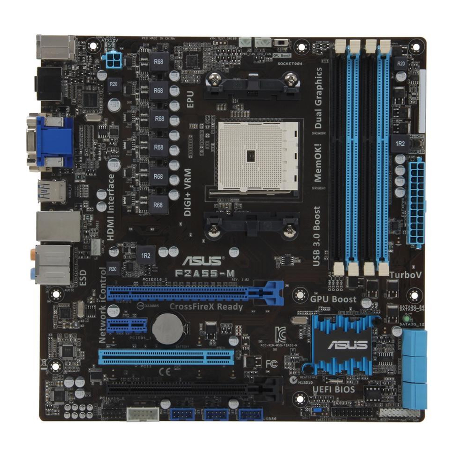
Page 18: Motherboard Layout
1.3.3 Motherboard layout 24.4cm(9.6in) GPU Boost PWR_FAN KBMS_USB34 CPU_FAN GPU_LED DIGI+ ATX12V SPDIFO _HDMI USB3_12 LAN_USB12 CHA_FAN AUDIO F2A55-M PCIEX16_1 8111F SB_PWR PCIEX1_1 Lithium Cell CMOS Power ® Super PCI1 PCIEX16_2 64Mb BIOS 887-VD2 SPDIF_OUT CLRTC USB910 USB78 USB56 PANEL AAFP Chapter 1: Product introduction... -
Page 19: Layout Contents
F2A55-M CPU socket FM2 Ensure that you use a APU designed for the FM2 socket. The APU fits in only one correct orientation. DO NOT force the APU into the socket to prevent bending the pins and damaging the APU! ASUS F2A55-M... -
Page 20: Installing The Apu
1.4.1 Installing the APU Chapter 1: Product introduction... -
Page 21: Apu Heatsink And Fan Assembly Installation
1.4.2 APU heatsink and fan assembly installation Apply the Thermal Interface Material to the APU heatsink and APU before you install the heatsink and fan if necessary. To install the APU heatsink and fan assembly ASUS F2A55-M... - Page 22 To uninstall the APU heatsink and fan assembly 1-10 Chapter 1: Product introduction...
-
Page 23: System Memory
DDR2 DIMM socket. DDR3 modules are developed for better performance with less power consumption. The figure illustrates the location of the DDR3 DIMM sockets: Channel Sockets Channel A DIMM_A1 and DIMM_A2 Channel B DIMM_B1 and DIMM_B2 F2A55-M F2A55-M 240-pin DDR3 DIMM sockets ASUS F2A55-M 1-11... -
Page 24: Memory Configurations
• The maximum 64GB memory capacity can be supported with 16GB or above DIMMs. ASUS will update the memory QVL once the DIMMs are available in the market. • The default memory operation frequency is dependent on its Serial Presence Detect (SPD), which is the standard way of accessing information from a memory module. - Page 25 16GB ( 4GB x4 ) DS 1.65V • • • Kingston KHX1866C9D3T1K3/6GX(XMP) 6GB(3 x 2GB) 1.65V • • • Kingston KHX1866C11D3P1K2/8G 8GB ( 4GB x 2) 1.5V • • • Kingston KHX1866C9D3K2/8GX(XMP) 8GB(4GBX2) 1.65V • • • ASUS F2A55-M 1-13...
- Page 26 DDR3-1600 MHz capability DIMM socket support Chip (Optional) Vendors Part No. Size Chip NO. Timing Voltage Brand 1 DIMM 2 DIMMs 4 DIMMs A-DATA 3CCD-1509 A-DATA AM2U16BC2P1 • • • A EL1126T A-DATA AX3U1600XB2G79-2X(XMP) 4GB(2 x 2GB) 7-9-7-21 1.55V-1.75V • •...
- Page 27 Corsair 9-9-9-24 - • • • 01136 Corsair CMX4GX3M1A1333C9 9-9-9-24 1.50V • • • Corsair CMD8GX3M4A1333C7 8GB(4 x 2GB) DS 7-7-7-20 1.60V • • • Crucial CT12864BA1339.8FF Micron 9FF22D9KPT • • • (continued on the next page) ASUS F2A55-M 1-15...
- Page 28 DDR3-1333 MHz capability DIMM socket support Chip (Optional) Vendors Part No. Size Chip NO. Timing Voltage Brand 1 DIMM 2 DIMMs 4 DIMMs Crucial CT25664BA1339.16FF DS Micron 9KF27D9KPT • • • Crucial BL25664BN1337.16FF (XMP) 6GB(3 x 2GB) DS - 7-7-7-24 1.65V •...
- Page 29 DS S-POWER 20YT3NG-1201 • • TAKEMS TMS2GB364D081-107EY DS - 7-7-7-20 1.5V • TAKEMS TMS2GB364D082-138EW DS - 8-8-8-24 1.5V • • • UMAX E41302GP0-73BDB DS UMAX U2S24D30TP-13 • • • WINTEC 3WVS31333-2G-CNR DS AMPO AM3420803-13H • • • ASUS F2A55-M 1-17...
- Page 30 A1 and B1 for better compatibility. • 4 DIMMs: Supports four (4) modules inserted into both the blue and black slots as two pairs of Dual-channel memory configuration • Visit the ASUS website at www.asus.com for the latest QVL. 1-18 Chapter 1: Product introduction...
-
Page 31: Installing A Dimm
DIMM. Support the DIMM lightly with your fingers when pressing the retaining clips. The DIMM might get damaged when it flips out with extra force. DIMM notch Remove the DIMM from the socket. ASUS F2A55-M 1-19... -
Page 32: Expansion Slots
Expansion slots In the future, you may need to install expansion cards. The following sub-sections describe the slots and the expansion cards that they support. Unplug the power cord before adding or removing expansion cards. Failure to do so may cause you physical injury and damage motherboard components. -
Page 33: Pci Express X16 Slots
PCIe x16_2 shared PCIe x1_1 shared PCI slot shared AMD FCH SATA Controller shared AMD FCH USB 1.1 shared Controller AMD FCH USB 2.0 -shared Controller ASMedia USB3.0 shared Controller HD Audio Controller shared Onboad VGA shared ASUS F2A55-M 1-21... -
Page 34: Jumpers
Jumpers Clear RTC RAM (3-pin CLRTC) This jumper allows you to clear the Real Time Clock (RTC) RAM in CMOS. You can clear the CMOS memory of date, time, and system setup parameters by erasing the CMOS RTC RAM data. The onboard button cell battery powers the RAM data in CMOS, which include system setup information such as system passwords. -
Page 35: Connectors
Line Out port (lime). This port connects a headphone or a speaker. In 4-channel, 6- channel, and 8-channel configurations, the function of this port becomes Front Speaker Out. Microphone port (pink). This port connects a microphone. ASUS F2A55-M 1-23... - Page 36 Side Speaker Out port (gray). This port connects the side speaker in an 8-channel audio configuration. Refer to the audio configuration table below for the function of the audio ports in 2, 4, 6, or 8-channel configuration. Audio 2, 4, 6, or 8-channel configuration Headset Port 4-channel...
-
Page 37: Internal Connectors
This connector is for an additional Sony/Philips Digital Interface (S/PDIF) port. Connect the S/PDIF Out module cable to this connector, then install the module to a slot opening at the back of the system chassis. F2A55-M SPDIF_OUT F2A55-M Digital audio connector The S/PDIF module is purchased separately. ASUS F2A55-M 1-25... - Page 38 • If you are uncertain about the minimum power supply requirement for your system, refer to the Recommended Power Supply Wattage Calculator at http://support.asus. com/PowerSupplyCalculator/PSCalculator.aspx?SLanguage=en-us for details. TPM connector (20-1 pin TPM) This connector supports a Trusted Platform Module (TPM) system, which securely store keys, digital certificates, passwords and data.
- Page 39 These are not jumpers! Do not place jumper caps on the fan connectors! • The CPU_FAN connector supports a CPU fan of maximum 2A (24 W) fan power. • Only the 4-pin CPU fan & CHA fan support ASUS FanXpert feature. ASUS F2A55-M 1-27...
- Page 40 USB connectors (10-1 pin USB56, USB78, USB910) These connectors are for USB 2.0 ports. Connect the USB module cable to any of these connectors, then install the module to a slot opening at the back of the system chassis. These USB connectors comply with USB 2.0 specification that supports up to 480 Mbps connection speed.
- Page 41 The Serial ATA RAID feature (RAID 0, 1, 5, and 10) is available only if you are using Windows XP SP3 or later version. ® • When using hot-plug and NCQ, set the SATA Mode Selection item in the BIOS to [AHCI]. See section 2.5.2 SATA Configuration for details. ASUS F2A55-M 1-29...
-
Page 42: System Panel Connector (20-8 Pin Panel)
System panel connector (20-8 pin PANEL) This connector supports several chassis-mounted functions. PLED SPEAKER PANEL PIN 1 F2A55-M IDE_LED PWRSW RESET * Requires an ATX power supply F2A55-M System panel connector • System power LED (2-pin PLED) This 2-pin connector is for the system power LED. Connect the chassis power LED cable to this connector. -
Page 43: Onboard Switches
BIOS default settings. A message will appear during POST reminding you that the BIOS has been restored to its default settings. • We recommend that you download and update to the latest BIOS version from the ASUS website at www.asus.com after using the MemOK! function. ASUS F2A55-M 1-31... -
Page 44: Onboard Leds
GPU Boost switch This switch allows you to enable or disable the GPU Boost function. GPU Boost F2A55-M F2A55-M GPU Boost switch 1.10 Onboard LEDs Standby Power LED The motherboard comes with a standby power LED that lights up to indicate that the system is ON, in sleep mode, or in soft-off mode. - Page 45 GPU Boost LED The GPU Boost LED lights when the GPU Boost switch is turned to Enable. GPU_LED F2A55-M F2A55-M GPU Boost LED ASUS F2A55-M 1-33...
-
Page 46: Software Support
Place the Support DVD into the optical drive. If Autorun is enabled in your computer, the DVD automatically displays the Specials screen which contains the unique features of ASUS motherboard. Click Drivers, Utilities, Make Disk, Manual, and Contact tabs to display their respective menus. -
Page 47: Bios Information
BIOS in the future. Copy the original motherboard BIOS using the ASUS Update utility. 2.1.1 ASUS Update utility The ASUS Update is a utility that allows you to manage, save, and update the motherboard BIOS in Windows environment. ®... -
Page 48: Asus Ez Flash 2
Follow the onscreen instructions to complete the updating process. 2.1.2 ASUS EZ Flash 2 The ASUS EZ Flash 2 feature allows you to update the BIOS without using an OS-based utility. Before you start using this utility, download the latest BIOS file from the ASUS website at www.asus.com. -
Page 49: Asus Crashfree Bios 3 Utility
2.1.3 ASUS CrashFree BIOS 3 utility The ASUS CrashFree BIOS 3 is an auto recovery tool that allows you to restore the BIOS file when it fails or gets corrupted during the updating process. You can restore a corrupted BIOS file using the motherboard support DVD or a USB flash drive that contains the updated BIOS file. -
Page 50: Asus Bios Updater
2.1.4 ASUS BIOS Updater The ASUS BIOS Updater allows you to update BIOS in DOS environment. This utility also allows you to copy the current BIOS file that you can use as a backup when the BIOS fails or gets corrupted during the updating process. -
Page 51: Updating The Bios File
Ensure to load the BIOS default settings to ensure system compatibility and stability. Select the Load Optimized Defaults item under the Exit menu. Refer to section 2.9 Exit menu for details. • Ensure to connect all SATA hard disk drives after updating the BIOS file if you have disconnected them. ASUS F2A55-M... -
Page 52: Bios Setup Program
The BIOS setup screens shown in this section are for reference purposes only, and may not exactly match what you see on your screen. • Visit the ASUS website at www.asus.com to download the latest BIOS file for this motherboard. •... -
Page 53: Bios Menu Screen
Power Saving mode Dispalys the Selects the Advanced boot device Normal mode Mode menus ASUS Optimal mode priority Selects the boot device priority Displays the system properties Selects the of the selected mode on the Advanced mode right hand side functions •... -
Page 54: Advanced Mode
The Advanced Mode provides advanced options for experienced end-users to configure the BIOS settings. The figure below shows an example of the Advanced Mode. Refer to the following sections for the detailed configurations. To access the EZ Mode, click Exit, then select ASUS EZ Mode. Back button Menu items... -
Page 55: Menu Items
You cannot select an item that is not user-configurable. A configurable field is highlighted when selected. To change the value of a field, select it and press <Enter> to display a list of options. ASUS F2A55-M... -
Page 56: Main Menu
Main menu The Main menu screen appears when you enter the Advanced Mode of the BIOS Setup program. The Main menu provides you an overview of the basic system information, and allows you to set the system date, time, language, and security settings. 2.3.1 System Language [English] Allows you to choose the BIOS language version from the options. -
Page 57: Administrator Password
To clear the user password, follow the same steps as in changing a user password, but press <Enter> when prompted to create/confirm the password. After you clear the password, the User Password item on top of the screen shows Not Installed. ASUS F2A55-M 2-11... -
Page 58: Ai Tweaker Menu
Ai Tweaker menu The Ai Tweaker menu items allow you to configure overclocking-related items. Be cautious when changing the settings of the Ai Tweaker menu items. Incorrect field values can cause the system to malfunction. The configuration options for this section vary depending on the CPU and DIMM model you installed on the motherboard. - Page 59 Scroll down to display the following items: Scroll down to display the following items: ASUS F2A55-M 2-13...
-
Page 60: Ai Overclock Tuner [Auto]
Target CPU Turbo-Mode Speed : xxxxMHz Displays the CPU Turbo-Mode speed. Target DRAM Speed : xxxxMHz Displays the current DRAM speed. 2.4.1 Ai Overclock Tuner [Auto] Allows you to select the CPU overclocking options to achieve the desired CPU internal frequency. -
Page 61: Gpu Boost [Auto]
To offset the voltage by a positive value. [–] To offset the voltage by a negative value. VDDNB Offset Voltage [Auto] Allows you to set the VDDNB Offset voltage. The values range from 0.00625V to 0.50000V with a 0.00625V interval. ASUS F2A55-M 2-15... -
Page 62: Dram Voltage [Auto]
2.4.10 DRAM Voltage [Auto] Allows you to set the DRAM voltage. The values range from 1.35V to 2.00V with a 0.005V interval. 2.4.11 SB 1.1V Voltage [Auto] Allows you to set the Southbridge 1.1V voltage. The values range from 1.1V to 1.4V with a 0.01V interval. - Page 63 VRM efficiency. [Standard] Proceeds phase control depending on the CPU loading. [Optimized] Loads the ASUS optimized phase tuning profile. [Extreme] Proceeds the full phase mode. [Manual Adjustment] Adjustment]Allows manual adjustment. DO NOT remove the thermal module when switching to Extreme and Manual Mode. The thermal conditions should be monitored.
-
Page 64: Advanced Menu
Advanced menu The Advanced menu items allow you to change the settings for the CPU and other system devices. Be cautious when changing the settings of the Advanced menu items. Incorrect field values can cause the system to malfunction. 2.5.1 CPU Configuration The items in this menu show the CPU-related information that the BIOS automatically detects. -
Page 65: Sata Configuration
S.M.A.R.T. Status Check [Enabled] S.M.A.R.T. (Self-Monitoring, Analysis and Reporting Technology) is a monitor system. When read/write of your hard disk errors occur, this feature allows the hard disk to report warning messages during the POST. Configuration options: [Enabled] [Disabled] ASUS F2A55-M 2-19... -
Page 66: Usb Configuration
2.5.3 USB Configuration The items in this menu allow you to change the USB-related features. The USB Devices item shows the auto-detected values. If no USB device is detected, the item shows None. Legacy USB Support [Enabled] [Enabled] Enables the support for USB devices on legacy operating systems (OS). [Disabled] The USB devices can be used only for the BIOS setup program. -
Page 67: Apm
Serial Port base address. Configuration options: [Auto] [IO=3F8h; IRQ=4] [IO=2F8h; IRQ=3] [IO=3E8h; IRQ=4] [IO=2E8h; IRQ=3] 2.5.6 Restore AC Power Loss [Power Off] [Power On] The system goes into on state after an AC power loss. ASUS F2A55-M 2-21... -
Page 68: Network Stack
[Power Off] The system goes into off state after an AC power loss. [Last State] The system goes into either off or on state, whatever the system state was before the AC power loss. Power On By PS/2 Keyboard [Disabled] [Disabled] Disables the Power On by a PS/2 keyboard. -
Page 69: Monitor Menu
The onboard hardware monitor automatically detects and displays the CPU and chassis fan speeds in rotations per minute (RPM). If the fan is not connected to the motherboard, the field shows N/A. Select Ignore if you do not wish to display the detected speed. ASUS F2A55-M 2-23... -
Page 70: Cpu Q-Fan Control [Enabled]
2.6.3 CPU Q-Fan Control [Enabled] [Disabled] Disables the CPU Q-Fan control feature. [Enabled] Enables the CPU Q-Fan control feature. CPU Fan Speed Low Limit [200 RPM] This item appears only when you enable the CPU Q-Fan Control feature and allows you to disable or set the CPU fan warning speed. -
Page 71: Cpu Voltage, 3.3V Voltage, 5V Voltage, 12V Voltage
The onboard hardware monitor automatically detects the voltage output through the onboard voltage regulators. Select Ignore if you do not want to detect this item. 2.6.6 Anti Surge Support [Enabled] This item allows you to enable or disable the Anti Surge function. Configuration options: [Disabled] [Enabled] ASUS F2A55-M 2-25... -
Page 72: Boot Menu
Boot menu The Boot menu items allow you to change the system boot options. Scroll down to display the following items: 2-26 Chapter 2: Getting started... -
Page 73: Bootup Numlock State [On]
[Disabled] Disables the full screen logo display feature. Set this item to [Enabled] to use the ASUS MyLogo 2™ feature. Post Report [5 sec] This item appears only when the Full Screen Logo item is set to [Disabled] and allows you to set the waiting time for the system to display the post report. -
Page 74: Next Boot After Ac Power Loss [Normal Boot]
[Keep Current] The third-party ROM messages will be displayed only if the third-party manufacturer had set the add-on device to do so. 2.7.7 Next boot after AC Power Loss [Normal Boot] [Normal Boot] Returns to normal boot up process after AC Power Loss. [Fast Boot] Accelerates the boot up speed after AC Power Loss. -
Page 75: Setup Mode [Ez Mode]
• To select the boot device during system startup, press <F8> when ASUS Logo appears. • To access Windows OS in Safe Mode, press <F8> after POST. -
Page 76: Tools Menu
<Enter> to display the submenu. 2.8.1 ASUS EZ Flash 2 Utility Allows you to run ASUS EZ Flash 2. Press [Enter] to launch the ASUS EZ Flash 2 screen. For more details, see section 2.1.2 ASUS EZ Flash 2. 2.8.2... -
Page 77: Exit Menu
This option allows you to exit the Setup program without saving your changes. When you select this option or if you press <Esc>, a confirmation window appears. Select Yes to discard changes and exit. ASUS EZ Mode This option allows you to enter the EZ Mode screen. Launch EFI Shell from filesystem device This option allows you to attempt to launch the EFI Shell application (shellx64.efi) from one of... - Page 78 2-32 Chapter 2: Getting started...
-
Page 79: Appendices
Appendices Notices Federal Communications Commission Statement This device complies with Part 15 of the FCC Rules. Operation is subject to the following two conditions: • This device may not cause harmful interference. • This device must accept any interference received including interference that may cause undesired operation. -
Page 80: Canadian Department Of Communications Statement
IC: Canadian Compliance Statement Complies with the Canadian ICES-003 Class B specifications. This device complies with RSS 210 of Industry Canada. This Class B device meets all the requirements of the Canadian interference-causing equipment regulations. This device complies with Industry Canada license exempt RSS standard(s). Operation is subject to the following two conditions: (1) this device may not cause interference, and (2) this device must accept any interference, including interference that may cause undesired operation of the device. - Page 81 ASUS Recycling/Takeback Services ASUS recycling and takeback programs come from our commitment to the highest standards for protecting our environment. We believe in providing solutions for you to be able to responsibly recycle our products, batteries, other components as well as the packaging materials.
-
Page 82: Asus Contact Information
+1-812-282-3777 +1-510-608-4555 Web site usa.asus.com Technical Support Telephone +1-812-282-2787 Support fax +1-812-284-0883 Online support support.asus.com ASUS COMPUTER GmbH (Germany and Austria) Address Harkort Str. 21-23, D-40880 Ratingen, Germany +49-2102-959911 Web site www.asus.de Online contact www.asus.de/sales Technical Support Telephone +49-1805-010923* Support Fax... - Page 83 F2A55-M...
- Page 84 Appendices...