Table of Contents
Advertisement
Advertisement
Table of Contents

Related Manuals for Asus F2A85-V


Summary of Contents for Asus F2A85-V
- Page 1 F2A85-V...
- Page 2 Product warranty or service will not be extended if: (1) the product is repaired, modified or altered, unless such repair, modification of alteration is authorized in writing by ASUS; or (2) the serial number of the product is defaced or missing.
-
Page 3: Table Of Contents
Package contents ...................... xii Chapter 1: Product introduction Special features .................... 1-1 1.1.1 Product highlights ................1-1 1.1.2 ASUS DIGI+ VRM ................1-2 1.1.3 ASUS Exclusive Features ............... 1-2 Before you proceed ..................1-4 Motherboard overview ................. 1-5 1.3.1 Placement direction ................ 1-5 1.3.2... - Page 4 Managing and updating your BIOS ............. 2-1 2.1.1 ASUS Update utility ................ 2-1 2.1.2 ASUS EZ Flash 2 ................2-2 2.1.3 ASUS CrashFree BIOS 3 utility ............2-3 2.1.4 ASUS BIOS Updater ............... 2-4 BIOS setup program ..................2-6 Main menu ....................2-10 2.3.1 System Language [English] ............
- Page 5 2.7.10 Boot Option Priorities ..............2-29 2.7.11 Boot Override ................2-29 Tools menu ....................2-30 2.8.1 ASUS EZ Flash 2 Utility ..............2-30 2.8.2 ASUS SPD Information ..............2-30 2.8.3 ASUS O.C. Profile ................. 2-30 Exit menu ....................2-31 Appendices Notices ........................
-
Page 6: Safety Information
Safety information Electrical safety • To prevent electrical shock hazard, disconnect the power cable from the electrical outlet before relocating the system. • When adding or removing devices to or from the system, ensure that the power cables for the devices are unplugged before the signal cables are connected. If possible, disconnect all power cables from the existing system before you add a device. -
Page 7: About This Guide
Refer to the following sources for additional information and for product and software updates. ASUS websites The ASUS website provides updated information on ASUS hardware and software products. Refer to the ASUS contact information. Optional documentation Your product package may include optional documentation, such as warranty flyers, that may have been added by your dealer. -
Page 8: Conventions Used In This Guide
Conventions used in this guide To ensure that you perform certain tasks properly, take note of the following symbols used throughout this manual. DANGER/WARNING: Information to prevent injury to yourself when trying to complete a task. CAUTION: Information to prevent damage to the components when trying to complete a task IMPORTANT: Instructions that you MUST follow to complete a task. -
Page 9: F2A85-V Specifications Summary
® * The maximum 64GB memory capacity can be supported with 16GB or above DIMMs. ASUS will update the memory QVL once the DIMMs are available in the market. ** Refer to www.asus.com for the latest Memory QVL (Qualified Vendors List). - Page 10 - ASUS Fanless Design: Stylish heatsink & MOS heatsink solution - ASUS Fan Xpert+ ASUS EZ DIY - ASUS UEFI BIOS EZ Mode featuring friendly graphics user interface - ASUS CrashFree BIOS 3 - ASUS EZ Flash 2 - ASUS MyLogo 2™...
- Page 11 BIOS 64 Mb Flash ROM, UEFI AMI BIOS, PnP, DMI 2.0, WfM 2.0, SM BIOS 2.7, ACPI 2.0a, Multi-language BIOS, ASUS EZ Flash 2, ASUS CrashFreen BIOS 3, F12 Printscreen function, F3 Shortcut function and ASUS DRAM SPD (Serial Presence Detect) memory...
-
Page 12: Package Contents
SB_PWR USB910 USB78 USB56 PANEL CLRTC AAFP 2 x Serial ATA 6.0 Gb/s ASUS F2A85-V motherboard cables 1 x I/O Shield User Guide Support DVD • If any of the above items is damaged or missing, contact your retailer. •... -
Page 13: Chapter 1: Product Introduction
6.0 Gb/s data transfer rates. It also provides enhanced scalability, faster data retrieval, double the bandwidth of current bus systems. 100% All High-quality Conductive Polymer Capacitors This motherboard uses all high-quality conductive polymer capacitors for durability, improved lifespan, and enhanced thermal capacity. ASUS F2A85-V... -
Page 14: Asus Digi+ Vrm
Engineered and tested to assure unmitigated performance, ASUS A85X boards with DIGI+ VRM remain efficient and accurate, for reliable application in every scenario. -
Page 15: Network Icontrol
ASUS EZ Flash 2 ASUS EZ Flash 2 is a user-friendly utility that allows you to update the BIOS without using a bootable floppy disk or an OS-based utility. ASUS F2A85-V... -
Page 16: Before You Proceed
Turn your favorite photos into 256-color boot logos to personalize your system. ASUS CrashFree BIOS 3 ASUS CrashFree BIOS 3 is an auto-recovery tool that allows you to restore a corrupted BIOS file using the bundled support DVD or a USB flash disk that contains the BIOS file. -
Page 17: Motherboard Overview
Screw holes Place six screws into the holes indicated by circles to secure the motherboard to the chassis. DO NOT overtighten the screws! Doing so can damage the motherboard. Place this side towards the rear of the chassis. F2A85-V ASUS F2A85-V... -
Page 18: Motherboard Layout
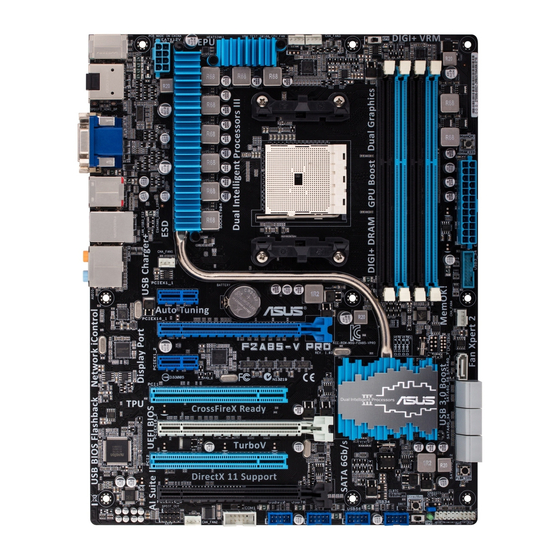
1.3.3 Motherboard layout 23.1cm(9.1in) CHA_FAN2 KBMS_USB34 CPU_FAN GPU_LED DIGI +VRM ATX12V SPDIFO _HDMI MemOK! ESATA6G _USB3 _USB12 AUDIO CHA_FAN1 PCIEX1_1 F2A85-V Atheros 8161 PCIEX16_1 Super Lithium Cell PCIEX1_2 CMOS Power ® A85X PCI1 PCIEX16_2 64Mb BIOS PCI2 Realtek SATA6G_4 SATA6G_5 SATA6G_6 SATA6G_7 ALC887 PCI3 SATA6G_1 SATA6G_2 SATA6G_3... -
Page 19: Layout Contents
Ensure that you use a CPU designed for the FM2 socket. The CPU fits in only one correct orientation. DO NOT force the CPU into the socket to prevent bending the pins and damaging the CPU! F2A85-V F2A85-V CPU socket FM2 ASUS F2A85-V... -
Page 20: Cpu Installation
1.4.1 CPU installation Chapter 1: Product introduction... -
Page 21: Cpu Heatsink And Fan Assembly Installation
1.4.2 CPU heatsink and fan assembly installation Apply the Thermal Interface Material to the CPU heatsink and CPU before you install the heatsink and fan if necessary. To install the CPU heatsink and fan assembly ASUS F2A85-V... - Page 22 To uninstall the CPU heatsink and fan assembly Chapter 1: Product introduction 1-10...
-
Page 23: System Memory
DDR2 DIMM socket. DDR3 modules are developed for better performance with less power consumption. The figure illustrates the location of the DDR3 DIMM sockets: Channel Sockets Channel A DIMM_A1 and DIMM_A2 F2A85-V Channel B DIMM_B1 and DIMM_B2 F2A85-V 240-pin DDR3 DIMM sockets ASUS F2A85-V 1-11... -
Page 24: Memory Configurations
• The maximum 64GB memory capacity can be supported with 16GB or above DIMMs. ASUS will update the memory QVL once the DIMMs are available in the market. • The default memory operation frequency is dependent on its Serial Presence Detect (SPD), which is the standard way of accessing information from a memory module. - Page 25 KHX2000C9AD3W1K2/4GX(XMP) 4GB(2 x 2GB) 1.65V • • Kingston KHX2000C9AD3T1K2/4GX(XMP) 4GB(2 x 2GB) 1.65V • • Kingston KHX2000C9AD3W1K3/6GX(XMP) 6GB(3 x 2GB) 1.65V • • Kingston KHX2000C9AD3T1K3/6GX(XMP) 6GB(3 x 2GB) 1.65V • • HYNIX H5TQ2G83BFR Asint SLA302G08-ML2HB(XMP) • • ASUS F2A85-V 1-13...
- Page 26 DDR3 1866 MHz capability DIMM socket support Chip Chip (Optional) Vendors Part No. Size Timing Voltage Brand 1 DIMM 2 DIMMs 4 DIMMs Corsair CMT4GX3M2A1866C9(XMP) 4GB(2 x 2GB) 9-9-9-24 1.65V • • • Corsair CMT6GX3MA1866C9(XMP) 6GB(3 x 2GB) 9-9-9-24 1.65V •...
- Page 27 G-1201 Silicon S-POWER 20YT5N SP004GBLTU160V02(XMP) • • Power G-1201 Apacer AM5D590 Apacer 78.B1GE3.9L10C • • • KZZC 8DEQSCK Kingston KHX16C9K2/16 16GB(8GB x 2) DS 1.5V • • • N2CB4G8 Elixir M2X8G64CB8HB5N-DG(XMP) Elixir 1213 • • • BOBN-DG ASUS F2A85-V 1-15...
- Page 28 DDR3 1333 MHz capability DIMM socket support Chip (Optional) Vendors Part No. Size Chip NO. Timing Voltage Brand 1 DIMM 2 DIMMs 4 DIMMs AD30908C8D-151C A-DATA AD31333001GOU A-Data • E0906 A-DATA AD3U1333C2G9 A-DATA 3CCD-1509HNA1126L - • • • A-DATA AM2U139C2P1 ADATA 3CCD-1509A EL1127T - •...
- Page 29 • • • POWER Silicon Power SP004GBLTU133V02 S-POWER 20YT3NG-1201 • • TAKEMS TMS2GB364D081-107EY 7-7-7-20 1.5V • TAKEMS TMS2GB364D082-138EW 8-8-8-24 1.5V • • • UMAX E41302GP0-73BDB UMAX U2S24D30TP-13 • • • WINTEC 3WVS31333-2G-CNR AMPO AM3420803-13H • • • ASUS F2A85-V 1-17...
- Page 30 A2 and B2 for better compatibility. • 4 DIMMs: Supports four (4) modules inserted into both the blue and black slots as two pairs of Dual-channel memory configuration. Visit the ASUS website at www.asus.com for the latest QVL. Chapter 1: Product introduction 1-18...
-
Page 31: Installing A Dimm
1.5.3 Installing a DIMM To remove a DIMM ASUS F2A85-V 1-19... -
Page 32: Expansion Slots
Expansion slots In the future, you may need to install expansion cards. The following sub-sections describe the slots and the expansion cards that they support. Unplug the power cord before adding or removing expansion cards. Failure to do so may cause you physical injury and damage motherboard components. -
Page 33: Irq Assignments For This Motherboard
– – – – HD Audio shared – – – – – – PCI_1 – – – – shared – – PCI_2 – – – – – shared – PCI_3 – – – – – – shared ASUS F2A85-V 1-21... -
Page 34: Jumpers
Jumpers Clear RTC RAM (3-pin CLRTC) This jumper allows you to clear the Real Time Clock (RTC) RAM in CMOS. You can clear the CMOS memory of date, time, and system setup parameters by erasing the CMOS RTC RAM data. The onboard button cell battery powers the RAM data in CMOS, which include system setup information such as system passwords. -
Page 35: Connectors
Line Out port (lime). This port connects to a headphone or a speaker. In the 4, 6 and 8-channel configurations, the function of this port becomes Front Speaker Out. Microphone port (pink). This port connects to a microphone. ASUS F2A85-V 1-23... - Page 36 Side Speaker Out port (gray). This port connects to the side speakers in the 8- channel audio configuration. Refer to the audio configuration table below for the function of the audio ports in the 2, 4, 6, or 8-channel configuration. Audio 2, 4, 6, or 8-channel configuration Headset Port...
-
Page 37: Internal Connectors
• The CPU_FAN connector supports a CPU fan of maximum 2A (24 W) fan power. • Only the CPU_FAN and CHA_FAN1/2 connectors support the ASUS Fan Xpert+ feature. • If you install two VGA cards, we recommend that you plug the rear chassis fan cable to the motherboard connector labeled CHA_FAN1/2 for better thermal environment. - Page 38 The system may become unstable or may not boot up if the power is inadequate. • If you are uncertain about the minimum power supply requirement for your system, refer to the Recommended Power Supply Wattage Calculator at http://support.asus. com/PowerSupplyCalculator/PSCalculator.aspx?SLanguage=en-us for details. Chapter 1: Product introduction 1-26...
- Page 39 This connector is for a serial (COM) port. Connect the serial port module cable to this connector, then install the module to a slot opening at the back of the system chassis. PIN 1 F2A85-V F2A85-V Serial port (COM) connector The COM module is purchased separately. ASUS F2A85-V 1-27...
-
Page 40: System Panel Connector (20-8 Pin Panel)
System panel connector (20-8 pin PANEL) This connector supports several chassis-mounted functions. PLED SPEAKER PANEL PIN 1 F2A85-V IDE_LED PWRSW RESET * Requires an ATX power supply F2A85-V System panel connector • System power LED (2-pin PLED) This 2-pin connector is for the system power LED. Connect the chassis power LED cable to this connector. - Page 41 If you want to connect a high definition front panel audio module to this connector, set the Front Panel Type item in the BIOS to [HD]. See section 2.5.5 Onboard Devices Configuration for details. • The front panel audio I/O module is purchased separately. ASUS F2A85-V 1-29...
-
Page 42: Usb 2.0 Connectors
IntA_P1_SSTX- IntA_P2_SSRX+ IntA_P1_SSRX+ IntA_P2_SSRX- IntA_P1_SSRX- Vbus Vbus PIN 1 F2A85-V USB3.0 Front panel connector You can connect the ASUS front panel USB 3.0 bracket to this connector to obtain the front panel USB 3.0 solution. Chapter 1: Product introduction 1-30... -
Page 43: Onboard Switches
BIOS default settings. A message will appear during POST reminding you that the BIOS has been restored to its default settings. • We recommend that you download and update to the latest BIOS version from the ASUS website at www.asus.com after using the MemOK! function. ASUS F2A85-V 1-31... - Page 44 GPU Boost switch This switch allows you to enable or disable the GPU Boost function. F2A85-V F2A85-V GPU Boost switch Chapter 1: Product introduction 1-32...
-
Page 45: Onboard Leds
This user-friendly design provides an intuitional way to locate the root problem within a second. DRAM LED F2A85-V F2A85-V DRAM LED GPU Boost LED The GPU Boost LED lights when the GPU Boost switch is turned to Enable. GPU_LED F2A85-V F2A85-V GPU Boost LED ASUS F2A85-V 1-33... -
Page 46: Software Support
The contents of the Support DVD are subject to change at any time without notice. Visit the ASUS website at www.asus.com for updates. To run the Support DVD Place the Support DVD into the optical drive. -
Page 47: Chapter 2: Bios Information
BIOS in the future. Copy the original motherboard BIOS using the ASUS Update utility. 2.1.1 ASUS Update utility The ASUS Update is a utility that allows you to manage, save, and update the motherboard BIOS in Windows environment. ®... -
Page 48: Asus Ez Flash 2
Follow the onscreen instructions to complete the updating process. 2.1.2 ASUS EZ Flash 2 The ASUS EZ Flash 2 feature allows you to update the BIOS without using an OS-based utility. Before you start using this utility, download the latest BIOS file from the ASUS website at www.asus.com. -
Page 49: Asus Crashfree Bios 3 Utility
2.1.3 ASUS CrashFree BIOS 3 utility The ASUS CrashFree BIOS 3 is an auto recovery tool that allows you to restore the BIOS file when it fails or gets corrupted during the updating process. You can restore a corrupted BIOS file using the motherboard support DVD or a USB flash drive that contains the updated BIOS file. -
Page 50: Asus Bios Updater
2.1.4 ASUS BIOS Updater The ASUS BIOS Updater allows you to update BIOS in DOS environment. This utility also allows you to copy the current BIOS file that you can use as a backup when the BIOS fails or gets corrupted during the updating process. -
Page 51: Updating The Bios File
Updating the BIOS file To update the BIOS file using BIOS Updater At the FreeDOS prompt, type bupdater /pc /g and press <Enter>. D:\>bupdater /pc /g The BIOS Updater screen appears as below. ASUSTek BIOS Updater for DOS V1.30 Current ROM Update ROM BOARD: F2A85-V... -
Page 52: Bios Setup Program
BIOS menu screen The BIOS setup program can be used under two modes: EZ Mode and Advanced Mode. You can change modes from the Exit menu or from the Exit/Advanced Mode button in the EZ Mode/Advanced Mode screen. ASUS F2A85-V... - Page 53 Advanced Mode Power Saving mode Loads optimized default Selects the Advanced mode functions Normal mode ASUS Optimal mode Selects the boot device priority Selects the boot Displays the system properties of the device priority selected mode on the right hand side Displays the Advanced mode menus •...
-
Page 54: Advanced Mode
The Advanced Mode provides advanced options for experienced end-users to configure the BIOS settings. The figure below shows an example of the Advanced Mode. Refer to the following sections for the detailed configurations. To access the EZ Mode, click Exit, then select ASUS EZ Mode. Back button Menu items... -
Page 55: Menu Items
Menu items The highlighted item on the menu bar displays the specific items for that menu. For example, selecting Main shows the Main menu items. The other items (Ai Tweaker, Advanced, Monitor, Boot, Tool, and Exit) on the menu bar have their respective menu items. -
Page 56: Main Menu
RAM to clear the BIOS password. See section 1.7 Jumpers for information on how to erase the RTC RAM. The Administrator or User Password items on top of the screen show the default • Not Installed. After you set a password, these items show Installed. 2-10 ASUS F2A85-V... -
Page 57: Administrator Password
Administrator Password If you have set an administrator password, we recommend that you enter the administrator password for accessing the system. Otherwise, you might be able to see or change only selected fields in the BIOS setup program. To set an administrator password: Select the Administrator Password item and press <Enter>. -
Page 58: Ai Tweaker Menu
CPU Load Line Calibration Auto CPU/NB Load Line Calibration Auto CPU Current Capability 100% CPU/NB Current Capability 100% CPU Power Phase Control Standard CPU Voltage Frequency CPU Power Duty Control T.Probe Version 2.10.1208. Copyright (C) 2012 American Megatrends, Inc. 2-12 ASUS F2A85-V... -
Page 59: Ai Overclock Tuner [Auto]
Target CPU Speed : xxxxMHz Displays the current CPU speed. Target DRAM Speed : xxxxMHz Displays the current DRAM speed. 2.4.1 Ai Overclock Tuner [Auto] Allows you to select the CPU overclocking options to achieve the desired CPU internal frequency. Select any of these preset overclocking configuration options: [Auto] Loads the optimal settings for the system. -
Page 60: Gpu Boost [Auto]
CPU permanently, and setting a low voltage may make the system unstable. VDDNB Offset Mode Sign [+] To offset the voltage by a positive value. [–] To offset the voltage by a negative value. 2-14 ASUS F2A85-V... -
Page 61: Dram Voltage [Auto]
VDDNB Offset Voltage [Auto] Allows you to set the VDDNB Offset voltage. The values range from 0.00625V to 0.36250V with a 0.00625V interval. 2.4.10 DRAM Voltage [Auto] Allows you to set the DRAM voltage. The values range from 1.35V to 2.00V with a 0.01V interval. - Page 62 Reducing phase number under light system loading to increase VRM efficiency. [Standard] Proceeds phase control depending on the CPU loading. [Optimized] Loads the ASUS optimized phase tuning profile. [Extreme] Proceeds the full phase mode. [Manual Adjustment] Allows manual adjustment.
-
Page 63: Advanced Menu
Advanced menu The Advanced menu items allow you to change the settings for the CPU and other system devices. Be cautious when changing the settings of the Advanced menu items. Incorrect field values can cause the system to malfunction. EFI BIOS Utility - Advanced Mode Exit Main Ai Tweaker... -
Page 64: Sata Configuration
Select this option when using legacy operating systems. [UEFI DRIVER] Select this option when using UEFI operating systems. OnChip SATA MAX Speed [SATA 6.0Gb/s] Sets the maximum onboard SATA port speed. Configuration options: [SATA 3.0Gb/s] [SATA 6.0Gb/s] 2-18 ASUS F2A85-V... -
Page 65: Usb Configuration
S.M.A.R.T. Status Check [Enabled] S.M.A.R.T. (Self-Monitoring, Analysis and Reporting Technology) is a monitor system. When read/write of your hard disk errors occur, this feature allows the hard disk to report warning messages during the POST. Configuration options: [Enabled] [Disabled] 2.5.3 USB Configuration The items in this menu allow you to change the USB-related features. -
Page 66: Onboard Devices Configuration
The system goes into on state after an AC power loss. [Power Off] The system goes into off state after an AC power loss. [Last State] The system goes into either off or on state, whatever the system state was before the AC power loss. 2-20 ASUS F2A85-V... -
Page 67: Network Stack
Power On By PS/2 Keyboard [Disabled] [Disabled] Disables the Power On by a PS/2 keyboard. [Space Bar] Sets the Space Bar on the PS/2 keyboard to turn on the system. [Ctrl-Esc] Sets the Ctrl+Esc key on the PS/2 keyboard to turn on the system. [Power Key] Sets Power key on the PS/2 keyboard to turn on the system. -
Page 68: Monitor Menu
Monitor menu The Monitor menu displays the system temperature/power status, and allows you to change the fan settings. Scroll down to display the following items: 2-22 ASUS F2A85-V... -
Page 69: Cpu Temperature / Mb Temperature [Xxxºc/Xxxºf]
2.6.1 CPU Temperature / MB Temperature [xxxºC/xxxºF] The onboard hardware monitor automatically detects and displays the CPU and motherboard temperatures. Select Ignore if you do not wish to display the detected temperatures. 2.6.2 CPU_FAN / CHA_FAN1/2 Speed [xxxx RPM] or [Ignore] / [N/A] The onboard hardware monitor automatically detects and displays the CPU / chassis fan speeds in rotations per minute (RPM). -
Page 70: Cha_Fan1/2 Q-Fan Control [Enabled]
The onboard hardware monitor automatically detects the voltage output through the onboard voltage regulators. Select Ignore if you do not want to detect this item. 2.6.6 Anti Surge Support [Enabled] This item allows you to enable or disable the Anti Surge function. Configuration options: [Disabled] [Enabled] 2-24 ASUS F2A85-V... -
Page 71: Boot Menu
Boot menu The Boot menu items allow you to change the system boot options. Scroll down to display the following items: Chapter 2: BIOS information 2-25... -
Page 72: Fast Boot [Enabled]
[Disabled] Disables the full screen logo display feature. Set this item to [Enabled] to use the ASUS MyLogo 2™ feature. Post Report [5 sec] This item appears only when the Full Screen Logo item is set to [Disabled] and allows you to set the waiting time for the system to display the post report. -
Page 73: Post Delay Time [3 Sec]
2.7.3 Post Delay Time [3 sec] This item appears only when the Full Screen Logo item is set to [Enabled] and allows you to set the POST Report wait time. This configuration only functions in Normal Boot mode. Configuration options: [0 sec] [1 sec] [2 sec] [3 sec] [4 sec] [5 sec] [6 sec] [7 sec] [8 sec] [9 sec] [10 sec] 2.7.4 Bootup NumLock State [On]... -
Page 74: Security Boot
Copy PK to File Configuration options: [Acpi (a0341d0, 0)\PCI (1212)\USB (2, 0)\HD(Part1, Sig ?)\] Delete the PK Configuration options: [Yes] [No] KEK Management Load KEK from File Configuration options: [Acpi (a0341d0, 0)\PCI (1212)\USB (2, 0)\HD(Part1, Sig ?)\] 2-28 ASUS F2A85-V... -
Page 75: Boot Option Priorities
• To select the boot device during system startup, press <F8> when ASUS Logo appears. • To access Windows OS in Safe Mode, press <F8> after POST. -
Page 76: Tools Menu
> ASUS O.C. Profile 2.8.1 ASUS EZ Flash 2 Utility Allows you to run ASUS EZ Flash 2. Press [Enter] to launch the ASUS EZ Flash 2 screen. For more details, see section 2.1.2 ASUS EZ Flash 2. 2.8.2 ASUS SPD Information... -
Page 77: Exit Menu
Load Optimized Defaults Save Changes & Reset Discard Changes & Exit ASUS EZ Mode Launch EFI Shell from filesystem device Load Optimized Defaults This option allows you to load the default values for each of the parameters on the Setup menus. - Page 78 2-32 ASUS F2A85-V...
-
Page 79: Appendices
Cet appareil est conforme aux normes CNR exemptes de licence d’Industrie Canada. Le fonctionnement est soumis aux deux conditions suivantes : (1) cet appareil ne doit pas provoquer d’interférences et (2) cet appareil doit accepter toute interférence, y compris celles susceptibles de provoquer un fonctionnement non souhaité de l’appareil. ASUS F2A85-V... -
Page 80: Canadian Department Of Communications Statement
ASUS Recycling/Takeback Services ASUS recycling and takeback programs come from our commitment to the highest standards for protecting our environment. We believe in providing solutions for you to be able to responsibly recycle our products, batteries, other components as well as the packaging materials. -
Page 81: Asus Contact Information
+1-812-282-3777 +1-510-608-4555 Web site usa.asus.com Technical Support Telephone +1-812-282-2787 Support fax +1-812-284-0883 Online support support.asus.com ASUS COMPUTER GmbH (Germany and Austria) Address Harkort Str. 21-23, D-40880 Ratingen, Germany +49-2102-959911 Web site www.asus.de Online contact www.asus.de/sales Technical Support Telephone +49-1805-010923* Support Fax... - Page 82 Appendices...