Table of Contents
Advertisement
Advertisement
Table of Contents

Related Manuals for Intel BLKDG31PR - 1333FSB DDR2 800 Audio Lan 4SATA uATX 10Pack Motherboard


Summary of Contents for Intel BLKDG31PR - 1333FSB DDR2 800 Audio Lan 4SATA uATX 10Pack Motherboard
- Page 1 Intel® Desktop Board DG31PR Product Guide Order Number: D99182-001...
-
Page 2: Revision History
WARRANTIES RELATING TO FITNESS FOR A PARTICULAR PURPOSE, MERCHANTABILITY, OR INFRINGEMENT OF ANY PATENT, COPYRIGHT OR OTHER INTELLECTUAL PROPERTY RIGHT. Intel products are not intended for use in medical, life saving, or life sustaining applications. Intel may make changes to specifications and product descriptions at any time, without notice. -
Page 3: Intended Audience
The suitability of this product for other PC or embedded non-PC applications or other environments, such as medical, industrial, alarm systems, test equipment, etc. may not be supported without further evaluation by Intel. Document Organization The chapters in this Product Guide are arranged as follows:... -
Page 4: Box Contents
Intel Desktop Board DG31PR Product Guide Conventions The following conventions are used in this manual: CAUTION Cautions warn the user about how to prevent damage to hardware or loss of data. NOTE Notes call attention to important information. Terminology The table below gives descriptions of some common terms used in the product guide. -
Page 5: Table Of Contents
G31 Express Chipset .................14 ® Intel G33 Graphics Subsystem..............15 ® ® Intel GMA 3100 Graphics Controller (Intel GMA 3100) ......15 Audio Subsystem ....................16 Legacy Input/Output (I/O) Controller ..............17 LAN Subsystem ....................17 RJ-45 LAN Connector LEDs................17 Hi-Speed USB 2.0 Support ..................18 Enhanced IDE Interface ..................18... - Page 6 Intel Desktop Board DG31PR Product Guide Installing and Removing a Processor ..............31 Installing a Processor ..................31 Installing the Processor Fan Heat Sink ............34 Connecting the Processor Fan Heat Sink Cable..........35 Removing the Processor ................36 Installing and Removing Memory................36 Installing DIMMs ..................37 Removing DIMMs..................39...
- Page 7 1. Feature Summary..................9 2. Desktop Board DG31PR Components ...............12 3. LAN Connector LEDs ..................18 4. Front Panel Intel High Definition Audio Header Signal Names ......46 5. S/PDIF Connector ..................46 6. Chassis Intrusion Header ................46 7. Serial Port Header Signal Names..............47 8.
- Page 8 Intel Desktop Board DG31PR Product Guide viii...
-
Page 9: Desktop Board Features
• 800/667 MHz single or dual channel DDR2 SDRAM interface • Support for up to 4 GB of system memory ® Chipset Intel G31 Express Chipset consisting of: • Intel G31 Express Chipset Graphics and Memory Controller Hub ® ® (GMCH) with Intel Graphics Media Accelerator 3100 (Intel 3100) ®... -
Page 10: Supported Operating Systems
Intel Desktop Board DG31PR Product Guide Table 1. Feature Summary (continued) ® BIOS • Intel Platform Innovation Framework for extensible firmware interface • 4 Mbit symmetrical flash memory device • Support for SMBIOS ® • Intel Rapid BIOS Boot ®... -
Page 11: Desktop Board Components
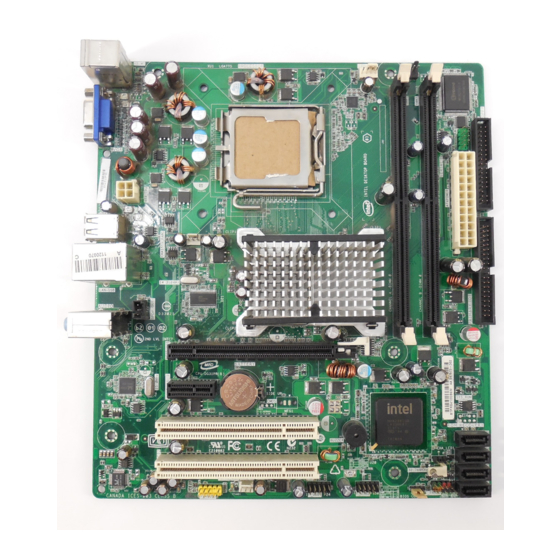
Desktop Board Features Desktop Board Components Figure 1 shows the approximate location of the major components on Desktop Board DG31PR. Figure 1. Desktop Board DG31PR Components... -
Page 12: Desktop Board Dg31Pr Components
Intel Desktop Board DG31PR Product Guide Table 2. Desktop Board DG31PR Components Label Description PCI bus connector 2 PCI bus connector 1 Battery PCI Express x1 connector PCI Express x16 connector S/PDIF connector Back panel connectors 12 V processor core voltage connector (2 x 2 pin) -
Page 13: Processor
Desktop Board may result in damage to the board, or the system may not function properly. Desktop Board DG31PR supports an Intel processor in the LGA775 package. Processors are not included with the Desktop Board and must be purchased separately. -
Page 14: Intel G31 Express Chipset
DMI interconnect. The component also provides integrated graphics capabilities supporting 3D, 2D, and display capabilities. The ICH7 is a centralized controller for the board’s I/O paths. Related Links: Go to the following link for more information about the Intel G31 Express Chipset: http://developer.intel.com/design/nav/pcserver.htm... -
Page 15: Intel G33 Graphics Subsystem
⎯ DDC2B compliant interface with Advanced Digital Display 2 card or Media Expansion Card (ADD2/MEC), support for TV-out/TV-in and DVI digital display connections NOTE A minimum of 512 MB of system memory is required in order for the Intel GMA 3100 integrated graphics controller to operate properly. -
Page 16: Audio Subsystem
A signal-to-noise (S/N) ratio of 95 dB • Independent multi-streaming 5.1 audio (using the back panel audio connectors) and stereo (using the Intel High Definition front panel audio header) Related Links: Go to the following link or pages for more information about: •... -
Page 17: Legacy Input/Output (I/O) Controller
Intelligent power management, including a programmable wake up event interface • PCI power management support LAN Subsystem The LAN subsystem includes: • Intel ICH7 • Realtek 8111-GR Gigabit Ethernet Controller for operation at 10/100/1000 Mb/s • RJ-45 LAN connector with integrated status LEDs The subsystem features: •... -
Page 18: Hi-Speed Usb 2.0 Support
Intel Desktop Board DG31PR Product Guide Table 3 describes the LED states when the board is powered up and the LAN subsystem is operating. Table 3. LAN Connector LEDs LED Color LED State Indicates Green LAN link is not established... -
Page 19: Expandability
Desktop Board Features Expandability For system expansion, the Desktop Board provides the following expansion slots: • One PCI Express x1 connector • One PCI Express x16 connector • Two PCI bus connectors BIOS The BIOS provides the Power-On Self-Test (POST), the BIOS Setup program, the PCI/PCI Express and IDE auto-configuration utilities, and the video BIOS. -
Page 20: Security Passwords
Intel Desktop Board DG31PR Product Guide Security Passwords The BIOS includes security features that restrict whether the BIOS Setup program can be accessed and who can boot the computer. A supervisor password and a user password can be set for the BIOS Setup and for booting the computer, with the following restrictions: •... -
Page 21: Hardware Monitoring And Fan Speed Control
Desktop Board Features Hardware Monitoring and Fan Speed Control The features of the hardware monitoring and fan speed control include: • Monitoring of power supply voltages to detect levels above and below acceptable values • Fan speed controllers and sensors integrated into the legacy I/O controller •... -
Page 22: Hardware Support
Intel Desktop Board DG31PR Product Guide Hardware Support Power Connectors ATX12V-compliant power supplies can turn off the computer power through system control. When an ACPI-enabled computer receives the correct command, the power supply removes all non-standby voltages. When resuming from an AC power failure, the computer returns to the power state it was in before power was interrupted (either on or off). -
Page 23: Instantly Available Pc Technology
Desktop Board Features Instantly Available PC Technology CAUTIONS For Instantly Available PC technology, the 5 V standby line for the power supply must be capable of delivering adequate +5 V standby current. Failure to provide adequate standby current when using this feature can damage the power supply and/or effect ACPI S3 sleep state functionality. -
Page 24: Wake From Usb
Intel Desktop Board DG31PR Product Guide Figure 3. Location of the Standby Power Indicator Related Links: For more information on standby current requirements for the Desktop Board, refer to the Technical Product Specification by going to the following link, finding the product, and selecting Product Documentation from the left-hand menu: http://support.intel.com/support/motherboards/desktop/... -
Page 25: Pme# Signal Wake-Up Support
ENERGY STAR* Capable In 2007, the US Department of Energy and the US Environmental Protection Agency revised the ENERGY STAR requirements. Intel worked directly with these two governmental agencies to define the new requirements. Currently Intel Desktop Boards are capable of meeting the new ENERGY STAR requirements depending upon system configuration. - Page 26 Intel Desktop Board DG31PR Product Guide...
-
Page 27: Installing And Replacing Desktop Board Components
2 Installing and Replacing Desktop Board Components This chapter tells you how to: • Install the I/O shield • Install and remove the Desktop Board • Install and remove a processor • Install and remove memory • Install and remove a PCI Express x16 card •... -
Page 28: Installation Precautions
Intel Desktop Board DG31PR Product Guide Installation Precautions When you install and test the Intel Desktop Board, observe all warnings and cautions in the installation instructions. To avoid injury, be careful of: • Sharp pins on connectors • Sharp pins on printed circuit assemblies •... -
Page 29: Installing The I/O Shield
Installing and Replacing Desktop Board Components Installing the I/O Shield The Desktop Board comes with an I/O shield. When installed in the chassis, the shield blocks radio frequency transmissions, protects internal components from dust and foreign objects, and promotes correct airflow within the chassis. Install the I/O shield before installing the Desktop Board in the chassis. -
Page 30: Installing And Removing The Desktop Board
Intel Desktop Board DG31PR Product Guide Installing and Removing the Desktop Board CAUTION Only qualified technical personnel should do this procedure. Disconnect the computer from its power source before performing the procedures described here. Failure to disconnect the power before you open the computer can result in personal injury or equipment damage. -
Page 31: Installing And Removing A Processor
Installing and Replacing Desktop Board Components Installing and Removing a Processor Instructions on how to install the processor to the Desktop Board are given below. Installing a Processor CAUTION Before installing or removing the processor, make sure the AC power has been removed by unplugging the power cord from the computer;... -
Page 32: Lift The Load Plate
Intel Desktop Board DG31PR Product Guide 3. Lift the load plate (Figure 7, A). Do not touch the socket contacts (Figure 7, B). Figure 7. Lift the Load Plate 4. Remove the plastic protective socket cover from the load plate (Figure 8). Do not discard the protective socket cover. -
Page 33: Remove The Processor From The Protective Processor Cover
Installing and Replacing Desktop Board Components 5. Remove the processor from the protective processor cover. Hold the processor only at the edges, being careful not to touch the bottom of the processor (see Figure 9). Do not discard the protective processor cover. Always replace the processor cover if the processor is removed from the socket. -
Page 34: Installing The Processor Fan Heat Sink
Intel Desktop Board DG31PR Product Guide 7. Pressing down on the load plate (Figure 11, A), close and engage the socket lever (Figure 11, B). Figure 11. Close the Load Plate Installing the Processor Fan Heat Sink Desktop Board DG31PR has mounting holes for a processor fan heat sink. For instructions on how to attach the processor fan heat sink to the Desktop Board, refer to the boxed processor manual. -
Page 35: Connecting The Processor Fan Heat Sink Cable
Installing and Replacing Desktop Board Components Connecting the Processor Fan Heat Sink Cable Connect the processor fan heat sink cable to the 4-pin processor fan header (see Figure 12). A fan with a 4-pin connector as shown in Figure 12, A is recommended; however, a fan with a 3-pin connector (Figure 12, B) can be used. -
Page 36: Removing The Processor
Installing and Removing Memory NOTE To be fully compliant with all applicable Intel SDRAM memory specifications, the board requires DIMMs that support the Serial Presence Detect (SPD) data structure. The desktop board has two 240-pin DDR2 DIMM sockets providing Channel A and Channel B. -
Page 37: Installing Dimms
Installing and Replacing Desktop Board Components Installing DIMMs To make sure you have the correct DIMM, place it on the illustration of the DDR2 DIMM in Figure 14. All the notches should match with the DDR2 DIMM. Figure 14. Use DDR2 DIMMs... -
Page 38: Installing A Dimm
Intel Desktop Board DG31PR Product Guide NOTE Memory must be installed in the Channel A, DIMM 0 socket to enable Intel Quiet ® System Technology. To install a DIMM, follow these steps: 1. Observe the precautions in "Before You Begin" on page 27. -
Page 39: Removing Dimms
Installing and Replacing Desktop Board Components 7. Insert the bottom edge of the DIMM into the socket. 8. When the DIMM is inserted, push down on the top edge of the DIMM until the retaining clips snap into place. Make sure the clips are firmly in place. 9. -
Page 40: Installing A Pci Express X16 Card
Intel Desktop Board DG31PR Product Guide Installing a PCI Express x16 Card CAUTION When installing a PCI Express x16 card on the desktop board, ensure that the card is fully seated in the PCI Express x16 connector before you power on the system. If the card is not fully seated in the PCI Express connector, an electrical short may result across the PCI Express connector pins. -
Page 41: Removing The Pci Express X16 Card
Installing and Replacing Desktop Board Components Removing the PCI Express x16 Card Follow these instructions to remove the PCI Express x16 card from the connector: 1. Observe the precautions in "Before You Begin" on page 27. 2. Remove the screw (Figure 17, A) that secures the card’s metal bracket to the chassis back panel. -
Page 42: Connecting The Diskette Drive Cable
For correct function of the cable: 1. Observe the precautions in "Before You Begin" on page 27. 2. Attach the cable end labeled P1 to the diskette drive connector on the Intel Desktop Board (Figure 18, A). 3. Attach the cable end labeled P2 to the diskette drive (Figure 18, B). -
Page 43: Connecting The Ide Cable
For correct function of the cable: 1. Observe the precautions in "Before You Begin" on page 27. 2. Attach the cable end with the single connector (blue) to the Intel Desktop Board (Figure 19, A). 3. Attach the cable end with the two closely spaced connectors (gray and black) to the drives (Figure 19, B). -
Page 44: Connecting The Serial Ata (Sata) Cables
Intel Desktop Board DG31PR Product Guide Connecting the Serial ATA (SATA) Cables SATA cables support the Serial ATA protocol. Each cable can be used to connect a single internal SATA drive to the Desktop Board. For correct cable function: 1. Observe the precautions in “Before You Begin” on page 27. -
Page 45: Connecting To The Internal Headers And Connectors
Installing and Replacing Desktop Board Components Connecting to the Internal Headers and Connectors Before connecting cables to the internal headers and connectors, observe the precautions in “Before You Begin” on page 27. Figure 21 shows the location of the internal headers and connectors for Desktop Board DG31PR. Item Description Front Panel Audio... -
Page 46: Connecting To The Front Panel Audio Header
Figure 21, A on page 45 shows the location of the front panel audio header. Table 4 shows the pin assignments for the front panel audio header. Table 4. Front Panel Intel High Definition Audio Header Signal Names Signal Name... -
Page 47: Connecting To The Serial Port Header
Installing and Replacing Desktop Board Components Connecting to the Serial Port Header See Figure 21, D on page 45 for the location of the serial port header. Table 7 shows the pin assignments for the serial port header. Table 7. Serial Port Header Signal Names Signal Name Signal Name RXD#... -
Page 48: Connecting To The Front Panel Header
Intel Desktop Board DG31PR Product Guide Connecting to the Front Panel Header Before connecting to the front panel header, observe the precautions in "Before You Begin" on page 27. See Figure 21, F on page 45 for the location of the multi-colored front panel header. -
Page 49: Connecting To The Audio System
Installing and Replacing Desktop Board Components Connecting to the Audio System After installing the audio driver from the Intel Express Installer CD-ROM, the multi- channel audio feature can be enabled. Figure 22 shows the back panel audio connectors. The default connector assignments are shown in the table. -
Page 50: Connecting Chassis Fan And Power Supply Cables
Intel Desktop Board DG31PR Product Guide Connecting Chassis Fan and Power Supply Cables Connecting Chassis Fan Cables Connect chassis fan cables to the 3-pin chassis fan headers on the Desktop Board. Figure 23 shows the location of the chassis fan headers. -
Page 51: Connecting Supply Power Cables
Installing and Replacing Desktop Board Components Connecting Supply Power Cables CAUTION Failure to use an appropriate power supply and/or not connecting the 12 V (2 x 2 pin) power connector to the Desktop Board may result in damage to the board or the system may not function properly. -
Page 52: Setting The Bios Configuration Jumper
Intel Desktop Board DG31PR Product Guide Setting the BIOS Configuration Jumper NOTE Always turn off the power and unplug the power cord from the computer before moving the jumper. Moving the jumper with the power on may result in unreliable computer operation. -
Page 53: Clearing Passwords
Installing and Replacing Desktop Board Components Clearing Passwords This procedure assumes that the board is installed in the computer and the configuration jumper block is set to normal mode. 1. Observe the precautions in "Before You Begin" on page 27. 2. -
Page 54: Replacing The Battery
Intel Desktop Board DG31PR Product Guide Replacing the Battery A coin-cell battery (CR2032) powers the real-time clock and CMOS memory. When the computer is not plugged into a wall socket, the battery has an estimated life of three years. When the computer is plugged in, the standby current from the power supply extends the life of the battery. - Page 55 Installing and Replacing Desktop Board Components VORSICHT Bei falschem Einsetzen einer neuen Batterie besteht Explosionsgefahr. Die Batterie darf nur durch denselben oder einen entsprechenden, vom Hersteller empfohlenen Batterietyp ersetzt werden. Entsorgen Sie verbrauchte Batterien den Anweisungen des Herstellers entsprechend. AVVERTIMENTO Esiste il pericolo di un esplosione se la pila non viene sostituita in modo corretto.
- Page 56 Intel Desktop Board DG31PR Product Guide VIGYÁZAT Ha a telepet nem a megfelelő típusú telepre cseréli, az felrobbanhat. A telepeket lehetőség szerint újra kell hasznosítani. A használt telepeket a helyi környezetvédelmi előírásoknak megfelelően kell kiselejtezni. AWAS Risiko letupan wujud jika bateri digantikan dengan jenis yang tidak betul. Bateri sepatutnya dikitar semula jika boleh.
- Page 57 Installing and Replacing Desktop Board Components UYARI Yanlış türde pil takıldığında patlama riski vardır. Piller mümkün olduğunda geri dönüştürülmelidir. Kullanılmış piller, yerel çevre yasalarına uygun olarak atılmalıdır. OСТОРОГА Використовуйте батареї правильного типу, інакше існуватиме ризик вибуху. Якщо можливо, використані батареї слід утилізувати. Утилізація використаних батарей...
-
Page 58: Removing The Battery
Intel Desktop Board DG31PR Product Guide To replace the battery, follow these steps: 1. Observe the precautions in "Before You Begin" (see page 27). 2. Turn off all peripheral devices connected to the computer. Disconnect the computer’s power cord from the AC power source (wall outlet or power adapter). -
Page 59: Updating The Bios
Power-On Self-Test (POST) memory test begins and before the operating system boot begins. This chapter tells you how to update the BIOS by either using the Intel Express BIOS Update utility or the Iflash Memory Update utility, and how to recover the BIOS if an update fails. -
Page 60: Updating The Bios With The Iso Image Bios Update File Or The Iflash Memory Update Utility
Intel Flash Memory Update Utility You can obtain either of these files through your computer supplier or by navigating to the Desktop Board DG31PR page on the Intel World Wide Web site at: http://support.intel.com/support/motherboards/desktop Navigate to the DG31PR page, click “[view] Latest BIOS updates,” and select the ISO Image BIOS Update or Iflash BIOS Update utility file. -
Page 61: Updating The Bios With The Iflash Memory Update Utility
CD-ROM, bootable USB flash drive, or other bootable USB media. The utility available on the Intel World Wide Web site provides a simple method for creating a bootable CD-ROM that will automatically update your BIOS. The Iflash BIOS update files can also be extracted locally to your hard drive and copied to a bootable USB flash drive or other bootable USB media. -
Page 62: Recovering The Bios
BIOS could be damaged. Due to BIOS size and recovery requirements, a CD-R with the .BIO file in the root directory will be required. Related Links: For more information about updating the Intel Desktop Board BIOS or recovering from a BIOS update failure, go to: http://support.intel.com/support/motherboards/desktop/sb/CS-022312.htm... -
Page 63: A Error Messages And Indicators
A Error Messages and Indicators Desktop Board DG31PR reports POST errors in two ways: • By sounding a beep code • By displaying an error message on the monitor BIOS Beep Codes The BIOS also issues a beep code (one long tone followed by two short tones) during POST if the video configuration fails (a faulty video card or no card installed) or if an external ROM module does not properly checksum to zero. - Page 64 Intel Desktop Board DG31PR Product Guide...
-
Page 65: B Regulatory Compliance
B Regulatory Compliance This appendix contains the following regulatory compliance information for Desktop Board DG31PR: • Safety standards • European Union Declaration of Conformity statement • Product Ecology statements • Electromagnetic Compatibility (EMC) regulations • Product certifications Safety Standards Desktop Board DG31PR complies with the safety standards stated in Table 14 when correctly installed in a compatible host system. -
Page 66: European Union Declaration Of Conformity Statement
Intel Desktop Board DG31PR Product Guide European Union Declaration of Conformity Statement We, Intel Corporation, declare under our sole responsibility that the product Intel ® Desktop Board DG31PR is in conformity with all applicable essential requirements necessary for CE marking, following the provisions of the European Council Directives 2004/108/EC (EMC Directive) and 2006/95/EC (Low Voltage Directive). -
Page 67: Product Ecology Statements
The following information is provided to address worldwide product ecology concerns and regulations. Recycling Considerations As part of its commitment to environmental responsibility, Intel has implemented the Intel Product Recycling Program to allow retail consumers of Intel’s branded products ®... - Page 68 Français Dans le cadre de son engagement pour la protection de l'environnement, Intel a mis en œuvre le programme Intel Product Recycling Program (Programme de recyclage des produits Intel) pour permettre aux consommateurs de produits Intel de recycler les produits usés en les retournant à...
-
Page 69: Lead-Free Desktop Board
Regulatory Compliance Portuguese Como parte deste compromisso com o respeito ao ambiente, a Intel implementou o Programa de Reciclagem de Produtos para que os consumidores finais possam enviar produtos Intel usados para locais selecionados, onde esses produtos são reciclados de maneira adequada. -
Page 70: Lead-Free Board Markings
Intel Desktop Board DG31PR Product Guide Table 15 shows the lead-free board markings as they appear on the board and accompanying collateral. Table 15. Lead-Free Board Markings Description Mark Lead-Free 2 Level Interconnect: This symbol is used to identify electrical... -
Page 71: Emc Regulations
Regulatory Compliance EMC Regulations Desktop Board DG31PR complies with the EMC regulations stated in Table 16 when correctly installed in a compatible host system. Table 16. EMC Regulations Regulation Title FCC 47 CFR Part 15, Title 47 of the Code of Federal Regulations, Part 15, Subpart B, Subpart B Radio Frequency Devices. -
Page 72: Ensure Electromagnetic Compatibility (Emc) Compliance
Intel Desktop Board DG31PR Product Guide Korean Class B statement translation: This is household equipment that is certified to comply with EMC requirements. You may use this equipment in residential environments and other non-residential environments. Ensure Electromagnetic Compatibility (EMC) Compliance... -
Page 73: Product Certifications
Description Mark UL joint US/Canada Recognized Component mark. Includes adjacent UL file number for Intel Desktop Boards: E210882. FCC Declaration of Conformity logo mark for Class B equipment. Includes Intel name and DG31PR model designation. CE mark. Declaring compliance to European Union (EU) EMC directive and Low Voltage directive. -
Page 74: Chassis And Component Certifications
Intel Desktop Board DG31PR Product Guide Chassis and Component Certifications Ensure that the chassis and certain components; such as the power supply, peripheral drives, wiring, and cables; are components certified for the country or market where used. Agency certification marks on the product are proof of certification. Typical...