ASROCK 880GM-LE FX User Manual
User manual
Hide thumbs
Also See for 880GM-LE FX:
- Installation manual (211 pages) ,
- Quick installation manual (177 pages) ,
- Specifications (6 pages)

Related Manuals for ASROCK 880GM-LE FX


Summary of Contents for ASROCK 880GM-LE FX
-
Page 1: User Manual
880GM-LE FX User Manual Version 1.0 Published October 2011 Copyright©2011 ASRock INC. All rights reserved. 1 1 1 1 1... - Page 2 (including damages for loss of profits, loss of business, loss of data, interruption of business and the like), even if ASRock has been advised of the possibility of such damages arising from any defect or error in the manual or product.
-
Page 3: Table Of Contents
Contents Contents Contents Contents Contents 1 . 1 . 1 . 1 . 1 . Introduction Introduction Introduction ............Introduction ....................................5 5 5 5 5 Introduction ............Package Contents ..............5 Specifications ................6 Motherboard Layout ..............12 I/O Panel .................. - Page 4 3 . 3 . 3 . 3 . BIOS S BIOS S BIOS S BIOS SETUP UTILITY ETUP UTILITY ETUP UTILITY ETUP UTILITY ........................................38 BIOS S ETUP UTILITY ..........Introduction ................38 3.1.1 BIOS Menu Bar ............... 38 3.1.2 Navigation Keys ..............
-
Page 5: Package Contents
In case any modifications of this manual occur, the updated version will be available on ASRock website without further notice. You may find the latest VGA cards and CPU support lists on ASRock website as well. ASRock website http://www.asrock.com If you require technical support related to this motherboard, please visit our website for specific information about the model you are using. -
Page 6: Specifications
Specifications Specifications Specifications Specifications Specifications Platform - Micro ATX Form Factor: 9.6-in x 7.8-in, 24.4 cm x 19.8 cm - Solid Capacitor for CPU power - Support for Socket AM3+ processors - Support for Socket AM3 processors: AMD Phenom II X6 / X4 / X3 / X2 (except 920 / 940) / Athlon II X4 / X3 / X2 / Sempron processors - Supports 8-Core CPU... - Page 7 Support CD OverDrive Utility, AMD Live! Explorer, AMD Fusion, CyberLink MediaEspresso 6.5 Trial, ASRock Software Suite (CyberLink DVD Suite - OEM and Trial; ASRock MAGIX Multimedia Suite - OEM) - ASRock OC Tuner (see CAUTION 7) Unique Feature - ASRock Intelligent Energy Saver (see CAUTION 8)
- Page 8 Certifications - ErP/EuP Ready (ErP/EuP ready power supply is required) (see CAUTION 17) * For detailed product information, please visit our website: http://www.asrock.com WARNING Please realize that there is a certain risk involved with overclocking, including adjusting the setting in the BIOS, applying Untied Overclocking Technology, or using the third- party overclocking tools.
- Page 9 SATAII mode. You can also connect SATA hard disk to SATAII connector directly. It is a user-friendly ASRock overclocking tool which allows you to surveil your system by hardware monitor function and overclock your hardware devices to get the best system performance under Windows ®...
- Page 10 - ASRock APP Charger. Simply installing the APP Charger driver, it makes your iPhone charged much quickly from your computer and up to 40% faster than before. ASRock APP Charger allows you to quickly charge many Apple devices simultaneously and even supports continuous charging when your PC enters into Standby mode (S1), Suspend to RAM (S3), hibernation mode (S4) or power off (S5).
- Page 11 17. EuP, stands for Energy Using Product, was a provision regulated by Euro- pean Union to define the power consumption for the completed system. According to EuP, the total AC power of the completed system shall be under 1.00W in off mode condition. To meet EuP standard, an EuP ready motherboard and an EuP ready power supply are required.
-
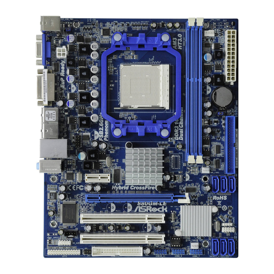
Page 12: Motherboard Layout
B: USB1 880G Chipset PWR_FAN1 PCIE1 Hybrid CrossFire AUDIO SATAII_4 SATAII_5 SATAII_6 CODEC PORT 3) (PORT 4) (PORT 5) PCIE2 RoHS 880GM-LE FX PCI1 SB710 SPEAKER1 PLED PWRBTN Chipset PANEL 1 HDLED RESET PCI2 CHA_FAN1 HD_AUDIO1 BIOS LPT1 USB10_11 USB8_9... -
Page 13: I/O Panel
I/O Panel I/O Panel I/O Panel I/O Panel I/O Panel PS/2 Mouse Port (Green) Microphone (Pink) D-Sub Port USB 2.0 Ports (USB01) DVI-D Port USB 2.0 Ports (USB45) RJ-45 Port USB 2.0 Ports (USB23) Line In (Light Blue) PS/2 Keyboard Port (Purple) Front Speaker (Lime) * There are two LED next to the LAN port. -
Page 14: Installation Installation
2. 2. 2. 2. 2. Installation Installation Installation Installation Installation This is a Micro ATX form factor (9.6-in x 7.8-in, 24.4 cm x 19.8 cm) motherboard. Before you install the motherboard, study the configuration of your chassis to en- sure that the motherboard fits into it. Pre-installation Precautions Pre-installation Precautions Pre-installation Precautions... -
Page 15: Cpu Installation
CPU Installation CPU Installation CPU Installation CPU Installation CPU Installation Step 1. Unlock the socket by lifting the lever up to a 90 angle. Step 2. Position the CPU directly above the socket such that the CPU corner with the golden triangle matches the socket corner with a small triangle. Step 3. -
Page 16: Installation Of Memory Modules (Dimm)
2.3 Installation of Memory Modules (DIMM) 2.3 Installation of Memory Modules (DIMM) 880GM-LE FX motherboard provides two 240-pin DDR3 (Double Data Rate 3) DIMM slots, and supports Dual Channel Memory Technology. For dual channel configuration, you always need to install two identical (the same brand, speed, size and chip-type) memory modules in the DDR3 DIMM slots to activate Dual Channel Memory Technology. -
Page 17: Expansion Slots (Pci And Pci Express Slots)
2.4 Expansion Slots (PCI and PCI Express Slots) 2.4 Expansion Slots (PCI and PCI Express Slots) 2.4 Expansion Slots (PCI and PCI Express Slots) 2.4 Expansion Slots (PCI and PCI Express Slots) 2.4 Expansion Slots (PCI and PCI Express Slots) There are 2 PCI slots and 2 PCI Express slots on this motherboard. -
Page 18: Dual Monitor And Surround Display Features
2.5 Dual Monitor and Surround Display Features 2.5 Dual Monitor and Surround Display Features 2.5 Dual Monitor and Surround Display Features 2.5 Dual Monitor and Surround Display Features 2.5 Dual Monitor and Surround Display Features Dual Monitor Feature This motherboard supports dual monitor feature. With the internal dual VGA output support (DVI-D and D-Sub), you can easily enjoy the benefits of dual monitor feature without installing any add-on VGA card to this motherboard. - Page 19 3. Boot your system. Press <F2> or <Del> to enter BIOS setup. Enter “Share Memory” option to adjust the memory capability to [32MB], [64MB], [128MB] [256MB] or [512MB] to enable the function of D-sub. Please make sure that the value you select is less than the total capability of the system memory. If you do not adjust the BIOS setup, the default value of “Share Memory”, [Auto], will disable D-Sub function when the add-on VGA card is inserted to this motherboard.
- Page 20 HDCP Function HDCP function is supported on this motherboard. To use HDCP function with this motherboard, you need to adopt the monitor that supports HDCP function as well. Therefore, you can enjoy the superior display quality with high-definition HDCP encryption contents. Please refer to below instruction for more details about HDCP function.
-
Page 21: Ati Tm
A A A A A TI TI TI TI TI Hybrid CrossF Hybrid CrossF Hybrid CrossFireX ireX ireX ireX Operation Guide Operation Guide Operation Guide Hybrid CrossF Hybrid CrossF ireX Operation Guide Operation Guide This motherboard supports ATI Hybrid CrossFireX feature. - Page 22 Step 7. Double-click “ATI Catalyst Control Center”. Click “View”, click “CrossFire ”, and then select the option “Enable CrossFire ”. View Enable CrossFire CrossFire Step 8. Click “Yes” to continue. Step 9. Click “OK” to save your change. Step 10. Reboot your system. Then you can freely enjoy the benefit of Hybrid CrossFireX feature.
-
Page 23: Jumpers Setup
2 . 7 2 . 7 2 . 7 Jumpers Setup Jumpers Setup Jumpers Setup 2 . 7 2 . 7 Jumpers Setup Jumpers Setup The illustration shows how jumpers are setup. When the jumper cap is placed on pins, the jumper is “Short”. -
Page 24: Onboard Headers And Connectors
2.8 Onboard Headers and Connectors 2.8 Onboard Headers and Connectors 2.8 Onboard Headers and Connectors 2.8 Onboard Headers and Connectors 2.8 Onboard Headers and Connectors Onboard headers and connectors are NOT jumpers. Do NOT place jumper caps over these headers and connectors. Placing jumper caps over the headers and connectors will cause permanent damage of the motherboard! •... - Page 25 USB 2.0 Headers Besides six default USB 2.0 USB_PWR P-11 ports on the I/O panel, there are (9-pin USB10_11) P+11 DUMMY three USB 2.0 headers on this (see p.12 No. 24) motherboard. Each USB 2.0 header can support two USB P+10 P-10 USB_PWR...
- Page 26 Front Panel Audio Header This is an interface for the front PRESENCE# panel audio cable that allows MIC_RET (9-pin HD_AUDIO1) OUT_RET convenient connection and (see p.12, No. 28) control of audio devices. OUT2_L J_SENSE OUT2_R MIC2_R MIC2_L 1. High Definition Audio supports Jack Sensing, but the panel wire on the chassis must support HDA to function correctly.
- Page 27 Chassis Speaker Header Please connect the chassis speaker to this header. (4-pin SPEAKER 1) SPEAKER DUMMY (see p.12 No. 15) DUMMY Chassis and Power Fan Connectors Please connect the fan cables to the fan connectors and (3-pin CHA_FAN1) +12V CHA_FAN_SPEED match the black wire to the (see p.12 No.
-
Page 28: Sataii Hard Disk Setup Guide
Serial port Header This COM1 header supports a RRXD1 DDTR#1 serial port module. DDSR#1 (9-pin COM1) CCTS#1 (see p.12 No. 34) RRI#1 RRTS#1 TTXD1 DDCD#1 SAT T T T T AII Hard Disk Setup Guide AII Hard Disk Setup Guide AII Hard Disk Setup Guide AII Hard Disk Setup Guide AII Hard Disk Setup Guide... -
Page 29: Installation
2.10 2.10 2.10 Serial A Serial A Serial AT T T T T A (SA Serial A A (SA A (SAT T T T T A) / Serial A A (SA A) / Serial A A) / Serial A A) / Serial AT T T T T AII (SA AII (SA AII (SA AII (SAT T T T T AII) Hard Disks... -
Page 30: Hot Plug And Hot Swap Functions For Sata / Sataii Hdds
2.11 Hot Plug and Hot Swap F 2.11 Hot Plug and Hot Swap Functions for SA 2.11 Hot Plug and Hot Swap F unctions for SA unctions for SAT T T T T A / SA unctions for SA A / SA A / SA A / SAT T T T T AII 2.11 Hot Plug and Hot Swap F... -
Page 31: Sata / Sataii Hdd Hot Plug Feature And Operation Guide
SATA / SATAII Hot Plug support information of our motherboard is indicated in the product spec on our website: www.asrock.com 2. Make sure your SATA / SATAII HDD can support Hot Plug function from your dealer or HDD user manual. - Page 32 How to Hot Plug a SATA / SATAII HDD: Points of attention, before you process the Hot Plug: Please do follow below instruction sequence to process the Hot Plug, improper procedure will cause the SATA / SATAII HDD damage and data loss. Step 1 Step 2 Connect SATA data cable to...
-
Page 33: Driver Installation Guide
Set the “SATA Operation Mode” option to [RAID]. STEP 2: Make a SATA / SATAII Driver Diskette. Insert the ASRock Support CD into your optical drive to boot your system. During POST at the beginning of system boot-up, press <F11> key, and then a window for boot devices selection appears. -
Page 34: Installing Windows ® 7 / 7 64-Bit / Vista
STEP 3: Use “RAID Installation Guide” to set RAID configuration. Before you start to configure RAID function, you need to check the RAID installation guide in the Support CD for proper configuration. Please refer to the BIOS RAID installation guide part of the document in the following path in the Support CD: .. -
Page 35: Tm Tm
NOTE1. If you install Windows 7 / 7 64-bit / Vista / Vista 64-bit on IDE HDDs and want ® to manage (create, convert, delete, or rebuild) RAID functions on SATA / SATAII HDDs, you still need to set up “SATA Operation Mode” to [RAID] in BIOS first. Then, please set the RAID configuration by using the Windows RAID installation guide in the following path in the Support CD: .. -
Page 36: Tm / Vista Tm 64-Bit
Using SATA / SATAII HDDs without NCQ and Hot Plug functions (IDE mode) STEP 1: Set up BIOS. Enter BIOS SETUP UTILITY Advanced screen Storage Configuration. Set the “SATA Operation Mode” option to [IDE]. STEP 2: Install Windows ® XP / XP 64-bit OS on your system. 2.15.2 Installing Windows 2.15.2 Installing Windows 7 / 7 64-bit / Vista... -
Page 37: Untied Overclocking Technology
2.16 2.16 2.16 Untied Overclocking T Untied Overclocking T Untied Overclocking Technology Untied Overclocking T echnology echnology echnology 2.16 2.16 Untied Overclocking T echnology This motherboard supports Untied Overclocking Technology, which means during overclocking, FSB enjoys better margin due to fixed PCI / PCIE buses. Before you enable Untied Overclocking function, please enter “Overclock Mode”... -
Page 38: Bios S
3. 3. 3. 3. 3. BIOS SETUP UTILITY BIOS SETUP UTILITY BIOS SETUP UTILITY BIOS SETUP UTILITY BIOS SETUP UTILITY 3.1 Introduction 3.1 Introduction 3.1 Introduction 3.1 Introduction 3.1 Introduction This section explains how to use the BIOS SETUP UTILITY to configure your system. The SPI Memory on the motherboard stores the BIOS SETUP UTILITY. -
Page 39: Navigation Keys
System Time [ :00:09] or [SHIFT-TAB] to System Date [Tue 10/18/2011] select a field. BIOS Version : 880GM-LE FX P1.0 Use [+] or [-] to Processor Type : AMD Phenom(tm) II X3 720 configure system Time. Processor (64bit) Processor Speed... -
Page 40: Oc Tweaker Screen
3.3 OC T OC T OC T OC Tweak weak weaker Screen weak er Screen er Screen er Screen OC T weak er Screen In the OC Tweaker screen, you can set up overclocking features. BIOS SETUP UTILITY Main OC Tweaker Advanced H/W Monitor Boot... - Page 41 Advanced Clock Calibration This allows you to adjust Advanced Clock Calibration feature. The default value is [Disabled]. Configuration options: [Disabled], [Auto], [All Cores] and [Per Core]. If you select [All Cores], you will see the option “Value (All Cores)”. Configuration options: [+12%] to [-12%]. If you select [Per Core], you will see the options “Value (Core 0)”, “Value (Core 1)”, “Value (Core 2)”...
- Page 42 Processor Voltage It allows you to adjust the value of processor voltage. However, for safety and system stability, it is not recommended to adjust the value of this item. NB Frequency Multiplier For safety and system stability, it is not recommended to adjust the value of this item.
- Page 43 Channel Interleaving It allows you to enable Channel Memory Interleaving. Configuration options: [Disabled], [Address bits 6], [Address bits 12], [HASH 1] and [HASH 2]. The default value is [HASH 2]. CAS Latency (CL) Use this item to adjust the means of memory accessing. The default value is [Auto].
-
Page 44: Advanced Screen
Setting wrong values in this section may cause the system to malfunction. ASRock Instant Flash ASRock Instant Flash is a BIOS flash utility embedded in Flash ROM. This convenient BIOS update tool allows you to update system BIOS without entering operating systems first like MS-DOS or Windows . -
Page 45: Cpu Configuration
3.4.1 3.4.1 CPU Configuration 3.4.1 CPU Configuration CPU Configuration CPU Configuration 3.4.1 3.4.1 CPU Configuration BIOS SETUP UTILITY Advanced CPU Configuration Cool' n' Quiet [Enabled] [Enabled] Secure Virtual Machine [Enabled] Enhanced Halt State(C1E) Select Screen Select Screen Select Item Select Item Change Option Change Option General Help... -
Page 46: Chipset Configuration
3.4.2 3.4.2 3.4.2 Chipset Configuration Chipset Configuration Chipset Configuration 3.4.2 3.4.2 Chipset Configuration Chipset Configuration BIOS SETUP UTILITY Advanced Chipset Settings Onboard HD Audio [Auto] Front Panel [Auto] OnBoard Lan [Enabled] Dr. LAN Link speed 10Mbps Primary Graphics Adapter [PCI] Share Memory [Auto] Select Screen... -
Page 47: Acpi Configuration
3 . 4 . 3 3 . 4 . 3 ACPI Configuration 3 . 4 . 3 ACPI Configuration ACPI Configuration ACPI Configuration 3 . 4 . 3 3 . 4 . 3 ACPI Configuration BIOS SETUP UTILITY Advanced ACPI Settings Select auto-detect or disable the STR feature. -
Page 48: Storage Configuration
3.4.4 3.4.4 Storage Configuration 3.4.4 Storage Configuration Storage Configuration Storage Configuration 3.4.4 3.4.4 Storage Configuration BIOS SETUP UTILITY Advanced Configure onboard Storage Configuration serial ATA controller. Onboard SATA Controller [Enabled] SATA Operation Mode [IDE] IDE1 Master [Hard Disk] IDE1 Slave [Not Detected] SATAII_1 [Not Detected]... - Page 49 TYPE Use this item to configure the type of the IDE device that you specify. Configuration options: [Not Installed], [Auto], [CD/DVD], and [ARMD]. [Not Installed]: Select [Not Installed] to disable the use of IDE device. [Auto]: Select [Auto] to automatically detect the hard disk drive. After selecting the hard disk information into BIOS, use a disk utility, such as FDISK, to partition and format the new IDE hard disk drives.
-
Page 50: Pcipnp Configuration
3.4.5 3.4.5 PCIPnP Configuration 3.4.5 PCIPnP Configuration PCIPnP Configuration PCIPnP Configuration 3.4.5 3.4.5 PCIPnP Configuration BIOS SETUP UTILITY Advanced Value in units of PCI Advanced PCI / PnP Settings clocks for PCI device latency timer PCI Latency Timer [32] register. PCI IDE BusMaster [Enabled] Select Screen... -
Page 51: Floppy Configuration
3.4.6 3.4.6 Floppy Configuration 3.4.6 Floppy Configuration Floppy Configuration Floppy Configuration 3.4.6 3.4.6 Floppy Configuration In this section, you may configure the type of your floppy drive. BIOS SETUP UTILITY Advanced Floppy Configuration Select the type of floppy drive connected to the Floppy A [1.44 MB 3 "] system. - Page 52 Parallel Port Address Use this item to set the address for the onboard parallel port or disable it. Configuration options: [Disabled], [378], and [278]. Parallel Port Mode Use this item to set the operation mode of the parallel port. The default value is [ECP+EPP].
-
Page 53: Usb Configuration
3.4.8 3.4.8 USB Configuration 3.4.8 USB Configuration USB Configuration USB Configuration 3.4.8 3.4.8 USB Configuration BIOS SETUP UTILITY Advanced USB Configuration To enable or disable the onboard USB controllers. USB Controller [Enabled] USB 2.0 Support [Enabled] [Enabled] Legacy USB Support USB Keyboard/Remote Power On [Disabled] USB Mouse Power On... -
Page 54: Hardware Health Event Monitoring Screen
3 . 5 3 . 5 3 . 5 Hardware Health Event Monitoring Screen Hardware Health Event Monitoring Screen Hardware Health Event Monitoring Screen 3 . 5 3 . 5 Hardware Health Event Monitoring Screen Hardware Health Event Monitoring Screen In this section, it allows you to monitor the status of the hardware on your system, including the parameters of the CPU temperature, motherboard temperature, CPU fan speed, chassis fan speed, and the critical voltage. -
Page 55: Boot Screen
3 . 6 3 . 6 3 . 6 Boot Screen Boot Screen Boot Screen 3 . 6 3 . 6 Boot Screen Boot Screen In this section, it will display the available devices on your system for you to config- ure the boot settings and the boot priority. -
Page 56: Security Screen
Use this option to select logo in POST screen. This option only appears when you enable the option “Full Screen Logo”. Configuration options: [Auto], [EuP], [Scenery] and [ASRock]. The default value is [Auto]. Boot From Onboard LAN Use this item to enable or disable the Boot From Onboard LAN feature. -
Page 57: Exit Screen
3 . 8 3 . 8 3 . 8 Exit Screen Exit Screen Exit Screen Exit Screen 3 . 8 3 . 8 Exit Screen BIOS SETUP UTILITY Main OC Tweaker Advanced H/W Monitor Boot Security Exit Exit Options Exit system setup after saving the Save Changes and Exit changes. -
Page 58: Software Support Software Support
4.2.4 Contact Information Contact Information Contact Information Contact Information Contact Information If you need to contact ASRock or want to know more about ASRock, welcome to visit ASRock’s website at http://www.asrock.com; or you may contact your dealer for further information.